Table of Contents
Advertisement
Quick Links
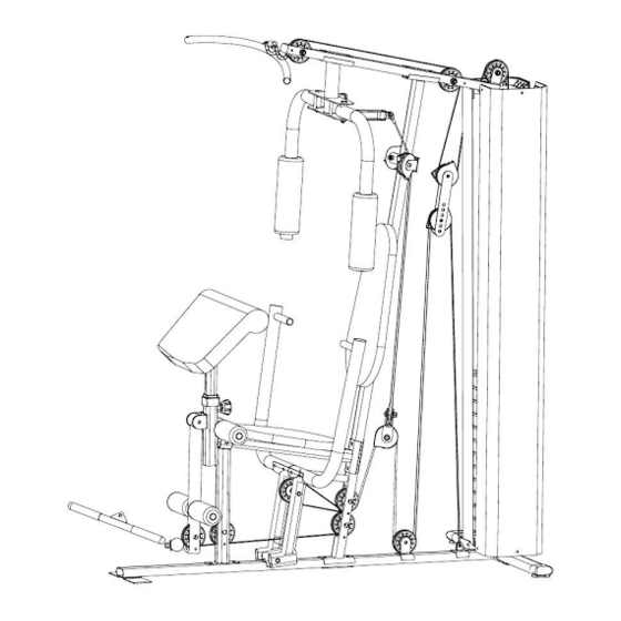
Everlast 58Kgs Home Gym
Assembly & User Instructions-
Please Keep for future reference
612/7712
Important –
Please read these instructions fully before assembly or use
These instructions contain important information which will help you get the best from your
equipment and ensure safe and correct assembly, use and maintenance.
If you need help or have damaged or missing parts, call the Customer Helpline: 0345 600 1714
or visit www.argos-support.co.uk
Issue 1 -25/05/16
Advertisement
Table of Contents

Related Manuals for Everlast 612/7712


Summary of Contents for Everlast 612/7712
- Page 1 Everlast 58Kgs Home Gym Assembly & User Instructions- Please Keep for future reference 612/7712 Important – Please read these instructions fully before assembly or use These instructions contain important information which will help you get the best from your equipment and ensure safe and correct assembly, use and maintenance.
-
Page 2: Table Of Contents
Contents Safety Information Components – Parts Components – Fixings Assembly Instructions 7-25 Workout Area Exercise Information 27-36 Before starting Muscle Chart Warming up and Cooling down Using the home gym 31-35 Home gym adjustment Care and Maintenance Parts List... -
Page 3: Safety Information
Safety information Important – Please read fully before assembly or use This exercise equipment is built for optimum safety. However, certain precautions apply whenever you operate a piece of exercise equipment. Be sure to read the entire manual before you assemble , operate or use this equipment. -
Page 4: Components - Parts
If you have damaged or missing parts, please Components - Parts call the Customer Helpline: 0345 600 1714. Please check you have all parts listed below Note: Some of the smaller components may be pre-fitted to larger components. Please check carefully before contacting Argos regarding any missing components. - Page 5 If you have damaged or missing parts, please Components - Parts call the Customer Helpline: 0345 600 1714 Please check you have all parts listed below U Bracket x 1 Pull Bar x 1 Front Support Frame x 1 Selector Rod x 1 Angled Double Swivel Pulley Pulley Bracket...
- Page 6 If you have damaged or missing parts, please Components - Parts call the Customer Helpline: 0345 600 1714 Please check you have all parts listed below Backrest Seat Pad x 1 Arm Curl Pad x 1 Pad x 1 Bracket x 4 15 Joint Clip Hook x 2 Chain x 1...
-
Page 7: Components - Fixings
Components - Fixings Please check you have all parts listed below Note: The quantities below are the correct amount to complete the assembly. In some cases more hardware may be supplied than are required. Some of the fixings are pre-fitted to the larger components. Please check carefully before contacting Argos regarding any missing fixings. -
Page 8: Assembly Instructions
Assembly Instructions Step 1 a. Insert the Guide Rods (14) into the holes on the Rear stabilizer (2) using 2 x M10X25mm Allen Bolts (44) and 2 x Ø10 Washers (56). b. Attach the Rear Stabilizer (2) to the Main Base Frame (1) using 1 x U Bracket (15), 2 x M10 Aircraft Nuts (57), 4 x Ø10 Washers (56) and 2 x M10X90mm Allen Bolts (51). - Page 9 Assembly Instructions Step 2 Secure the 2 x Lower Fixed Frames (80) to the Rear Stabilizer (2) using 2 x M10 x 25mm Allen Bolts (44) and 2 x Ø10 Washers (56) , then put 2 x Rubber Bumpers (82) through the 2 x Guide Rods (14).
- Page 10 Assembly Instructions Step 3 Attach the Vertical Frame (3) to the Main Base Frame (1) using 1 x Bracket (40), 2 x M10X50mm Carriage Bolts (42), 2 x Ø10 Washers (56) and 2 x M10 Aircraft Nuts (57).
- Page 11 Assembly Instructions Step 4 a. Carefully slide 12 x Weight plates (73) down the Guide Rods (14). b. Insert the Selector Rod (16) down through the center holes of the weight stack. Slide the Upper Weight plate (72) down the Guide Rods (14). c.
- Page 12 Assembly Instructions Step 5 a. Slide the Upper Fixed Frame (79) down the Guide Rod (14). b. Attach the Upper Frame (4) and 1 x Bracket (40) to the Vertical Frame (3) using 2 x M10 x 50mm Carriage Bolts (42), 2 x Ø10 Washers (56) and 2 x M10 Aircraft Nuts (57). c.
- Page 13 Assembly Instructions Step 6 Attach the Butterfly Frame (5) and 1 x Bracket (40) to the Upper Frame (4) using 2 x M10 x 50mm Carriage Bolts (42), 2 x Ø10 Washers (56) and 2 x M10 Aircraft Nuts (57). Notes: (65) is pre-fitted.
- Page 14 Assembly Instructions Step 7 a. Attach the Front Press Base (9) to the Main Base Frame (1) using 1 x Axle (24), 2 x Ø10 Washers (56) and 2 x M10 Aircraft Nuts (57). b. Attach 2 x Front Press Handles (10) to the Front Press Base (9) using 4 x M10 X 68mm Allen Bolts (48), 8 x Ø10 Washers (56) and 4 x M10 Aircraft Nuts (57).
- Page 15 Assembly Instructions Step 8 Attach the Front Support Frame (17) to the Main Base Frame (1) using 2 x M10X25mm Allen Bolts (44) and 2 x Ø10 Washers (56). Notes: please do not fasten the bolts at this step.
- Page 16 Assembly Instructions Step 9 a. Attach the Seat Support (6) to the Vertical Frame (3) using 1 x Bracket (40), 2 x M10X50mm Carriage Bolts (42), 2 x Ø10 Washers (56) and 2 x M10 Aircraft Nuts (57). b. Attach the Seat Support (6) to the Front Support Frame (17) using 1 x M10X68mm Allen Bolt (48), 2 x Ø10 Washers (56) and 1 x M10 Aircraft Nuts (57).
- Page 17 Assembly Instructions Step 10 a. Fix the Leg Developer (11) to the Seat Support (6) using 2 x M10X25mm Allen Bolt (44), 2 x Ø10 Washer (56), Notes: (66), (78), (59), (26), (43) are pre-fitted.
- Page 18 Assembly Instructions Step 11 Insert the Arm Curl Support (18) into the hole of the Seat Support (6) and secure with 1 x M18 Lock Knob (77).
- Page 19 Assembly Instructions Step 12 a. Attach the Left & Right Fly Arm (7, 8) to the Butterfly Frame (5) using 2 x Connecting Rods (23), 2 x Ø10 Washers (56) and 2 x M10 Aircraft Nuts (57). b. Slide 2 x 22mm Butterfly Foam Pads (35) onto the Left & Right Fly Arm (7, 8). Notes: (66) is pre-fitted.
- Page 20 Assembly Instructions Step 13 a. Attach the Seat Pad (37) to the Seat Support (6) using 4 x M8X18mm Allen Bolt (53) and 4 x Ø8 Washers (55). b. Attach the Backrest Pad (38) to the Vertical Frame (3) using 2 x M8X40mm Allen Bolt (54) and 2 x Ø8 Washers (55).
- Page 21 Assembly Instructions Step 14 a. Insert 2 x Foam Roll Tubes (25) half way into the Seat Support (6) and Leg Developer (11) respectively. b. Push 4 x 22mm Foam Pads (36) onto each side of the Foam Roll tubes (25). c.
- Page 22 Assembly Instructions Step 15 a. Attach the Swivel Pulley Bracket (21) to the Vertical Frame (3) using 1 x M10X68mm Allen Bolt (48), 2 x Ø10 Washers (56) and 1 x M10 Aircraft Nut (57). b. Attach 2 x Cable Pin Brackets (22) to the Left and Right Fly Arm (7, 8) respectively, and secure using 2 x M10X50mm Allen Bolts (47), 4 x Ø10 Washers (56) and 2 x M10 Aircraft Nut (57).
- Page 23 Assembly Instructions Step 16 a. Thread the Upper Cable (27) through the Upper Frame (4), and fix 1 x Ø78 Pulley (70) to the Upper Frame (4) using 1 x M10X85mm Allen Bolt (50), 2 x Pulley Bushes (31) and 1 x M10 Aircraft Nut (57). b.
- Page 24 Assembly Instructions Step 17 a. Fix one end of the Butterfly Cable (29) to the Right Fly Arm (7) using 1 x Cable Pin Bracket (22), 1 x M10X25mm Allen Bolt (44), 2 x Ø10mm Washers (56) and 1 x M10 Aircraft Nut (57). b.
- Page 25 Assembly Instructions Step 18 a. Thread the Lower Cable (28) through the Leg Developer (11), and fix 1 x Ø78 Pulley (70) using 1 x M10 x 60mm Allen Bolt (49), 2 x Pulley Bushings (32) and 1 x M10 Aircraft Nut (57). b.
- Page 26 Assembly Instructions Step 19 a. Connect the Lat Bar (12) to the hook on the Upper Frame (4) using 1 x 15 Joint Chain (62) and 2 x #6 Clip Hooks (63). b. Fix 2 x Weight Stack Cover (41) using 12 x ST6X20 Phillips Screws (58). Notes: (69) are pre-fitted.
-
Page 27: Workout Area
Workout Area The free area must be at least 0.6m greater than the training area. This is a space where you can safely dismount, without obstruction, in case of an emergency. Where two pieces of equipment are positioned adjacent to each other the free area may be shared. Only one person should be within the training area when the equipment is in use. -
Page 28: Exercise Information
Exercise Information Before starting Tailor your exercise program according to your physical condition. If you have been inactive for several years, or are overweight, you must start slowly and increase your time on the equipment; a few minutes per workout increase is advisable. Initially, you may be able to exercise only for a few minutes in your target zone, however, your aerobic fitness will improve over the next six to eight weeks. -
Page 29: Muscle Chart
Exercise Information Muscle Chart Aerobic Exercise Aerobic exercise improves the fitness of your lungs and heart - your body’s most important muscle. Aerobic exercise is promoted by any activity that uses your large muscles (arms, legs, or buttock, for example). Weight Training Along with aerobic exercising which helps get rid of and keep off the excess fat that our bodies can store, weight training is an essential part of an exercise routine. -
Page 30: Warming Up And Cooling Down
Exercise Information Warming up and Cooling down Each workout should include the following three parts: 1. A warm-up, consisting of 5 to 10 minutes of stretching and light exercise. A proper warm-up increases your body temperature, heart rate, and circulation in preparation for exercise. 2. - Page 31 Exercise Information Calf/Achilles stretch With one leg in front of the other, reach forward and place your hands against a wall. Keep your back leg straight and your back foot flat on the floor. Bend your front leg, lean forward and move your hips toward the wall.
-
Page 32: Using The Home Gym
Exercise Information Using the home gym Important: When working out, do the following for each exercise: exhale while exerting/lifting and inhale while returning to starting position in a slow and controlled manner. Read all caution and warning stickers before using this equipment. Before using, inspect the equipment for loose, frayed, or worn parts, if in doubt. - Page 33 Exercise Information Standing Biceps Curl Developing the Biceps Select the desired weight. Attach ‘Pull bar’ and chain to Lower pulley using Clip hooks. Stand over the lower pulley positioning feet on front foot plate. Grasp ‘Pull bar’ with palms facing up. With elbows at your side and arms fully extended, curl Pull bar upwards by pivoting from the elbows.
- Page 34 Exercise Information Seated Leg Extension Developing the Quadriceps Select the desired weight. Position back of your knees on top of Foam rolls. Position top of your ankles against lower Foam rolls. Extend your legs forward, pivoting from the knees, to full extension.
- Page 35 Exercise Information Front Deltoid Raise Developing the Front Deltoids Select the desired weight. Attach ‘Pull bar’ and chain to Lower pulley using Clip hooks. Stand over lower pulley, positioning feet on front foot plate. Grasp ‘Pull bar’ with palms facing down and begin exercising with arms extended below waist.
- Page 36 Exercise Information Upright Row Developing the Deltoids/Trapezius Select the desired weight. Attach ‘Pull bar’ and chain to Upper pulley using Clip hooks. Stand over the lower pulley, positioning feet on the front foot plate. Grasp ‘Pull bar’ with both hands and begin exercise with arms extended below the waist.
-
Page 37: Home Gym Adjustment
Exercise Information Home gym adjustment When using: Select the desired training weight by inserting the Weight select pin (30) into the deep grooves under the Weight plates and into the Select rod. When not in use: Insert the Weight selection pin (30) into the Rear U-shaped bracket (15) on the Rear stabilizer (2). -
Page 38: Care And Maintenance
Care and Maintenance and/or keep the equipment out with assembly, operation or The safety level of the of use until repair. use of your exercise product equipment can only be Pay special attention to or if you think that you may maintained if it is examined components most susceptible have parts missing, contact... -
Page 39: Parts List
Parts List Part # Description QTY Part # Description M6X16mm Allen Bolt Front Stabilier Frame Rear Stabilizer M10X25mm Allen Bolt Vertical Frame M10X40mm Allen Bolt Upper Frame M10X45mm Allen Bolt Butterfly Frame M10X50mm Allen Bolt Seat Support M10X68mm Allen Bolt Right Fly Arm M10X60mm Allen Bolt Left Fly Arm... - Page 40 Guarantee Product Guarantee This product is guaranteed against manufacturing defects from a period of Year This product is guaranteed for twelve months from the date of original purchase. Any defect that arises due to faulty materials or workmanship will either be replaced, refunded or repaired free of charge where possible during this period by the dealer from whom you purchased the unit.
Need help?
Do you have a question about the 612/7712 and is the answer not in the manual?
Questions and answers