
Related Manuals for Jackson Systems COMFORT SYSTEM Z-2000-T


Summary of Contents for Jackson Systems COMFORT SYSTEM Z-2000-T
- Page 1 Z-2000-T INSTALLATION / OPERATION MANUAL VERSION 1.3 www.jacksonsystems.com 1.888.652.9663...
-
Page 3: Terminal Designations
Due to ongoing product improvement, Jackson Systems reserves the right to change the specifications of the Z-2000-T without notice. C R PO PC DS DS Y W A B All right reserved. -
Page 4: Thermostat Location
THERMOSTAT LOCATION Do not over-tighten the terminal screws. Check to see that all wires are landed The Z-2000-T should be installed in a correctly and dressed properly to location that represents the ambient prevent any shorts. space temperature. Do not install the thermostat in an area where drafts are SWITCH FUNCTIONS present, near the floor, behind doors or... -
Page 5: System Wiring Diagrams
SYSTEM WIRING DIAGRAMS Zone One™ Modulating Damper or Diffuser System DAMPER OR DIFFUSER ACTUATOR Z-2000-T ACTUATOR BOARD AUTO CHANGEOVER SPACE THERMOSTAT RED LED INDICATES A CALL FOR HEATING DAMPER OPEN (24VAC) DAMPER CLOSED (24VAC) HEAT CALL FOR HEAT (24VAC) 24 VAC POWER (HOT) OPEN PURPLE... -
Page 6: Key Functions
ATTACHING THERMOSTAT TO KEY FUNCTIONS THE SUBBASE When attaching the thermostat to the A = ON/OFF KEY - When the subbase, first place the hinged access cover Z-2000-T is not locked, this key allows on by fitting the plastic molded pins into the the thermostat to be turned ON or OFF. -
Page 7: Entering The Setup Menu
SETTING THE MAXIMUM DAMPER ENTERING THE SETUP MENU POSITION Press twice and hold the SETUP key Press the SETUP key again and the until the word DAMPER appears on the LCD will display the maximum damper LCD. (Figure 2) position for heating and cooling. The factory default is 100% which means the damper can drive fully open with a call for heating or cooling. - Page 8 SETTING THE COOLING LIMIT SETTING A ZONE NUMBER Press the SETUP key again and the Press the SETUP key again and the LCD will display the cooling limit. The LCD will display the word ZONE. The factory default is 68° F. Press the UP factory default is 00.
-
Page 9: Setting The Modbus Address
TEMPERATURE CALIBRATION SETTING THE MODBUS ADDRESS Press the SETUP key again and the OFFSET Press the SETUP key again and the LCD will display the Modbus LCD will display the temperature communications address. The factory calibration offset. The factory default default is 01. -
Page 10: Setup Menu
CHECKING THERMOSTAT SAVING SETTINGS AND EXITING THE STATUS POINTS SETUP MENU Press the ENTER key and the Z-2000-T After the thermostat is locked and operational, its status functions can be will save the setup menu settings and exit checked by pressing the STATUS key the program. -
Page 11: Advanced Functions
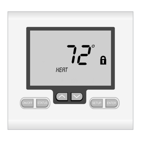
CALL FOR COOLING CHANGING THE SETPOINT When the thermostat calls for cooling, When the UP and DOWN keys are the word COOL will be displayed on the pressed, the thermostat will display the LCD. (Figure 16) word SET. The setpoint then can be changed within the setpoint limits. - Page 12 CANCELLING THE DAMPER OVERRIDE TO OPEN OVERRIDE Press the UP and DOWN keys until the In order for the Z-2000-T to control normal word OPEN appears on the LCD and damper operation, the override must be then press the ENTER key. The damper cancelled.
Need help?
Do you have a question about the COMFORT SYSTEM Z-2000-T and is the answer not in the manual?
Questions and answers