Jackson Systems WCT-32 Installation Manual
Hide thumbs
Also See for WCT-32:
- User manual (4 pages) ,
- Installation manual (9 pages) ,
- User manual (4 pages)
Table of Contents
Advertisement
Quick Links
Specifications
Compatible Equipment
Output Terminals
Fan Operation
LED Indicator
Communications
Range
Control Module Power
Control Module Housing
Control Module Dimensions
Thermostat Dimensions
Application
SY ST EM
FA N
Features
Single stage, multi-stage and heat pumps (3 heat / 2 cool)
W1/B, O, W2/E, Y1, Y2, G
Gas or electric
Multi-color indicates heating, cooling and fan calls
Wireless, 915MHz, proprietary protocol
Up to 100 feet
24VAC, 2.4VA
Molded plastic
5.09 x 2.65 x 1.10 inches (WHD)
5.00 x 4.50 x 1.00 inches (WHD)
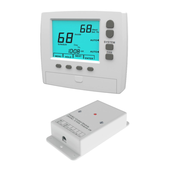
Installation Manual
Model WCT-32
The SC-WCT32 is a 7-day programmable,
battery powered thermostat that
communicates via an RF wireless data link to
a relay control module located near the HVAC
equipment.
The SC-WCT32 can control single stage,
multi-stage and heat pumps with up to 3
stages of heating and 2 stages of cooling.
Manual or programmable selection with up
to four schedules per day.
Exclusive Memory Backup insures reliable
performance in the event of a
communications interruption.
Wireless 915MHz proprietary protocol with
up to 100' transmission range.
Easy access, front-loading battery
compartment. 2 AA batteries included.
Advertisement
Table of Contents

Subscribe to Our Youtube Channel
Related Manuals for Jackson Systems WCT-32


Summary of Contents for Jackson Systems WCT-32
- Page 1 Installation Manual Model WCT-32 Application The SC-WCT32 is a 7-day programmable, battery powered thermostat that communicates via an RF wireless data link to a relay control module located near the HVAC equipment. SY ST EM The SC-WCT32 can control single stage,...
-
Page 2: Installation
2.65” HVAC Module .187” dia. 2 plcs Installation The HVAC module should be installed close to 5.09” the equipment being controlled. Do not install it 4.57” within a metal enclosure that might interfere with wireless communications. Only standard 18 gauge thermostat wire is required to wire the module to the equipment. -
Page 3: Installing The Sub-Base
Thermostat Installing the Sub-Base The thermostat should be installed approximately Location 5 feet above the floor. The thermostat should be located in an area that Level the sub-base for appearance and use the represents the ambient space temperature and wall anchors and screws provided. within 100 feet of the HVAC Control Module. -
Page 4: Thermostat Installer Options
Installer Options Chart Option Description Thermostat Installer Options Zone number Range 01 to 08 Default The installer options can be accessed by Home number Range 01 to 32 pressing and holding the ENTER key for seven Default seconds. The LCD displays Option 01 for setting Program HVAC module with Zone the Zone number. -
Page 5: Selecting Equipment Type
The LCD display for Option 03 is shown below. Use the Up and Down keys to set the Home Press the ENTER key to send the new address to number for the thermostat. The Home number the HVAC module after pressing the module can be set from 01 to 32. - Page 6 Set To Heating Setpoint Limit The maximum heating setpoint the user can set is 60 to 85F. Press the NEXT key to select Option 08 and press the Up or Down key to set maximum Option allowable heating setpoint. CANCEL NEXT ENTER Set To...
-
Page 7: First Stage Differential
Press the NEXT key to select Option 12 and the Press the NEXT key to select Option 11 and Up or Down key to set the second stage press the Up or Down key to set the setpoint differential. temperature differential. If the first stage temperature differential is greater than third stage temperature differential, first stage differential will automatically be incremented. -
Page 8: Automatic Backup
comparing the temperature readings. Press and hold the ENTER key for seven seconds until the LCD displays Option 01. Press the NEXT key Set To until Option 17 appears. Use the Up and Down keys to set the proper temperature to be displayed and then press ENTER.
Need help?
Do you have a question about the WCT-32 and is the answer not in the manual?
Questions and answers