Advertisement
TABLE OF CONTENTS
Kit Contents .................................................................... 1
Sapphire & Sapphire-D................................................... 2-3
Topaz (Serial No. 874593 And Below) .......................... 2-3
Topaz (Serial No. 874594 and above) & Castile Gas ... 4
Garnet & Tiara Petite ...................................................... 5-6
DV400 & DV450 ............................................................. 7-8
Dv750............................................................................. 9-10
Number
1
Blower Mounted in Housing
2
Speed Control Knob
3
Pal Nut
4
Ceramic Snap Disc
5
Speed Control (Rheostat)
6
Wire Harness (attached to
blower)
7
12 Screws
8
12 inch Tape Gasket
9
1 Zip Tie
10
Snap Disc Bracket
11
Bracket #1
DIRECT VENT GAS APPLIANCES
BLOWER KIT INSTALLATION
Part: BK-GAS
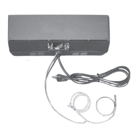
Kit Contents for All Models
Description
7016-139 Rev. D
NOTE: Open and inspect contents of BK-GAS. The
contents of the kit are listed below. If any of the parts
are missing or damaged, please contact your dealer for
replacements.
NOTE: Not all components are used for all installations.
10
Blower Notes for All Models
NOTE: The blower will not run until the appliance has heated
up enough to activate the snap disc. This can take up to 15
minutes depending on the temperature of the room. Likewise,
the blower will not turn off until the appliance has cooled off
enough to turn off the snap disc.
• Turning the control knob to the left (counterclockwise) until
you hear an audible click will turn the blower "OFF".
• Turning the control knob to the right (clockwise) until you
hear an audible click will turn the blower "ON".
• Turning the control knob further to the right will reduce the
speed of the blower.
7/11 Page 1 of 8
11
Advertisement
Table of Contents

Related Manuals for Hearth & Home BK-GAS


Summary of Contents for Hearth & Home BK-GAS
- Page 1 BLOWER KIT INSTALLATION Part: BK-GAS TABLE OF CONTENTS NOTE: Open and inspect contents of BK-GAS. The contents of the kit are listed below. If any of the parts Kit Contents ..............1 are missing or damaged, please contact your dealer for Sapphire &...
- Page 2 SAPPHIRE (All Serial Numbers) TOPAZ (Serial Numbers 874593 & Below) From The Kit You Will Need: Blower mounted in housing with wiring harness; Bracket #1; snap disc bracket; speed control (rheostat); speed control knob; snap disc; screws; and 1 zip-tie. Tools Required: #2 Phillips head screwdriver;...
- Page 3 SAPPHIRE TOPAZ (Serial No. 874594 & Above) TOPAZ #874593 & below (Cont’d) CASTILE GAS, SAPPHIRE-D Installing Speed Control From The Kit You Will Need: Blower mounted in housing Sapphire: Remove the speed control housing from the with wiring harness; speed control (rheostat); speed control knob;...
- Page 4 TOPAZ #874594 & above GARNET & TIARA PETITE CASTILE GAS, SAPPHIRE-D (Cont’d) From The Kit You Will Need: Blower mounted in housing 4. Connect the electrical connector to the snap disc. with wiring harness; speed control (rheostat); speed Figure 11. control knob;...
- Page 5 1 zip-tie. place. Pull the cover forward, down and out. From BK-GAS-ADPT Kit You Will Need: Bracket #2 and Attach the snap disc bracket to the stud located the speed control housing under the left side of the appliance using the 10-32 nut.
- Page 6 7. Route the white wires through the snap disc bracket and attach the wire terminals to the snap disc Pull fl ush in DV400 & DV450 (Cont’d) the bracket. . Figure 24. 8. Remove the screw as shown in Figure 25 (DV400) or Figure 26 (DV450) and save for use in Step 9.
- Page 7 Figure 30. 5. Attach the blower housing to the rear of the appliance using four screws supplied with the BK-GAS kit. (Two on each side as shown in Figure 31. NOTE: Make sure the snap disc contacts the bottom of the fi...
- Page 8 DV750 (Cont’d) 6. Install the speed control (rheostat) in the housing. Tighten the pal nut on the speed control until snug using an 11/16” wrench. Figure 32. 7. Install the speed control knob. 8. Attach the speed control housing to the rear cover shield with two screws.
Need help?
Do you have a question about the BK-GAS and is the answer not in the manual?
Questions and answers