Advertisement
Quick Links
Advertisement

Subscribe to Our Youtube Channel
Related Manuals for Runxin 53520


Summary of Contents for Runxin 53520
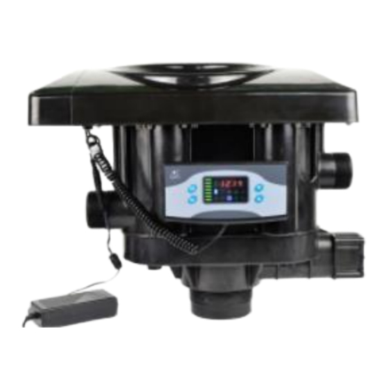
- Page 1 Runxin 53520 Filter Valve Instruction Manual Page | 1...
-
Page 2: Table Of Contents
Table of Contents Installation Summary Page 3 General Specifications Page 4 Installation Page 5 Service cycles Page 6 Parameter Settings Page 7 Valve Breakdown Page 8 Circuit Board Functions Page 9 Valve Settings Page 10-11 Flow Rate Curve Page 12 Trouble Shooting Page 13-14 Page | 2... -
Page 3: Installation Summary
Installation Summary Installation Location: Installation Date: Installed by: Phone: Application Type: Water Source: Water Test Results Hardness: Iron: Other: Misc: Tank Size: Diameter Height: Resin or Media Type: Resin or Media Volume: Brine tank Size: Capacity: Service Flow Rate: Min: Max: Backwash: Inlet Pressure:... -
Page 4: General Specifications
General Specifications Operating Minimum/Maximum operating pressures: 20psi (138kPa) – 87psi (600kPa) Minimum/Maximum Operating Temperature: 5°C -50°C Power Supply: 240V/50Hz DC24V 1.5A Connections Inlet: 2” Male BSP Outlet: 2” Male BSP Waste: 2” Male BSP Riser Pipe: 2” D-GB (63mm OD) Tank Thread: 4”-8UN Page | 4... -
Page 5: Installation
Installation Before Installation, read instructions thoroughly. The installation of the system should be completed by a professional. 36x72” GS1000 High Absorption micro pollutants, Carbon Media Loading: 160kg 3-6mm #5 Underbed Gravel (Load in tank first) 80kg 8/16 #6 Underbed Gravel (Load in tank second) 210kg GS1000 (8x30) Carbon (Load in tank last) 342LPM Backwash Flow control supplied with valve Use filling funnel provided:... - Page 6 Riser pipe should be cut off flush with the top of the cylinder and deburred. Centre the riser in the cylinder and plug to not allow any media to enter riser when filling the cylinder, fill the media as per suppliers’ recommendations. Remove plug and fill system slowly with water Once cylinder is 90% full of water install the valve, making sure not to cross thread the valve.
- Page 7 System Status Service Status: Unfiltered water is directed through the media bed and up through the distributor and riser pipe. Backwash Status: The flow of water is redirected down the riser and up through the media bed. lifting the media and removing the sediment down the waste line. Fast Rinse Status: The Flow of water is directed through the media bed and up through the distributor and riser pipe and sent to drain.
- Page 8 Display Icons Runxin Controller Parameter Specifications Page | 8...
-
Page 9: Valve Breakdown
Valve Breakdown Page | 9... - Page 10 Sends signal in between cycles Interlock Function The circuit board has an interlock function to send a signal between Runxin valves in a parallel set up. When one of the units has started a backwash, the signal will be sent to the other valve and lock it out from performing a backwash until the first valve has completed its cycles.
- Page 11 Initial Power Up The valve may need to return to the service position. The ceramic disc will return to service position and -00- will be displayed when in motion. This should be completed within 1 minute (if this takes longer than 2minutes please contact Dealer) To initiate a Manual Regeneration –...
- Page 12 How to change Regeneration Days Override – From the F-00 setting press the down arrow – The hourglass symbol and enquiry/setting symbol will be illuminated, – Press the Menu Button – The Digits will then flash change the number to desired number of days by pressing the up or Down button &...
-
Page 13: Flow Rate Curve
Flow rate Curve Page | 13... -
Page 14: Troubleshooting
Troubleshooting Problem Possible Cause Solution Filter Fails to a. Power to controller has a. Check power Backwash been interrupted connection is ok b. Backwash cycle times set b. Reset the backwash incorrectly cycle times c. Controller Damaged c. Check or replace controller Filter passing a. - Page 15 c. Transformer damaged d. Replace transformer d. Incorrect voltage with correct size No display on a. Wiring between the a. Check a replace cable controller display board and control b. Replace control board board failure c. Replace display board d. Check or replace b.
- Page 16 Page | 16...
Need help?
Do you have a question about the 53520 and is the answer not in the manual?
Questions and answers