Advertisement
Quick Links
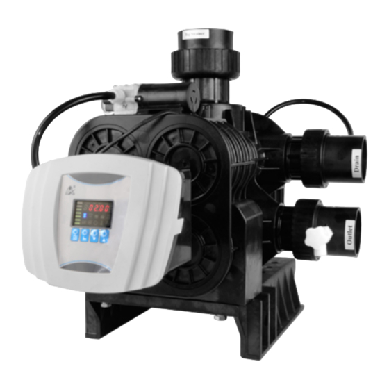
Multi-functional Flow Control Valve for
Water Treatment Systems
Please read this manual in details before using the valve and
51240B (F112BS)
53540B (F112B1)
53640B (F112B3)
61240B (F112AS)
63540B (F112A1)
63640B (F112A3)
User Manual
keep it properly in order to consult in the future.
China patent No.:
ZL02220153.X,
ZL200720045551.5
0WRX.466.612
Advertisement

Related Manuals for Runxin 51240B (F112BS)


Summary of Contents for Runxin 51240B (F112BS)
- Page 1 China patent No.: ZL02220153.X, ZL200720045551.5 Multi-functional Flow Control Valve for Water Treatment Systems 51240B (F112BS) 53540B (F112B1) 53640B (F112B3) 61240B (F112AS) 63540B (F112A1) 63640B (F112A3) User Manual Please read this manual in details before using the valve and keep it properly in order to consult in the future. 0WRX.466.612...
- Page 2 MODEL 51240B/53540B/53640B/61240B/63540B/63640B Before the valve put into use, please fill in the below content so as to help us to refer in the future. The Program Type Setting (Operation by professional) When all symbols light on, press and hold buttons for 5 seconds to enter the menu of valve model selection.
- Page 3 MODEL 51240B/53540B/53640B/61240B/63540B/63640B (63540B/63640B) Slow Rinse Time min.:sec. 45:00 (63540B/63640B) Brine Refill Time min.:sec. 05:00 (63540B/63640B) Fast Rinse Time min.:sec. 10:00 Interval Regeneration Days (63640B/53640B) Output Mode b-01(02) b-01 K Value (Only for Meter Type) 4.194 If there is no special requirement when product purchase, we choose 4# drain line flow control (with six pieces of φ8 holes) and 4# injector (7804) for the standard configuration for 63540B, 63640B and 61240B.
- Page 4 MODEL 53540B-F112B1/53640B-F112B3/63540B-F112A1/63640B-F112A3 Catalogue Notice ......................1.Product Overview ..................1.1.Main Application & Applicability .............. 1.2.Product Characteristics ................1.3.Service Condition ................... 1.4.Product Structure and Technical Parameters ........1.5. Installation ..................... 2. Basic Setting & Usage ................2.1.The Function of PC Board ..............2.2.Basic Setting &...
- Page 5 MODEL 53540B-F112B1/53640B-F112B3/63540B-F112A1/63640B-F112A3 Notice To ensure normal operation of the valve, please consult with professional installation or repairing personnel before use it. If there are any of pipeline engineering and electric works, there must be finished by professional at the time of installation. ...
-
Page 6: Product Overview
MODEL 51240B/53540B/53640B/61240B/63540B/63640B be installed before the water inlet. While, if the water pressure under 0.2MPa, a diaphragm pump must be installed before the water inlet. It is suggested to install PPR pipe, corrugated pipe or UPVC pipe, instead of TTLSG pipe. ... - Page 7 MODEL 51240B/53540B/53640B/61240B/63540B/63640B Brine refilling is controlled by electric ball valve, refilled when in service, shorten the regeneration time. Brine refilling and service are operating in the meanwhile, for fixed bed, the water for brine refilling is hard water. Fixed bed regeneration softener could be converted to filter system.
- Page 8 MODEL 51240B/53540B/53640B/61240B/63540B/63640B Interlock function It has a function of interlock to realize only one valve in regeneration but the other valves are in service while several valves parallel in system. In multi-steps treatment systems such as RO pre-treatment, when several valves are in series, there is only one valve in regeneration or washing to ensure pass water all the times while different valves in regeneration or washing.(Application refers to Figure 3-9)
- Page 9 MODEL 51240B/53540B/53640B/61240B/63540B/63640B installed on the inlet to increase the system water feeding pressure, this cut-off will cause pressure on inlet rising too fast to damage the valve. Pressure relief output can be used to avoid this problem. (Application refers to Figure3-10) ...
- Page 10 MODEL 51240B/53540B/53640B/61240B/63540B/63640B Down-flow regeneration (61240B/63540B/63640B)<5FTU Water turbidity Filter (51240B/53540B/53640<20FTU <6.5mmol/L; First Grade Na Water hardness Inlet water <10mmol/L Second Grade Na quality <0.1mg/L Free chlorine <0.3mg/L Iron <2mg/L(O ) CODMn In the above table, First Grade Na represents First Grade Na Exchanger.
- Page 11 MODEL 51240B/53540B/53640B/61240B/63540B/63640B 63540B (F112A1): 51240B (F112BS): 61240B (F112AS):...
- Page 12 MODEL 51240B/53540B/53640B/61240B/63540B/63640B B. Technical parameter The suitable output of transformer for control valve: DC24V, 4.0A Connect Size Flow Rate Regener Regenerati Top and Model ation Remark Inlet/O Brine Line Drain Bottom @0.2MPa Mode utlet Connector Connector Strainer 51240B Manual Please 53540B By days DN65 DN65...
- Page 13 MODEL 51240B/53540B/53640B/61240B/63540B/63640B Before installation, read all those instructions completely. Then obtain all materials and tools needed for installation. The installation of product, pipes and circuits, should be accomplished by professional to ensure the product can operate normally. Perform installation according to the relative pipeline regulations and the specification of Water Inlet, Water Outlet, Drain, and Brine Line Connector.
- Page 14 MODEL 51240B/53540B/53640B/61240B/63540B/63640B Figure 1-1 D. Pipeline installation, take 63640B (F112A3) as example ① Install control valve a. As the Figure 1-2 shows, insert the riser pipe to the bottom strainer and put it into the bottom of the tank. b. Fill the mineral to the tank, and the height is accordance with the design code.
- Page 15 MODEL 51240B/53540B/53640B/61240B/63540B/63640B Figure 1-2 Notice: ● Avoid filling floccules substance together with resin to the mineral tank. ● Pipe installation should be straight, and shall not make control valves or the fittings by torsion.
- Page 16 MODEL 51240B/53540B/53640B/61240B/63540B/63640B ② Install flow meter and the inlet/outlet pipeline A.Install flow meter Safe notice: A. Before installation, make sure there is no pressure in pipeline and check if pressure released completely. B. Before installation, make sure the tested liquid won’t make corrosion for the probe.
- Page 17 MODEL 51240B/53540B/53640B/61240B/63540B/63640B and 5 times back of pipeline diameter. F. The measure distance of tangential path behind valve should comply with 50times front and 5 times back of pipe diameter. G. Suggest that install probe perpendicularly by pipeline, shouldn’t be installed in the bottom of pipeline.
- Page 18 MODEL 51240B/53540B/53640B/61240B/63540B/63640B E. As the staining in liquid may cause impeller rotation not smooth, it may affect the measurement accuracy of probe. Therefore, it shall inspect and clean the impeller of probe periodically. Nut A Figure1-3 b. As Figure 1-2, install a disc filter on the inlet of the filter. c.
- Page 19 MODEL 51240B/53540B/53640B/61240B/63540B/63640B step. ③ Install drain pipeline (If no special request, the injector is 7804) a. According to P28, for 63540B and 63640B, if the diameter of the tank is 1500mm, please do as step e; if the diameter of the tank is 1200mm, please do as following steps: b.
- Page 20 MODEL 51240B/53540B/53640B/61240B/63540B/63640B f. For 51240B (F112BS), 53540B (F112B1) and 53640B (F112B3) filter valve, there is no drain line flow control, please do as step e. Notice: ● Leave a certain space between the drain pipe and the sewer, avoid wastewater being absorbed to the water treatment equipment.
- Page 21 MODEL 51240B/53540B/53640B/61240B/63540B/63640B 2. Basic Setting & Usage 2.1. The Function of PC Board Time of day indicator Lights on,display the time of day. Button lock indicator Lights on, indicate the buttons are locked. At this moment, press any single button will not work (No operation in one minute, will light on and lock the buttons.) ...
- Page 22 MODEL 51240B/53540B/53640B/61240B/63540B/63640B Press after all program are set, and then the voice “Di” means all setting are success and return program display mode. Manual/Return button Press in any status, it can proceed to next step. (Example: Press in Service status, it will start regeneration cycles instantly; Press while it is in Backwash status, it will end backwash and go to Brine &Slow Rinse at once.) ...
- Page 23 MODEL 51240B/53540B/53640B/61240B/63540B/63640B Days Clock Type, regeneration by days Regener 02:00 02:00 00:00~23:59 Regeneration time;“:” lights on ation Time Water Treatmen Water treatment capacity in one 400.0 0~9999.9 circle (m Capacity Back Backwash time(Minute:Second) wash 10:00 0~99:59 Time Brine Draw 60:00 0~99:59 Brine Draw Time (Minute:Second) Time...
- Page 24 MODEL 51240B/53540B/53640B/61240B/63540B/63640B Mode b-02: Signal available only intervals of regeneration cycles and in service. (Connection refer to the Figure P5) B. Process Display (Take 63640B A-01 as example) Figure A Figure B Figure C Figure D Figure E Figure F Figure G Figure H Figure J...
- Page 25 MODEL 51240B/53540B/53640B/61240B/63540B/63640B 6. Working process: Service→ Backwash→ Brine Draw → Slow Rinse→ Fast Rinse→ Brine Refill →Service Usage After being accomplished installation, parameter setting and trail running, the valve could be put into use. In order to ensure the quality of outlet water can reach the requirement, the user should complete the below works: ①...
- Page 26 MODEL 51240B/53540B/53640B/61240B/63540B/63640B The regeneration parameters have been set when control valve left factory. Generally, it does not need to reset. If you want inquire and modify the setting, you can refer to the professional application specification. 2.3. Usage of Manual Wheel During operation of this series control valve, rotate the manual wheel to make the pointer point to the relevant position and carry out Service, Backwash, Brine &...
- Page 27 MODEL 51240B/53540B/53640B/61240B/63540B/63640B 3. Applications 3.1. Flow Chart Down-flow/Up-flow regeneration softener valve (61240B/63540B/63640B) and filter valve (51240B/53540B/53640B) flow chart: Note: ● For 51240B/53540B/53640B filter valve, only has service status, backwash status and fast rinse status. ● Brine refill is at the same time of service. When brine refill starts, the ball valve is opened, while it finished, the ball valve closes.
- Page 28 MODEL 51240B/53540B/53640B/61240B/63540B/63640B 3.2. The Function and Connection of PC Board Open the front cover of control valve, you will see the main control board and connection port as below: The main functions on main control board: Function Application Explanation If system strictly require no hard Outlet solenoid water flow from outlet or controlling valve...
- Page 29 MODEL 51240B/53540B/53640B/61240B/63540B/63640B To ensure only one Use in RO Pre-treatment, water Interlock control valve supply together but regeneration in connector regeneration or turn. Second grade ion exchange washing in system. equipment, etc. It is used for on-line inspection Remote Receipt signal to system, PC connection, and realize handling make the control...
- Page 30 MODEL 51240B/53540B/53640B/61240B/63540B/63640B ② Solenoid Valve on Inlet( Set b-02) Instruction: When inlet pressure exceeds 0.6MPa, install a solenoid valve on inlet. Control mode is b-02. Pressure relieved when valve switching, the wiring refer to Figure 3-2. As Figure 3-3 shows, it also can use the pressure relief port to work.
- Page 31 When valve in regeneration cycle, inlet always has water no matter what is water condition in water tank. As Runxin valve no water pass outlet in regeneration cycle, it ensure no water fill into brine tank.
- Page 32 MODEL 51240B/53540B/53640B/61240B/63540B/63640B 4). Control Inlet Booster Pump (Set b-01 or b-02) Instruction: If inlet water pressure is less than 0.15MPa, which makes rinse drawing difficult, a booster pump is suggested to be installed on inlet. Control mode b-01. When system in regeneration cycle, booster pump is open, the wiring refers to Figure 3-7.If the booster pump current is bigger than 5A, system need to install an contactor, the wiring refers to Figure3-8 Figure 3-7Wiring of Booster Pump on Inlet Figure 3-8 Wiring of Booster Pump on Inlet...
- Page 33 C. Pressure Relief Output Runxin valve will cut off feeding water to drain line when it switches in regeneration cycles. Thus in some water treatment system, e.g. Deep Well, one booster pump was installed on the inlet to increase the system water feeding pressure, this cut-off will cause pressure on inlet rising too fast to damage the valve.
- Page 34 MODEL 51240B/53540B/53640B/61240B/63540B/63640B D. Remote Handling Connector Used for making pure water, connected with online monitory system or PC machine: when the conductivity or other parameter reach the setting valve or PC machine give the signal, need regeneration. It can give the signal to the remote handling connector of the main control board to let it regenerate by signal time.
- Page 35 MODEL 51240B/53540B/53640B/61240B/63540B/63640B 3.3. System Configuration and Flow Rate Curve A. Product Configuration ①61240B/63540B/63640B Fixed bed control valve configuration with tank, resin volume, brine tank and injector. Resin The Minimum Salt Tank Size Flow Rate Brine Tank Injector Volume Consumption for (mm)...
- Page 36 MODEL 51240B/53540B/53640B/61240B/63540B/63640B calculated based on the 15L/(m *s) backwash intensity. B. Flow Rate Characteristic 1)Pressure-flow rate curve Softener Valve: 61240B/63540B/63640B Filter Valve: 51240B/53540B/53640B 2)Configuration for standard injector and drain line flow control Fixed bed 61240B/63540B/63640B Tank Injector Injector Draw Rate Slow Hole Qty Backwash /...
- Page 37 MODEL 51240B/53540B/53640B/61240B/63540B/63640B Dia. Model Color Rinse on Drain Fast Rinse Brine Outlet Refill 2×φ7 1200 7803 Yellow 6800 4400 8640 17.32 6×φ8 1500 7804 Blue 8340 5400 8520 27.12 Note: ①The above data in table is tested under pressure of 0.3MPa. ②Since the different in the quality of raw inlet water, capacity of resin, size of the tank and the pressure of inlet, the above data are only for reference.
- Page 38 MODEL 51240B/53540B/53640B/61240B/63540B/63640B 3.4. Parameter settlement ① Service timeT1 Water treatment capacity: (m ) ×K÷Y Hardness of Inlet Water (mmol/L) Exchange factor (mmol/L) 400~1000. Down-flow regeneration, take 400 ~ 750. If the inlet water hardness is higher, the factor is smaller. Resin volume (m (Day )...
- Page 39 MODEL 51240B/53540B/53640B/61240B/63540B/63640B (min.) T5=12×H Generally, the water for fast rinse is 3~6 times of resin volume. It is suggested to be set 10~16 minutes, but subject to the outlet water reaching the requirement. ⑥ Exchange factor Exchange factor =E/ (k×1000) )...
- Page 40 MODEL 51240B/53540B/53640B/61240B/63540B/63640B 3.5.2. K valve setting method (It is related to flow rate factor. The K valve is opposite of the flow rate factor.) When powered on, press and hold on “ ” button and “ ” button for 3 seconds, enter into K valve setting interface.
- Page 41 MODEL 51240B/53540B/53640B/61240B/63540B/63640B In program display mode, press and enter into program set mode. Press to adjust the value. 3.5.4. The Steps of Parameter Setting Items Process steps Symbol When time of day “12:12” continuously flash, it reminds to reset; 1. Press to enter into program display mode;...
- Page 42 MODEL 51240B/53540B/53640B/61240B/63540B/63640B 1. In water treatment capacity display status, it shows and 400.0. Press and enter into program set mode. Water and 400 flash; Treatm 2. Press to adjust the water treatment capacity ) ; value(m Capacit 3. Press , decimal value flashes. Press adjust the decimal value;...
- Page 43 MODEL 51240B/53540B/53640B/61240B/63540B/63640B rinse second value; 4. Press and finish adjustment, press to turn back. 1. In fast rinse time display status, it shows 5-10:00. Press and enter into program set mode. and 10 flash; Fast 2. Press to adjust the fast rinse minute time; Rinse 3.
- Page 44 MODEL 51240B/53540B/53640B/61240B/63540B/63640B ① Press and hold both to lift the button lock status( light off) ; ② Press ,and light on; ③ Press continuously until light on. Then the digital area shows: 5-12M; ④ Press and12 flash; ⑤ Press continuously until 12 changed to 15; ⑥...
- Page 45 MODEL 51240B/53540B/53640B/61240B/63540B/63640B close when control valve finished sucking brine, then slow rinse starts to work. It is about 60~65 minutes for whole process. E. Press , turning the position from Slow Rinse to Fast Rinse. lights on and start to fast rinse. After 10~15minutes, take out some outlet water for testing: If the water hardness reaches the requirement, and the chloridion in the water is almost the same, compared with the inlet water, then go to the next step.
-
Page 46: Troubleshooting
MODEL 51240B/53540B/53640B/61240B/63540B/63640B 3.7. Trouble-Shooting A. Control Valve Fault Problem Cause Correction A. Electrical service to unit A. Assure permanent electrical has been interrupted. service (Check fuse, plug, pull Softener B. Regeneration cycles set chain or switch). fails incorrect. B. Reset regeneration cycles. regenerate. - Page 47 MODEL 51240B/53540B/53640B/61240B/63540B/63640B A. Line pressure is too low. A. Increase line pressure. B. Brine line is plugged. B. Clean brine line. C. Brine line is leaking. C. Replace brine line. D. Injector is plugged. D. Clean or replace new parts. Softener E.
- Page 48 MODEL 51240B/53540B/53640B/61240B/63540B/63640B raw water. frequency of regeneration and backwash time. D. Iron removal equipment is required install before softening. Loss A. Air in water system. A. Assure that well system has mineral B. Bottom strainer broken. proper air eliminator control. through drain C.
- Page 49 MODEL 51240B/53540B/53640B/61240B/63540B/63640B after B. Hard water mixed in ring. regeneration. valve body. C. Reduce water pressure or use C. Water pressure is too pressure release function. high which result in valve D. Repair or replace the ball vale doesn’t right or the wire.
- Page 50 MODEL 51240B/53540B/53640B/61240B/63540B/63640B A. Wiring of front panel with controller fails to work. A. Check and replace the wiring. B. Control board is faulty. B. Replace control board. 1. All indictors C. Transformer damaged. C. Check and replace transformer. display D. Electrical service not D.
- Page 51 MODEL 51240B/53540B/53640B/61240B/63540B/63640B 3.8. Assembly & Parts 63640B Structure(Main body part) 63640B Valve Body Components and Part No. Item Quanti Item Description Part No. Description Part No. ntity Air Pipeline Hexagonal Bolt 5455001 5851005 Connector Seal Washer 8371011 Injector Body 8008005...
- Page 52 MODEL 51240B/53540B/53640B/61240B/63540B/63640B 8940005 Ball Valve 6922075 Washer 8952003 Seal Washer 8371019 Gasket 8156003 O-ring 8378104 Valve Body 5022088 Nozzle 8454024 O-ring 8378214 Seal Washer 8371006 Connector 8458104 Injector Cover 8315013 Seal Washer 8371021 O-ring 8378101 Filter Valve 3914001 Screw, Cross 8909019 Diaphragm Hexagonal...
- Page 53 MODEL 51240B/53540B/53640B/61240B/63540B/63640B 8940007 Air Pipeline 8465019 Note: ● For 63540B components, there is no #62 and #63 compared to 63640B. ● For 53640B components, there is no #15~#18, and change #28~#41 to 1 piece of 8323012 compared to 63640B. ● For 53540B components, there is no #62 and #63 compared to 53640B. 63640B Distribution valve...
- Page 54 MODEL 51240B/53540B/53640B/61240B/63540B/63640B 63640B Distribution Valve Components and Part No. Item Item Description Part No. Quantity Description Part No. Quantity Valve Body 5022028 Gear 5241005 Screw, Screw, Cross 8902008 8909008 Cross Locating Motor 6158007 6380041 Board 8993001 Fitting Nut 8092007 Small Gear 8241010 O-ring 8378107...
- Page 55 MODEL 51240B/53540B/53640B/61240B/63540B/63640B 61240B Valve Body Components and Part No. Item Item Description Part No. Quantity Description Part No. Quantity Air Pipeline 5455001 Nozzle 8454024 Connector Seal Washer 8371011 Seal Washer 8371006 8940005 34 Injector Cover 8315013...
- Page 56 MODEL 51240B/53540B/53640B/61240B/63540B/63640B Washer 8952003 O-ring 8378101 Gasket 8156003 Seal Washer 8371019 Electric Ball 2978052 Valve Body 5022088 valve O-ring 8378214 Seal Washer 8371021 Connector 8458104 Filter Valve 3914001 Hexagonal Connector 8458024 8940016 Animated Nut 8947008 Pipeline 8457025 Connector 8458022 Air Pipeline 8465017 Hexagonal O-ring...
- Page 57 MODEL 51240B/53540B/53640B/61240B/63540B/63640B O-ring 8378113 Corner Valve 3911004.05 O-ring 8378162 Connector 8458021 8940007 Flow Control 8468047 Hexagonal Bolt 5851005 O-ring 8378125 Injector Body 8008005 Air Pipeline 8465019 O-ring 8378104 Note: ● For 51240B components, there is no #10~#13, and change #23~#37 of 61240B to 1 piece of 8323012.
- Page 58 MODEL 51240B/53540B/53640B/61240B/63540B/63640B 61240B Distribution Valve Components and Part No. Item No Description Part No. Quantity 8860001 Label 8909014 Screw, Cross 8253033 Manual Wheel 8444018 Cover 8909008 Screw, Cross 8378078 O-ring 8092007 Fitting Nut 8378107 O-ring 8216010 Anti-friction Washer 8258009 Shaft 8370053 Seal Ring 8459025...
- Page 59 MODEL 51240B/53540B/53640B/61240B/63540B/63640B 5450003 Piston structure 5450003 Piston Components and Part No. Item Description Part No. Quantity Item Description Part No. Quantity Screw, Cross 8909008 Piston 8450006 Fitting Nut 8092047 O-ring 8378262 Seal Ring 8370102 O-ring 8378263 5450004 Piston structure 5450004 Piston Components and Part No.
- Page 60 MODEL 51240B/53540B/53640B/61240B/63540B/63640B Item Description Part No. Quantity Item Description Part No. Quantity Screw, Cross 8909008 O-ring 8378184 Fitting Nut 8092048 Piston 8450007 Seal Ring 8370102 O-ring 8378262 Bushing 8210006 O-ring 8378263 5040009 Support structure 5040009 Support components and part No. Item Quant Item...
-
Page 61: Guarantee Card
MODEL 51240B/53540B/53640B/61240B/63540B/63640B 4. Guarantee Card Dear client: This warranty card is the guarantee proof of RUNXIN brand multi-functional flow control valve. It is kept by client self. You could get the after-sales services from the supplier which is appointed by RUNXIN manufacturer. - Page 62 Time Capacity Water □ Brine & Slow Rinse Brine Refill Time Time Fast Rinse Time Problem Description WENZHOU RUNXIN MANUFACTURING MACHINE CO., LTD. ADD : Jinger Road, Shatou Group, Linjiang, Lucheng District, Wenzhou, Zhejiang, China TEL:0577-88635628 88630038 FAX:0577-88633258 http://www.run-xin.com Email:sales@run-xin.com...
Need help?
Do you have a question about the 51240B (F112BS) and is the answer not in the manual?
Questions and answers