Table of Contents
Advertisement
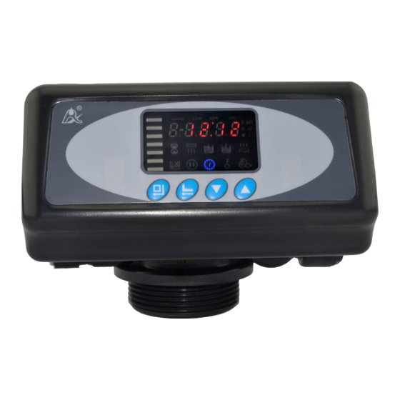
Multi-functional Flow Control Valve for
63504,63504B (Old Model No.: F63C1,F63G1)
63604,63604B (Old Model No.: F63C3,F63G3)
73504,73504B (Old Model No.: F68C1,F68G1)
73604,73604B (Old Model No.: F68C3,F68G3)
Please read this manual in details before using the valve
and keep it properly in order to consult in the future.
Water Treatment Systems
User Manual
International Patent Public No.:
WO 2006/007772
China Patent No.: ZL02220153.X,
ZL200420078956.5
US Patent No.: 7549446
India Patent No.: 232582
Russia Patent No.:2349819
South Korea Patent No.:10-0914137
Mexico Patent No.: 268581
Australia Patent No.: 2005263257
Philippine Patent No.: 1-2006-502553
Taiwan Patent No.:M287896
0WRX.466.501
Advertisement
Table of Contents


Need help?
Do you have a question about the 63504 and is the answer not in the manual?
Questions and answers