Multi-functional flow control valve for water treatment systems (51 pages)
Summary of Contents for Runxin F71B1
Page 1
China Patent No.: ZL02220153.X, ZL02257746.7 
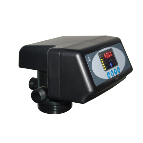
Multi-functional Flow Control Valve for Water Treatment Systems 53502(Old Model No.: F71B1) 53502B(Old Model No.:F71G1) 53504(Old Model No.:F67C1) 53504B(Old Model No.:F67G1) 53510(Old Model No.:N75A1) 53510B(Old Model No.:N75B1) User Manual Please read this manual in details before using the valve and keep it properly in order to consult in the future.
Page 2
MODEL F71B/F71G/F67C/F67G/N75A/N75B Before the valve put into use, please fill in the below content so as to help us to refer in the future. Filter System Configuration Tank Size: Dia. Height Refilled Filter Materials Granularity of Filter Materials Control Valve Model Number Pressure of Inlet Water Turbidity of Inlet Water...
Page 3
MODEL F71B/F71G/F67C/F67G/N75A/N75B Catalogue Notice ...................... 1. Product Overview ................1.1. Main Application & Applicability..........1.2. Product Characteristics ............1.3. Service Condition ..............1.4. Product Structure and Technical Parameters ....1.5. Installation................2. Basic Setting & Usage ..............2.1. The Function of PC Board ............ 2.2.
Page 4
MODEL F71B/F71G/F67C/F67G/N75A/N75B Notice To ensure normal operation of the valve, please consult with professional installation or repairing personnel before use it. If there are any of pipeline engineering and electric works, there must be finished by professional at the time of installation ...
MODEL F71B/F71G/F67C/F67G/N75A/N75B easily, it is suggested to install the strainer with M88×2 male thread. 1. Product Overview 1.1. Main Application & Applicability Used for filtering water treatment systems Be suitable for Residential filtering system Swimming pool filtering equipment (N75A1/53510, N75B1/53510B) Carbon filter or sand filter in RO pretreatment filtering system 1.2.
Page 6
MODEL F71B/F71G/F67C/F67G/N75A/N75B No operations to buttons on the controller within 1 minute, button lock indicator light on which represent buttons are locked. Before operation,press and hold the “ ”and“ ” buttons for 5 seconds to unlock. This function can avoid incorrect operation. ...
Page 7
MODEL F71B/F71G/F67C/F67G/N75A/N75B b-01 b-02 Remote handling input This connector can receive external signal, used together with PLC, and computer etc. to control the valve. (Application refer to Figure3-12) Pressure relief output The valve will cut off feeding water to drain line when it switches in rinsing cycles (Same as signal output b-02).
MODEL F71B/F71G/F67C/F67G/N75A/N75B 1.3. Service Condition Filter Valve should be used under the below conditions: Items Requirement Water pressure 0.15MPa~0.6MPa Working conditions Water temperature 5℃~50℃ Environment 5℃~50℃ temperature Working ≤95%(25℃) Relative humidity environment Electrical facility AC100~240V/50~60Hz Inlet water <20FTU Water turbidity quality Note: ...
MODEL F71B/F71G/F67C/F67G/N75A/N75B 1.5. Installation A. Installation notice Before installation, read all those instructions completely. Then obtain all materials and tools needed for installation. The installation of product, pipes and circuits should be accomplished by professional to ensure the product can operate normally.
Page 12
MODEL F71B/F71G/F67C/F67G/N75A/N75B b.Fill the mineral to the tank, and the height is accordance with the design code. c.Remove the tap covering on the central tube and check if the riser tube is on the central of tank. d.Install the top distributor to the valve and insert the riser tube into control valve and screw tight control valve.
Page 13
MODEL F71B/F71G/F67C/F67G/N75A/N75B ② Pipeline connection a. As figure 1-2 shows, install a pressure gauge in water inlet. b. Install valve A, valve B, valve C and valve D in the inlet and outlet pipeline. The valve D is sampling valve. c.
Page 14
MODEL F71B/F71G/F67C/F67G/N75A/N75B ③ Install drain pipeline Directly connect the drain with the rigid pipeline, such as UPVC, etc. Note: ●Control valve should be higher than drain outlet, and be better not far from the drain hose. ● Be sure not connect drain with sewer, and leave a certain space between them (As the figure 1-3 shows), avoid waste water be absorbing to the water treatment equipment.
Page 15
MODEL F71B/F71G/F67C/F67G/N75A/N75B 2. Basic Setting & Usage 2.1. The Function of PC Board Time of day indictor light on, display the time of day. Button lock indicator Light on, indicate the buttons are locked. At this moment, press any single button will not work (No operation in one minute, will light on and lock the buttons.)
Page 16
MODEL F71B/F71G/F67C/F67G/N75A/N75B Press light on, enter program display mode and use view all values. In program display mode, press flash, enter program set mode, press and adjust values. re set, and then the voice “Di” means all setting are success and return program display mode.
Page 17
MODEL F71B/F71G/F67C/F67G/N75A/N75B 2.2. Basic Setting & Usage A. Parameter specification Parameter Factory Function Indicator Instruction Default Range Time of Rando 00:00~ Set the time of day when use;“:” 23:59 flash. 0~ Service 1-03D. Only for Time Clock Type, by days Days 99Days Service...
Page 18
MODEL F71B/F71G/F67C/F67G/N75A/N75B B. Process Display (Time Clock Type, by days) The circular interface displays in turn Working status Service Backwash Fast Rinse Illustration: The display screen will only show “-00-” when the electrical motor is running. The time of day figure“” flash continuously, such as “12:12” flash, indicates long outage of power.
Page 19
MODEL F71B/F71G/F67C/F67G/N75A/N75B 3. Applications 3.1. Filter Flow Chart...
Page 20
MODEL F71B/F71G/F67C/F67G/N75A/N75B 3.2. The Function and Connection of PC Board Opening the front cover of control valve, you will see the main control board and connection port as figure 3-1A shows(For F71, F67)...
Page 21
MODEL F71B/F71G/F67C/F67G/N75A/N75B The main functions on main control board: Function Application Explanation If system strictly require no hard Outlet solenoid water flow from outlet valve controlling the liquid level in water tank. Signal output Increase pressure connector b-01 regeneration or rinsing. Inlet pump Use the liquid level controller to control inlet pump to ensure...
Page 22
MODEL F71B/F71G/F67C/F67G/N75A/N75B A. Signal Output Connector 1) Control Solenoid Valve (Set b-01) ① Solenoid valve on outlet controls water level in brine tank.. Instruction: If system strictly requires no unfiltered water flow from outlet in rinsing cycle (Mainly for no unfiltered water flow out when valve is switching.
Page 23
MODEL F71B/F71G/F67C/F67G/N75A/N75B Function: When inlet pressure is high, install a solenoid valve on inlet to ensure valve switching properly. When valve is exactly at position of Service, Backwash, and Fast Rinse, solenoid valve is open. When valve is switching, solenoid valve is closed, no water flow into valve to ensure valve switching properly.
Page 24
When valve in backwash cycle, inlet always has water no matter what is water condition in water tank. As Runxin valve no water pass outlet in regeneration cycle, it ensure no water fill into brine tank.
Page 25
MODEL F71B/F71G/F67C/F67G/N75A/N75B 4) Control Inlet Booster Pump( Set b-01) Instruction: If inlet water pressure is less than 0.15MPa, which makes rinse drawing difficult, a booster pump is suggested to be installed on inlet. Control mode b-01. When system in regeneration cycle, booster pump is open, the wiring refer to Figure 3-8.IF the booster pump current us bigger than 5A, system need to install an contactor, the wiring refer to Figure3-9...
Page 26
C. Pressure Relief Output Runxin valve will cut off feeding water to drain line when it switches in rinsing cycles. Thus in some water treatment system, e.g. Deep Well, one booster pump was installed on the inlet to increase the system water feeding pressure, this cut-off will cause pressure on inlet rinsing too fast to damage the valve.
Page 27
MODEL F71B/F71G/F67C/F67G/N75A/N75B D. Remote Handling Connector Online TDS meter monitors treated water other than a flow meter, or PLC controls the rinsing time. When the controller receives a contact closure from above instruments, rinsing begins. The wiring refers to Figure3-12.
Page 28
MODEL F71B/F71G/F67C/F67G/N75A/N75B 3.3. System Configuration and Flow Rate Curve A. Product Configuration Product configuration with tank, filter materials volume Carbon Filter Sand Filter Volume Filtering Backwas Filtering Backwas Tank Size of Filter Flow h Flow Flow h Flow Material Rate Rate Rate Rate...
Page 29
MODEL F71B/F71G/F67C/F67G/N75A/N75B B. Flow Rate Characteristic 1). Pressure-flow rate curve...
Page 30
MODEL F71B/F71G/F67C/F67G/N75A/N75B 3.4. Parameter Enquiry and Setting 3.4.1. Parameter Enquiry When light on, press and hold both and for 5 seconds to lift the button lock status; then press light on, enter to program display mode; press to view each value according to below process.(Press exit and turn back to service status)...
Page 31
MODEL F71B/F71G/F67C/F67G/N75A/N75B finish adjustment, press to turn back. 1. In the Rinsing Time program display mode, press and enter into program set mode, and 02 value flash;through to adjust the hour value Rinsing and “00” flash, 2. Press again, both Time through to adjust the minute...
Page 32
MODEL F71B/F71G/F67C/F67G/N75A/N75B 1. In the Fast Rinse Time display mode, it and “3-10:00”; press shows Fast Rinse enter into program set mode. Time 10:00 flash; 2. Press to adjust the value; and hear a sound “Di”, then 3. Press finish adjustment, press to turn back.
Page 33
MODEL F71B/F71G/F67C/F67G/N75A/N75B 3.5. Trial running After installing the multi-functional flow control valve on the tank with the connected pipes, as well as setting up the relevant parameter, please conduct the trail running as follows: A. Close the inlet valve B & C, and open the bypass valve A. After cleaning the foreign materials in the pipe, close the bypass valve A.
Page 34
MODEL F71B/F71G/F67C/F67G/N75A/N75B After changing the filter materials, please empty air in the materials according to the above Step B. In the process of trial running, please check the water situation in all position, ensuring there is no filter materials leakage. ...
MODEL F71B/F71G/F67C/F67G/N75A/N75B 3.6. Trouble-Shooting A. Control Valve Fault Problem Cause Correction Assure permanent A. Electrical service to electrical service (Check unit been fuse, plug, pull chain or 1.Filter fails interrupted. switch). to rinse. B. Rinse time is set B. Reset the time. incorrect.
Page 36
MODEL F71B/F71G/F67C/F67G/N75A/N75B Locating signal Check connect wiring breakdown. 5.Control locating signal wiring. B. Controller damaged. cycle B. Replace controller. Foreign material continuously. stuck the driving gear. C. Take out foreign material. A. Internal valve leak. A. Check and repair valve B.
Page 37
MODEL F71B/F71G/F67C/F67G/N75A/N75B A. Wiring of locating board with controller damaged. A. Replace wiring. Locating board Replace locating damaged. board. Mechanical driven C. Check and repair 3. E1 Flash damaged. mechanical part. Control board Replace control damaged. board. E. Wiring of motor with E.
This warranty card is the guarantee proof of RUNXIN brand multi-functional flow control valve. It is kept by client self. You could get the after-sales services from the supplier which is appointed by RUNXIN manufacturer. Please keep it properly. It couldn’t be retrieved if lost.
Page 53
Tank size Filter Material Kg Water □ Backwash Time Fast Rinse Time Service Time D or Problem Description WENZHOU RUNXIN MANUFACTURING MACHINE CO., LTD. ADD:Jinger Road, Shatou Group, Linjiang, Lucheng District, Wenzhou, Zhejiang, China TEL:0577-88630038 88576511 FAX:0577-88633258 http://www.run-xin.com Email: sales@run-xin.com...
Need help?
Do you have a question about the F71B1 and is the answer not in the manual?
Questions and answers