Table of Contents
Advertisement
Multi-functional Flow Control Valve for
Please read this manual in details before using the valve and
keep it properly in order to consult in the future.
Water Treatment Systems
55504 (Old Model No.:F67Q1)
55604 (Old Model No.:F67Q3)
55502 (Old Model No.:F71Q1)
55602 (Old Model No.:F71Q3)
75504 (Old Model No.:F68Q1)
75604 (Old Model No.:F68Q3)
75502 (Old Model No.:F69Q1)
75602 (Old Model No.:F69Q3)
65505 (Old Model No.:F116Q1)
65605 (Old Model No.:F116Q3)
65503 (Old Model No.:F117Q1)
65603 (Old Model No.:F117Q3)
User Manual
International Patent Public No.:
WO 2006/007772
China Patent No.: ZL201520680239.8
US Patent No.: 7549446
India Patent No.: 232582
Russia Patent No.:2349819
South Korea Patent No.:10-0914137
Mexico Patent No.: 268581
Australia Patent No.: 2005263257
Philippine Patent No.: 1-2006-502553
Taiwan Patent No.:M287896
0WRX.466.212
Advertisement
Table of Contents

Related Manuals for Runxin 55504


Summary of Contents for Runxin 55504
- Page 1 Australia Patent No.: 2005263257 Philippine Patent No.: 1-2006-502553 Taiwan Patent No.:M287896 Multi-functional Flow Control Valve for Water Treatment Systems 55504 (Old Model No.:F67Q1) 55604 (Old Model No.:F67Q3) 55502 (Old Model No.:F71Q1) 55602 (Old Model No.:F71Q3) 75504 (Old Model No.:F68Q1) 75604 (Old Model No.:F68Q3) 75502 (Old Model No.:F69Q1)
- Page 2 MODEL:F67Q/F71Q/F68Q/F69Q/F116Q/F117Q Before the valve put into use, please fill in the below content for future reference. The Program Type Setting (Operation by professional) When all symbols light on, press and hold buttons for 5 seconds to enter the menu of valve model selection. Please set the program type in accordance with the product type.
- Page 3 MODEL:F67Q/F71Q/F68Q/F69Q/F116Q/F117Q Factory Actual Parameter Unit Default Value Control Mode A-01/02 (Q3 meter A-01 type available) Unit Mode HU-1/2 (Q3 meter type HU-1 available) Water Treatment Capacity (Q3 meter type available) Service Days (Time type by day) Regeneration Time 02:00 Backwash Interval Times F-00 (F68Q/F69Q available) Rinsing Frequence (F67Q/F71Q...
- Page 4 MODEL:F67Q/F71Q/F68Q/F69Q/F116Q/F117Q Catalogue Notice ........................1 1. Product Overview ................... 3 1.1. Main Application & Applicability ............3 1.2. Product Characteristics ................3 1.3. Service Conditions ................. 6 1.4. Product Structure and Technical Parameters .......... 7 1.5. Installation .................... 12 2. Basic Setting & Usage ................16 2.1.
- Page 5 MODEL:F67Q/F71Q/F68Q/F69Q/F116Q/F117Q Notice To ensure normal operation of the valve, please consult with professional installation or maintenance personnel before using If there any pipeline engineering and electric works, must be finished by professional at the time of installation. Do not use the control valve with the unsafe or the quality-unknown water.
- Page 6 MODEL:F67Q/F71Q/F68Q/F69Q/F116Q/F117Q Please use this product under water temperatures between 5~50℃, water pressure 0.15~0.6MPa. Failure to use this product under such conditions voids the warranty. If the water pressure exceeds 0.6MPa, a pressure reducing valve must be installed in front of the water inlet. While, if the water pressure under 0.15MPa, a booster pump must be installed in front of the water inlet.
- Page 7 MODEL:F67Q/F71Q/F68Q/F69Q/F116Q/F117Q Product Overview 1.1. Main Application & Applicability Used for intelligent filtering, demineralization and softening in the water treatment systems. F67Q/F71Q (Filter) Residential filtration system RO pretreatment active carbon and sand filtration system, etc. F116Q/F117Q (Down-flow regeneration) , F68Q/F69Q (Up-flow regeneration) Applicable for the ion exchange equipment which hardness of the raw water ≤6.5mmol/L...
- Page 8 MODEL:F67Q/F71Q/F68Q/F69Q/F116Q/F117Q not need to reset. The process will continue to work after power on. The valve will automatically rotate for more than ten seconds after it is power on After the valve power on, it will automatically rotate for more than ten seconds to turn back to the position when the electricity is cut off.
- Page 9 MODEL:F67Q/F71Q/F68Q/F69Q/F116Q/F117Q Interlock function It has an interlock function to realize only one valve in regeneration but the others are in service while several valves are in parallel connection or in series connection in the system. In multi-steps treatment systems such as RO pre-treatment, when several valves are in series, there is only one valve in regeneration or washing to ensure there is water passing all the times while different valves in regeneration...
- Page 10 MODEL:F67Q/F71Q/F68Q/F69Q/F116Q/F117Q process can be adjusted. 1.3. Service Conditions Runxin Valve should be used under the below conditions: Items Requirement Water pressure 0.15MPa~0.6MPa Working Conditions Water temperature 5℃~50℃ Environment 5℃~50℃ temperature Working Relative humidity ≤95%(25℃) Environment Electrical facility AC100~240V/50~60Hz Filter<20FTU Water turbidity Down-flow regeneration<5FTU;...
- Page 11 MODEL:F67Q/F71Q/F68Q/F69Q/F116Q/F117Q 1.4. Product Structure and Technical Parameters A. Product dimension (The appearance is just for reference. It is subject to the real product.) F67Q1 structure chart:...
- Page 12 MODEL:F67Q/F71Q/F68Q/F69Q/F116Q/F117Q...
- Page 13 MODEL:F67Q/F71Q/F68Q/F69Q/F116Q/F117Q...
- Page 14 MODEL:F67Q/F71Q/F68Q/F69Q/F116Q/F117Q B. Technical Parameters F71Q1, F71Q3, F69Q1, F69Q3, F117Q1, F117Q3 control valves suitable for the power adapter output: DC12V, 1A, other models are suitable for the power adapter output: DC12V, 1.5 A. Connector Size Flow Rate Model Remark Inlet Drain Brine Line /Outlet Line...
- Page 15 MODEL:F67Q/F71Q/F68Q/F69Q/F116Q/F117Q Up-flow, F68Q3 meter type Up-flow, time F69Q1 clock type G3/4 NPT3/4 G3/8 2 (@0.3MPa) Up-flow, F69Q3 meter type Down-flow, F116Q1 time clock NPT3/4 G3/8 4 (@0.15MPa) type Down-flow, F116Q3 meter type Down-flow, F117Q1 time clock type G3/4 NPT3/4 G3/8 2 (@0.15MPa) Down-flow, F117Q3...
- Page 16 MODEL:F67Q/F71Q/F68Q/F69Q/F116Q/F117Q 1.5. Installation A. Installation notice Before installation, read all those instructions completely. Then obtain all materials and tools needed for installation. The installation of product, pipes and circuits should be accomplished by professional to ensure the product can operate normally.
- Page 17 MODEL:F67Q/F71Q/F68Q/F69Q/F116Q/F117Q ① Install control valve C. Pipeline installation (F116Q3 as example) a. As the Figure 1-1 shows, select the riser pipe with 26.7mm OD, glue the riser pipe to the bottom strainer and put it into the mineral tank, cut off the exceeding tube out of tank top opening.
- Page 18 MODEL:F67Q/F71Q/F68Q/F69Q/F116Q/F117Q Notice: ● The length of riser tube should be neither higher 2mm nor 5mm lower than the tank top opening, and its top end should be rounded to avoid damage of O-ring inside the valve. ● Avoid floccules substance together with resin fill in the mineral tank.
- Page 19 MODEL:F67Q/F71Q/F68Q/F69Q/F116Q/F117Q ●If the water outlet or water tank is installed higher than control valve or parallel interlock system with multi-outlets, a liquid level controller must be installed in brine tank, or install a check valve in water outlet. Or else, the water in water outlet or water tank will flow backwards into brine tank when backwash.
- Page 20 MODEL:F67Q/F71Q/F68Q/F69Q/F116Q/F117Q brine tube. b. Insert tube bushing into the end of brine tube. c. Tighten nut onto brine line connector. d. Connect the other end of brine tube with the brine tank. (The liquid level controller and air-blocker should be installed in the brine tank.) Remark: The brine tube and drain pipeline should not be bended or plugged.
- Page 21 MODEL:F67Q/F71Q/F68Q/F69Q/F116Q/F117Q...
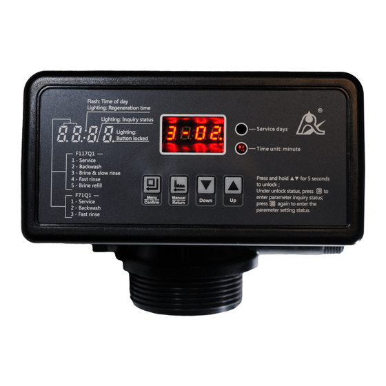
- Page 22 MODEL:F67Q/F71Q/F68Q/F69Q/F116Q/F117Q A. Button lock indicator When the fourth decimal point of digital tube turns it indicates buttons are locked. At this moment, pressing any single button will not work (No operation in one minute, the fourth decimal point of the digital tube will light on and lock the buttons).
- Page 23 MODEL:F67Q/F71Q/F68Q/F69Q/F116Q/F117Q Press and hold both for 5 seconds to unlock the buttons. In program set mode, press to return to program inquiry mode; in program inquiry mode, press to return to menu mode. Press while adjusting the values, then it will return to program ...
- Page 24 MODEL:F67Q/F71Q/F68Q/F69Q/F116Q/F117Q 2.2. Basic Setting & Usage (F116Q3 A-01 as example) A. Parameter specifications Factory Parameter Function Indicator Instruction Default set range 00:00~ When use, enquiry and set,the time of Time of Day ":"Flashes Random 23:59 day ":" flashes. Regeneration 00:00~ ":"...
- Page 25 MODEL:F67Q/F71Q/F68Q/F69Q/F116Q/F117Q Regeneration treated water does not drop to zero Days (0). b-01 : Signal turn when Output regeneration started and shut off at Control b-01 01 or 02 the end of regeneration. Mode b-02 : Signal available only in intervals of each status. B.
- Page 26 MODEL:F67Q/F71Q/F68Q/F69Q/F116Q/F117Q shows as F/C; In Fast Rinse status, it shows as figure G/C; In Brine Refill status, it shows as figure H/C. In each status, every figure shows 15 seconds. Above displays are taking the Meter Type F116Q3 A-01 for example. For the Time Clock Type, it shows the rest days, such as 1-03D.
- Page 27 MODEL:F67Q/F71Q/F68Q/F69Q/F116Q/F117Q C. Usage After the accomplishment of installation, parameter setting and trial running by the professional, the valve can be put into use. In order to ensure that the quality of outlet water can reach the requirements, the user should complete the below work: ①...
- Page 28 MODEL:F67Q/F71Q/F68Q/F69Q/F116Q/F117Q modify the settings, you can refer to the professional application specifications.
- Page 29 MODEL:F67Q/F71Q/F68Q/F69Q/F116Q/F117Q 3. Applications 3.1. Flow Chart A. Filter...
- Page 30 MODEL:F67Q/F71Q/F68Q/F69Q/F116Q/F117Q Remark: F68Q, F69Q working process: Service → Backwash → Brine & Slow Rinse (Up-flow Regeneration ) → Brine Refill → Fast Rinse → Service. F117Q, F116Q working process: Service → Backwash → Brine & Slow Rinse (Down-flow Regeneration ) → Fast Rinse → Brine Refill → Service. 3.2.
- Page 31 MODEL:F67Q/F71Q/F68Q/F69Q/F116Q/F117Q The main functions on main control board: Function Application Explanation Used in strictly requirements regarding no Outlet solenoid hard water flowing from outlet or control valve Signal output the liquid level in water tank. connector Increase pressure for regeneration or b-01 washing.
- Page 32 MODEL:F67Q/F71Q/F68Q/F69Q/F116Q/F117Q Instruction: If system requires no hard water to flow from outlet in regeneration cycle (Mainly for no hard water flows out when valve is switching or valve in backwash or brine drawing status), a solenoid valve could be installed on outlet, the wiring refers to Figure 3-1.
- Page 33 MODEL:F67Q/F71Q/F68Q/F69Q/F116Q/F117Q Function: When inlet pressure is high, install a solenoid valve on inlet to ensure valve switching properly. When valve is exactly in status of Service, Backwash, Brine & Slow Rinse, Fast Rinse and Brine Refill, solenoid valve is open. When valve is switching, solenoid valve is closed, no water flows into valve to ensure valve switching properly.
- Page 34 When valve in regeneration cycle, no matter what water condition water tank, open the pump to make sure there is water on inlet. As Runxin valve no water passes outlet in regeneration cycle, it ensures no water fill into brine tank.
- Page 35 MODEL:F67Q/F71Q/F68Q/F69Q/F116Q/F117Q 4) Control Inlet Booster Pump (Set as b-01 or as b-02) Instruction: If inlet water pressure is less than 0.15MPa, which makes rinse drawing difficult, a booster pump is suggested to be installed on inlet. Set Control mode as b-01. When system in regeneration cycle, booster pump is open, the wiring refers to Figure 3-7.
- Page 36 MODEL:F67Q/F71Q/F68Q/F69Q/F116Q/F117Q B. Interlock Instruction: In the parallel water treatment system, it ensures only one valve in regeneration or washing status and (n-1) valves in service, that is, realizing the function of supplying water simultaneously and regenerating individually, the wiring refers to Figure 3-9. In the series water treatment system (Second grade Na Exchanger or RO pre-treatment system), it ensures only one valve in regeneration or washing...
- Page 37 MODEL:F67Q/F71Q/F68Q/F69Q/F116Q/F117Q Use interlock cable to connect the black socket of one valve with the blue socket of another valve in series. One system with several valves, if interlock cable is disconnected, the system is divided into two individual system. C. Double (Multiple) Valves, Supply Water Simultaneously and Regenerate Separately It only needs to connect the or more valves by interlock cables.
- Page 38 MODEL:F67Q/F71Q/F68Q/F69Q/F116Q/F117Q Filter Filtering Backwash Filtering Backwash Material Flow Rate Flow Rate Flow Rate Flow Rate φ180×1130 φ205×1300 φ255×1390 φ300×1390 φ355×1670 φ400×1670 Attention: the filtering flow rate of carbon filter is calculated based on the 12m/h operation rate; the backwash flow rate is calculated based on the 10L/(m *s) backwash intensity;...
- Page 39 MODEL:F67Q/F71Q/F68Q/F69Q/F116Q/F117Q Control Resin Flow Brine Tank The Minimum Salt Injector Tank Size Volume Rate Size Consumption for Valve (mm) Model (t/h) (mm) Regeneration(Kg) Model φ205×1300 φ390×810 4.00 6301 φ255×1390 φ390×810 6.00 6303 F69Q φ300×1650 φ450×940 9.00 6304 φ355×1650 2.5 φ500×1060 15.00 6306 φ400×1650...
- Page 40 MODEL:F67Q/F71Q/F68Q/F69Q/F116Q/F117Q B. Flow Rate Characteristic 1) Pressure-flow rate curve...
- Page 41 MODEL:F67Q/F71Q/F68Q/F69Q/F116Q/F117Q...
- Page 42 MODEL:F67Q/F71Q/F68Q/F69Q/F116Q/F117Q...
- Page 43 MODEL:F67Q/F71Q/F68Q/F69Q/F116Q/F117Q 2) Injector parameter table F68Q, F69Q: Draw Rate(L/M) Inlet Pressure F69Q F68Q 6301 6303 6304 6306 6307 6308 Coffee Yellow Blue Black Purple 0.15 1.47 2.30 2.80 4.03 4.74 5.24 0.20 1.51 2.60 3.30 4.67 5.46 5.99 0.25 1.59 2.92 3.71 5.07...
- Page 44 MODEL:F67Q/F71Q/F68Q/F69Q/F116Q/F117Q 3) Configuration for Standard Injector and Drain Line Flow Control F68Q, F69Q: Draw Slow Backwash/ Tank Control Injector Injector Rate Rinse Fast Rinse BLFC Optional DLFC Valve Dia. Mode Color Model 8468076, 8468075, 8468057, 8468056, 846804 6301 Coffee 1.76 0.92 7.50 8468052 (Standard).
- Page 45 MODEL:F67Q/F71Q/F68Q/F69Q/F116Q/F117Q F116Q,F117Q: Draw Slow Backwash/Fast Tank Control Injector Injector Rate Rinse Rinse Dia. BLFC Optional DLFC Valve Mode Color Mode L/m L/m 175~ 8468076, 8468075, 8468057, 8468056, 6303 Yellow 2.75 1.66 8468042 7.33 8468052, 8468053 (Standard). 225~ 8468076, 8468075, 8468057, 8468056, 6304 Blue 3.33 2.18...
- Page 46 MODEL:F67Q/F71Q/F68Q/F69Q/F116Q/F117Q...
- Page 47 MODEL:F67Q/F71Q/F68Q/F69Q/F116Q/F117Q 3.4 Parameter settlement ① Service Time T1 Water Treatment Capacity: ×K÷Y Hardness of Inlet Water, mmol/L. Exchange factor, mmol/L, 400~1000. Down-flow regeneration, take 400~ 750; Up-flow regeneration, take 450 ~ 1000. If the inlet water hardness is higher, the factor is smaller.
- Page 48 MODEL:F67Q/F71Q/F68Q/F69Q/F116Q/F117Q In this formula,V ——Resin volume (m The brine tank brine refill speed is related to the inlet pressure. The real refill time should be 1 to 2 minutes longer than the calculated time in order to refill enough water in the brine tank. (The brine tank should be ⑤...
- Page 49 MODEL:F67Q/F71Q/F68Q/F69Q/F116Q/F117Q application. 3.5 Parameter Enquiry and Setting A. Parameter Enquiry When the fourth decimal point of the digital tube turning press and hold both for 5 seconds to unlock the button; then press until the third decimal point of digital tube turned on, enter to program...
- Page 50 MODEL:F67Q/F71Q/F68Q/F69Q/F116Q/F117Q B. Parameter Setting In program inquiry mode, press and enter into program set mode. Press can adjust the value.
- Page 51 MODEL:F67Q/F71Q/F68Q/F69Q/F116Q/F117Q C. The steps of parameter setting (Take F117Q3 A-01 for Example) Item Process steps Symbol 1. In time of day viewing status, Press to enter program set mode, both hour value and “:” flash, press Time of to adjust the hour value; 2.
- Page 52 MODEL:F67Q/F71Q/F68Q/F69Q/F116Q/F117Q 1. In brine & slow rinse time viewing status, press Brine & enter program set mode. Brine & slow rinse time value Slow flashes, press to adjust the brine & slow rinse Rinse time; Time 2. Press finish adjustment, press to return.
- Page 53 MODEL:F67Q/F71Q/F68Q/F69Q/F116Q/F117Q Press continuously until in service status, the digital ③ display area shows:4-12M; ④ Press , 12 flashes; ⑤ Press continuously until 12 change to 15; ⑥ Press again and hear a sound “Di” , the frame stop flickering,the program returns to enquiry status.;...
- Page 54 MODEL:F67Q/F71Q/F68Q/F69Q/F116Q/F117Q 3.6 Trial Running After installing the multi-functional flow control valve on the resin tank with the connected pipes, as well as setting up the relevant parameters, please conduct the trail running as follows: A. Close inlet/outlet valve B and Valve C, open bypass valve A, clean the impurity in the pipe, and then close bypass valve A (as Figure 1-3).
- Page 55 MODEL:F67Q/F71Q/F68Q/F69Q/F116Q/F117Q all positions, and ensure there is no resin leakage. The time of Backwash, Brine & Slow Rinse, Fast Rinse and Brine Refill status can be set and executed according to the calculation in the formula or suggested from the control valve suppliers.
- Page 56 MODEL:F67Q/F71Q/F68Q/F69Q/F116Q/F117Q 3.7 Trouble-Shooting A. Control Valve Fault Problem Cause Correction A. Electrical service to unit A. Assure permanent electrical has been interrupted. service (Check fuse, plug, pull 1. Softener B. Regeneration cycles set chain or switch). fails to incorrect. B. Reset regeneration cycles. regenerate.
- Page 57 MODEL:F67Q/F71Q/F68Q/F69Q/F116Q/F117Q A. Setting the appropriate amount A. Improper salt setting. 5. Unit used of salt for primary regeneration. B. Excessive water in brine much B. See problem No.6. tank. salt. Control Valve Fault (Continued) A. Overlong refilling time. A. Reset correct refilling time. B.
- Page 58 MODEL:F67Q/F71Q/F68Q/F69Q/F116Q/F117Q brine. faulty. C. Check and find the reason. C. Air in resin tank. D. Clean the floccules in resin D. Floccules in resin tank tank. during up-flow regeneration. A. Foreign material in valve which makes valve can’t be A. Clean foreign material in valve closed completely.
- Page 59 MODEL:F67Q/F71Q/F68Q/F69Q/F116Q/F117Q B. Controller Fault Problem Cause Correction A. Replace control board. A. Control board is faulty. B. Check and replace 1. All indictors B. Transformer damaged. transformer. display on front C. Electrical service is not C. Check and adjust panel. stable.
- Page 60 MODEL:F67Q/F71Q/F68Q/F69Q/F116Q/F117Q 5447018 Flow Meter 5457002 Animated Connector 5447018 Flow Meter 5457002 Animated Connector Item Quan Item Description Part No. Description Part No. tity ntity Animated Nut 8945001 Animated Nut 8945001 O-ring 8378081 O-ring 8378081 Impeller 5115022 Clip 8270004 supporter Impeller 5436010 Connector 8458038...
- Page 61 MODEL:F67Q/F71Q/F68Q/F69Q/F116Q/F117Q 5447020 Flow Meter 5457003 Animated Connector 5447020 Flow Meter 5457003 Animated Connector Item Quan Item Description Part No. Description Part No. tity ntity Connector 8458014 Connector 8458014 O-ring 8378064 O-ring 8378064 Impeller 5115023 Clip 8270005 supporter Impeller 5436013 Connector 8458039 Impeller 5115024...
- Page 62 MODEL:F67Q/F71Q/F68Q/F69Q/F116Q/F117Q Construction figure of F67Q3:...
- Page 63 MODEL:F67Q/F71Q/F68Q/F69Q/F116Q/F117Q F67Q3 Valve Body Components and No. doesn't have No.17, 30 and 31, [F67Q1 and change No. 10 from 8865174 (630) to 8865175 (631)] Item Description Part No. anti Description Part No. anti 638601 O-ring 73×5.3 8378143 Probe Wire Screw, Cross 890901 O-ring 25.8×2.65 8378078...
- Page 64 MODEL:F67Q/F71Q/F68Q/F69Q/F116Q/F117Q Construction figure of F68Q3:...
- Page 65 MODEL:F67Q/F71Q/F68Q/F69Q/F116Q/F117Q F68Q3 Valve Body Components and No. doesn't have No.16, 30 and [F68Q1 31, and change No. 9 from 8865174 (630) to 8865175 (631)] Description Part No. anti Description Part No. anti O-ring 73×5.3 8378143 Moving Disk 8459078 O-ring 25.8×2.65 8378078 Fixed Disk 8469079...
- Page 66 MODEL:F67Q/F71Q/F68Q/F69Q/F116Q/F117Q Moving Seal Ring 8370001 O-ring 7.5×1.8 8378016...
- Page 67 MODEL:F67Q/F71Q/F68Q/F69Q/F116Q/F117Q Construction figure of F69Q3:...
- Page 68 MODEL:F67Q/F71Q/F68Q/F69Q/F116Q/F117Q F69Q3 Valve Body Components and No. doesn't have No.18, 31 and [F69Q1 32, and change No. 10 from 8865176 (632) to 8865177 (633)] Item Description Part No. anti Description Part No. ntity 837814 837005 O-ring 73×5.3 Moving Seal Ring 837807 845901 O-ring 25.8×2.65...
- Page 69 MODEL:F67Q/F71Q/F68Q/F69Q/F116Q/F117Q ST2.9×16 638003 845400 Locating Board Nozzle, Injector 809200 846700 Throat, Injector Fitting Nut 837810 800801 24 O-ring 50.39×3.53 Injector Body Anti-friction 821601 837801 O-ring 10.82×1.78 Washer 825800 837801 Shaft O-ring 7.5×1.8...
- Page 70 MODEL:F67Q/F71Q/F68Q/F69Q/F116Q/F117Q Construction figure of F71Q3:...
- Page 71 MODEL:F67Q/F71Q/F68Q/F69Q/F116Q/F117Q F71Q3 Valve Body Components and No. doesn't have No.16, 28 and 29, [F71Q1 and change No. 8 from 8865176 (632) to 8865177 (633)] Item Description Part No. anti Description Part No. ntity O-ring 73×5.3 8378143 Probe Wire 6386014 Screw, Cross 2 O-ring 25.8×2.65 8378078 8909013 ST3.9×13...
- Page 72 MODEL:F67Q/F71Q/F68Q/F69Q/F116Q/F117Q Construction figure of F116Q3:...
- Page 73 MODEL:F67Q/F71Q/F68Q/F69Q/F116Q/F117Q F116Q3 Valve Body Components and No. doesn't have No.16, 30 and [F116Q3 31, and change No. 9 from 8865174 (630) to 8865175 (631)] Description Part No. anti Description Part No. ntity O-ring 73×5.3 8378143 Moving Disk 8459078 O-ring 25.8×2.65 8378078 Fixed Disk 8469079...
- Page 74 MODEL:F67Q/F71Q/F68Q/F69Q/F116Q/F117Q Moving Seal Ring 8370001 O-ring 7.5×1.8 8378016...
- Page 75 MODEL:F67Q/F71Q/F68Q/F69Q/F116Q/F117Q Construction figure of F117Q3:...
- Page 76 MODEL:F67Q/F71Q/F68Q/F69Q/F116Q/F117Q F117Q3 Valve Body Components and No. doesn't have No.18, 31 [F117Q1 and 32, and change No. 10 from 8865176 (632) to 8865177 (633)] Item Description Part No. anti Description Part No. ntity 837814 837005 O-ring 73×5.3 Moving Seal Ring 837807 845907 O-ring 25.8×2.65...
- Page 77 MODEL:F67Q/F71Q/F68Q/F69Q/F116Q/F117Q ST2.9×9.5 638003 845400 Locating Board Nozzle, Injector 809200 846700 Throat, Injector Fitting Nut 837810 800801 24 O-ring 50.39×3.53 Injector Body Anti-friction 821601 837801 O-ring 10.82×1.78 Washer 825800 837801 Shaft O-ring 7.5×1.8...
- Page 78 MODEL:F67Q/F71Q/F68Q/F69Q/F116Q/F117Q 4. Warranty Card Dear client: This warranty card is the guarantee proof of Runxin brand multi-functional flow control valve. It is kept by client self. You could get the after-sales services from the supplier which is appointed by Runxin manufacturer.
- Page 79 Ground-water □ Tap Capacity Water □ Brine & Slow Rinse Time Brine Refill Time Fast Rinse Time Problem Description WENZHOU RUNXIN MANUFACTURING MACHINE CO., LTD. ADD.: NO.169, RUNXIN ROAD, SHANFU TOWN, WENZHOU, ZHEJIANG, CHINA. TEL.:0086-577-88630038, 88576512, 85956057 FAX:0086-577-88633258 E-MAIL: sales@run-xin.com http://www.run-xin.com Rev.A.1902...
- Page 80 MODEL:F67Q/F71Q/F68Q/F69Q/F116Q/F117Q...
Need help?
Do you have a question about the 55504 and is the answer not in the manual?
Questions and answers