Table of Contents
Advertisement
Quick Links
Advertisement
Table of Contents

Subscribe to Our Youtube Channel
Related Manuals for SIGLENT SSG5000A


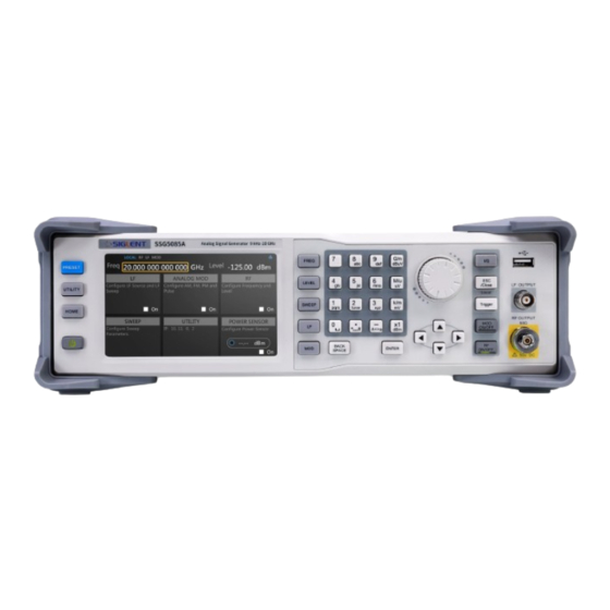
Summary of Contents for SIGLENT SSG5000A
- Page 1 SSG5000A Signal Generator Service Manual SM0805A-E01A SSG3000A Service Manual 1...
-
Page 3: Guaranty And Declaration
Declaration ◆ SIGLENT products are protected by patent law worldwide. ◆ SIGLENT reserves the right to modify or change parts of or all the specifications or pricing policies at company’s sole decision. ◆ Information in this publication replaces all previously corresponding material. -
Page 4: General Safety Summary
So keep well ventilated and inspect the intake and fan regularly. Avoid Exposed Circuit or Components Do not touch exposed contacts or components when the power is on. Do Not Operate Without Covers Do not operate the instrument with covers or panels removed. SSG5000A Service Manual... - Page 5 In order to avoid short circuiting to the interior of the device or electric shock, please do not operate the instrument in a humid environment. Do Not Operate in an Explosive Atmosphere. In order to avoid damage to the device or personal injury, it is important to operate the device away from an explosive atmosphere. SSG5000A Service Manual...
-
Page 6: Safety Terms And Symbols
WARNING: Indicates an injury or hazard that may not immediately happen. CAUTION: Indicates that a potential damage to the instrument or other property might occur. Symbols on the product. These symbols may appear on the product: Hazardous Protective Warning Earth Chassis Voltage Ground Ground SSG5000A Service Manual... -
Page 7: Table Of Contents
Assembly Procedures ........................35 Safety Considerations ......................... 35 List of Modules ..........................36 Required Tools ..........................36 Disassembly Procedures ......................36 Remove the Outer Cover ..................... 37 Remove the Channel plate Module ..................38 Remove the Power Module ....................39 SSG5000A Service Manual... - Page 8 Remove the frequency multiplication plate module ............. 40 Remove the Mechanical attenuator module ................ 41 Remove the Control Board ....................42 Remove the Main Board ...................... 43 Remove the front panel ....................... 44 Remove the LCD and Keyboard ..................45 Contact SIGLENT..........................46 SSG5000A Service Manual...
-
Page 9: Preparation Information
User Manual. Power-on Inspection The normal operating voltage for SSG5000A series signal generator is in the range of 100-240 VRMS, 50/60Hz or 100-120 VRMS, 400Hz. Please use the power cord provided in the accessories to connect the instrument to the power source as shown in the figure below. -
Page 10: Interface Test
Figure 3 Rear Panel Interface Test The SSG5000A series signal generator is designed with three standard interfaces: USB Host, USB Device and LAN. Being connected to other instruments via these interfaces enables the signal generator to achieve additional capabilities. To ensure the signal generator is working properly, it is recommended to test the interfaces first. -
Page 11: Usb Device Test
Download and install National Instruments NI MAX software by following the installation instructions provided by National Instruments. Connect the signal generator USB Device port and the computer with an USB cable. Run NI MAX software. Click “Device and interface” at the upper left corner of the NI software SSG5000A Service Manual... -
Page 12: Lan Port Test
Then click the “Input/Output” option button on the VISA Test Panel and click the “Query” option button to view the Read operation information. LAN Port Test To test if the LAN interface is working normally. Tools: ⚫ A computer with functional LAN interface ⚫ A standard LAN cable Steps: SSG5000A Service Manual... - Page 13 “Network Devices”, “Add Network Device”, and select “VISA TCP/IP Resource” as shown: Select Manual Entry of LAN instrument, click “Next”, and enter the IP address as shown in the following figures. Click Finish to establish the connection. SSG5000A Service Manual...
- Page 14 Note: Leave the LAN Device Name BLANK or the connection may fail. After a brief scan, the connection will be shown under Network Devices: SSG5000A Service Manual...
- Page 15 Click the “Input/Output” option button on the VISA Test Panel and click the “Query” option button to view the Read operation information. Note: The *IDN? Command (known as the Identification Query) should return the instrument manufacturer, instrument model, serial number, and other identification information. SSG5000A Service Manual...
-
Page 16: Performance Verification Test
R&S NRP40T Frequency Counter 10 MHz 53220A N-2.92mm Cable 20GHz BNC Cable 2 GHz 10 MHz output accuracy test Specification Reference frequency 10.000000 MHz Initial calibration accuracy < 100 ppb Test Connection Diagram 10MHz OUT 53220A SSG5000A SSG5000A Service Manual... -
Page 17: Absolute Amplitude Accuracy Test
13.6 GHz < f ≤ 20 GHz ≤ 1dB ≤ 0.7 dB ≤ 0.9 dB ≤ 1.1 dB ≤ 2 dB Test Devices Power Meter × 1 SMA-2.92mm Adaptor × 1 Dual-BNC Cable × 1 Signal generator × 1 SSG5000A Service Manual... - Page 18 Figure 6 Absolute amplitude accuracy connections Test Procedures Connect the RF output terminal of the SSG5000A with the power meter, as shown in Figure 6 (a). Set the SSG5000A to output a sine waveform with -10 dBm amplitude. Then modify the output frequency of the SSG5000A according to Table 2 and enable the RF output.
- Page 19 Connect the [ RF OUTPUT ] terminal of the SSG5000A with the input terminal of the signal analyzer using a dual-N cable as shown in Figure 6 (b). Configure the signal analyzer: Set the self-calibration to normal and perform all of the calibration items Select the external frequency reference input.
- Page 20 Table 2 Output Frequency of the SSG5000A Output Frequency 1.33 51.33 1.933 2.433 2.933 3.933 4.933 5.933 7.933 9.433 11.933 13.933 15.933 17.933 19.933 Note: When the frequency of the signal measured is less than 10 MHz, make certain the signal analyzer is in the DC coupling mode to ensure the measurement accuracy.
- Page 21 Accuracy 103 kHz 1.33 MHz 51.33 MHz 533 MHz 1.933 GHz 2.433 GHz 2.933 GHz 3.933 GHz 4.933 GHz < 0.7 5.933 GHz 7.933 GHz 9.933 GHz 11.933 GHz 13.933 GHz 15.933 GHz 17.933 GHz 19.933 GHz SSG5000A Service Manual...
- Page 22 Accuracy 103 kHz 1.33 MHz 51.33 MHz 533 MHz 1.933 GHz 2.433 GHz 2.933 GHz 3.933 GHz 4.933 GHz < 0.7 5.933 GHz 7.933 GHz 9.933 GHz 11.933 GHz 13.933 GHz 15.933 GHz 17.933 GHz 19.933 GHz SSG5000A Service Manual...
-
Page 23: Second Harmonics
RF INPUT N-2.92mm Cable Test Procedures Synchronize the SSG5000A and signal analyzer. Connect the RF output terminal of the SSG5000A with the RF input terminal of the signal analyzer. Configure the SSG5000A: Set the output frequency according to the test record form as shown below... - Page 24 Preset. Set the input attenuation to auto. Set the reference level to the SSG5000A power plus 2dBm. Switch the preamp to off. Set the center frequency to the SSG5000A frequency. Set the span to 5 kHz. Set the resolution bandwidth to 100 Hz.
-
Page 25: Internal Am Modulation Test
< 4 % of m setting+1 % =1 kHz, m≤30 %, AM Distortion <3 % (typ.) level=0 dBm Note: m represents the AM depth. Test Devices Signal Analyzer × 1 Dual-BNC Cable × 1 N-2.92mm Cable × 1 SSG5000A Service Manual... - Page 26 N-2.92mm Cable Test Procedures Synchronize the SSG5000A and signal analyzer. Connect the RF output terminal of the SSG5000A with the RF input terminal of the signal analyzer as shown in above figure. Configure the SSG5000A: Set the frequency to 1 GHz.
-
Page 27: Internal Fm Modulation Test
< 2% of m setting+20 Hz =1 kHz, FM Distortion < 0.5 % (nom.) m=N*1 MHz Note: Please refer to the value of N in the “Frequency Bands” section of the SSG5000A Data Sheet. m represents the FM deviation. SSG5000A Service Manual... - Page 28 N-2.92mm Cable Test Procedures Synchronize the SSG5000A and signal analyzer. Connect the RF output terminal of the SSG5000A with the RF input terminal of the signal analyzer as shown in above figure. Configure the SSG5000A: Set the frequency to 1 GHz.
-
Page 29: Internal Φm Modulation Test
< 0.5 % (nom.) Internal ΦM modulation test Specification Phase Modulation Modulation source internal, external, internal + external Maximum ΦM deviation *5 rad Resolution of m setting 0.1 % of m setting or 0.01 rad, whichever is larger SSG5000A Service Manual... - Page 30 ΦM Distortion =1 kHz, deviation ≤ N*5 rad < 0.5 % (nom.) Note: Please refer to the value of N in the “Frequency Bands” section of the SSG5000A Data Sheet. m represents the ΦM deviation. Test Devices Signal Analyzer × 1 Dual-BNC Cable ×...
- Page 31 Then, compare the calculation results with the specifications. Test Record Form SSG5000A Output Test Item Measurement Calculated Limit Pass/ Fail Frequency Result < 2% of ΦM Accuracy setting + 0.05 1 GHz ΦM Distortion < 0.5 % (nom.) SSG5000A Service Manual...
-
Page 32: Pulse Modulation Test
N-2.92mm Cable Test Procedures Synchronize the SSG5000A and signal analyzer. Connect the RF output terminal of the SSG5000A with the RF input terminal of the signal analyzer as shown in above figure. Configure the SSG5000A: Set the frequency to 1 GHz. - Page 33 Set the trigger mode to video trigger. Press Click to trigger on the display of the SSG5000A to start a pulse sweep and wait for the analyzer to finish a sweep. And then press Peak Search to locate the peak.
-
Page 34: Lf Ac Test
USB Cable × 1 Test Connection Diagram Test Procedures Connect the LF output terminal of the SSG5000A with the input terminal of the power sensor. Connect the [ USB ] connector of the SSG5000A with the USB interface of the power sensor as shown in figure above. -
Page 35: Lf Dc Test
Digital Multimeter × 1 Banana-to-single-BNC Cable × 1 Test Connection Diagram Banana to single BNC Cable Test Procedures Connect the LF output terminal of the SSG5000A with the Voltage input terminal of the Digital Multimeter as shown in figure above. SSG5000A Service Manual... - Page 36 Note: The output impedance of generator is 50Ω and the input impedance of DMM is high-z, so the measured value should divide by 2 to get an accurate value. Compare the measured voltage with the spec range shown in the table above. SSG5000A Service Manual...
-
Page 37: Assembly Procedures
Assembly Procedures This chapter describes how to remove the major modules from the SSG5000A signal generator. To install the removed modules or replace new modules, please follow the corresponding operating steps in reverse order. This chapter includes the following topics: ⚫... -
Page 38: List Of Modules
Custom screw hexagonal nut tool or long nose pliers Disassembly Procedures This section describes how to remove and install the modules listed above in the signal generator in detail. Complete disassembly will be best achieved using the following operating steps. SSG5000A Service Manual... -
Page 39: Remove The Outer Cover
Remove the screws as shown in figures above. Press the place of the outer cover as the arrow point in the figure and remove the outer cover from the machine. To install the outer cover, please perform the steps in reverse order. SSG5000A Service Manual... -
Page 40: Remove The Channel Plate Module
Disconnect the connecting line and the RF cable Remove the eleven screws located on the channel plate module. Next, remove the channel plate module. To install the channel plate module, please follow the steps in reverse order. SSG5000A Service Manual... -
Page 41: Remove The Power Module
Remove the Power Module power cable screw×4 Removal steps: Disconnect the power cable Remove the four screws located on the metal shell Next, remove the Power Module To install the Power Module, please follow the steps in reverse order. SSG5000A Service Manual... -
Page 42: Remove The Frequency Multiplication Plate Module
RF cable Removal steps: Disconnect the RF cable Remove the six screws located on the metal shell Next, remove the frequency multiplication plate Module To install the frequency multiplication plate Module, please follow the steps in reverse order. SSG5000A Service Manual... -
Page 43: Remove The Mechanical Attenuator Module
RF cable screw×4 Removal steps: Disconnect the RF cable Remove the four screws located on the metal shell Next, remove the mechanical attenuator module To install the mechanical attenuator module, please follow the steps in reverse order. SSG5000A Service Manual... -
Page 44: Remove The Control Board
Remove the Control Board Removal steps: Unlock the hook as show in the above figure Remove the control board SSG5000A Service Manual... -
Page 45: Remove The Main Board
Disconnect the screen cable connected to the main board module from the front module and RF cable. Remove the screws located on the main board. Remove the six nuts from the back BNC terminal. To install Main Board, please perform the steps in reverse order. SSG5000A Service Manual... -
Page 46: Remove The Front Panel
Remove the front panel Removal steps: Remove the eight screws on the rubber feet Remove the four screws located on the front panel. To install the front panel, please perform these steps in reverse order. SSG5000A Service Manual... -
Page 47: Remove The Lcd And Keyboard
SCREW × 4 Removal steps: Remove the thirteen screws on the keyboard. Remove the four screws located on the edge of the display module. Disconnect the cable that connects the keyboard and the channel board. Separate the modules carefully. SSG5000A Service Manual... -
Page 48: Contact Siglent
Contact SIGLENT Headquarters: SIGLENT Technologies Co., Ltd Add: Bldg No.4 & No.5, Antongda Industrial Zone, 3rd Liuxian Road, Bao'an District, Shenzhen, 518101, China Tel: + 86 755 3688 7876 Fax: + 86 755 3359 1582 Email: sales@siglent.com Website: int.siglent.com North America:... - Page 49 DC power supplies, electronic loads and other general purpose test instrumentation. Since its first oscilloscope was launched in 2005, SIGLENT has become the fastest growing manufacturer of digital oscilloscopes. We firmly believe that today SIGLENT is the best value in electronic test & measurement. Headquarters: SIGLENT Technologies Co., Ltd...
Need help?
Do you have a question about the SSG5000A and is the answer not in the manual?
Questions and answers