
Related Manuals for SIGLENT SSG5000A


Summary of Contents for SIGLENT SSG5000A
- Page 1 SSG5000A RF Signal Generator User Manual SSG5000A RF Signal Generator User Manual User Manual 0805A -E01A SSG5000A User Manual...
- Page 2 Declaration ◆ SIGLENT products are protected by patent law worldwide. ◆ SIGLENT reserves the right to modify or change parts of or all the specifications or pricing policies at company’s sole decision. ◆ Information in this publication replaces all previously corresponding material.
-
Page 3: General Safety Summary
SSG5000A RF Signal Generator User Manual General Safety Summary Carefully read the following safety precautions to avoid any personal injury or damage to the instrument and any products connected to it. To avoid potential hazards, please use the instrument as specified. - Page 4 SSG5000A RF Signal Generator User Manual Avoid Exposed Circuit or Components Do not touch exposed contacts or components when the power is on. Do Not Operate Without Covers Do not operate the instrument with covers or panels removed. Use Only the Specified Fuse.
-
Page 5: Safety Terms And Symbols
SSG5000A RF Signal Generator User Manual The responsible body or operator should refer to the instruction manual to preserve the protection afford by the equipment. If the equipment is used in a manner not specified by the manufacturer, the protection provided by the equipment may be impaired. -
Page 6: Working Environment
SSG5000A RF Signal Generator User Manual Working Environment Environment For indoor use only Rated voltage/frequency 100 V-240 V(± 10%), 50/60 Hz 100 V-120 V(± 10%), 400 Hz Rated input power Temperature Operating: 0℃ to +50℃ Non-operation: -20℃ to +70℃ Humidity Operating: 0℃... -
Page 7: Cleaning
SSG5000A RF Signal Generator User Manual done to limit the transient voltage to the corresponding low level. Installation (overvoltage) category II refers to the local power distribution level which is applicable to equipment connected to the AC line (AC power). -
Page 8: Garantie Et Déclaration
◆ Les produits SIGLENT sont protégés par le droit des brevets dans le monde entier ◆ SIGLENT se réserve le droit de modifier ou de changer des parties ou toutes les spécifications ou politiques de prix à la seule décision de l'entreprise ◆... - Page 9 SSG5000A RF Signal Generator User Manual Résumé de la sécurité générale Lisez attentivement les précautions de sécurité suivantes pour éviter toute blessure corporelle ou tout dommage à l'instrument et aux produits qui y sont connecté s. Pour éviter les dangers potentiels, veuillez utiliser l'instrument comme spécifié.
- Page 10 SSG5000A RF Signal Generator User Manual Ne pas utiliser sans couvercles N'utilisez pas l'instrument avec les couvercles ou les panneaux retirés. Utilisez uniquement le fusible spé cifié. Gardez les surfaces du produit propres et sèches. Pour éviter l'influence de la poussière et / ou de l'humidité dans l'air, veuillez garder la surface de l'appareil propre et sèche.
-
Page 11: Termes Et Symboles De Sécurité
SSG5000A RF Signal Generator User Manual Termes et symboles de sécurité Termes utilisés dans ce manuel: DANGER: indique une blessure ou un danger pouvant survenir immédiatement. AVERTISSEMENT: indique une blessure ou un danger qui peut ne pas se produire immédiatement. -
Page 12: Nettoyage
SSG5000A RF Signal Generator User Manual Humidité Fonctionnement: 0 ℃ à + 30 ℃ Non-fonctionnement: 30 ℃ à + 50 ℃, ATTENTION Pour éviter un court-circuit à l'intérieur de l'instrument ou un choc électrique,veuillez ne pas utiliser dans un environnement humide. -
Page 13: Ssg5000A Overview
Manual SSG5000A Overview The SIGLENT SSG5000A series is a bench top RF signal source, with an output frequency range from 9 kHz to 20 GHz. It features light weight, small size, and convenient interface make it ideal for R&D, education, production and maintenance. -
Page 14: Table Of Contents
SSG5000A RF Signal Generator User Manual Contents Guaranty and Declaration ....................... I General Safety Summary ....................... II Safety Terms and Symbols ......................IV Working Environment ........................V Cleaning ............................VI Garantie et déclaration ......................... VII Termes et symboles de sécurité ....................X Environnement de travail ....................... - Page 15 SSG5000A RF Signal Generator User Manual Trigger Mode ....................31 Point Trigger ..................... 32 Trigger Slope ....................33 Analog Modulation ....................34 Amplitude Modulation (AM) ................34 Frequency Modulation (FM) ................37 Phase Modulation (PM) ..................41 Pulse Modulation (PULSE) ................44 LF Setting .........................
- Page 16 SSG5000A RF Signal Generator User Manual Chapter 6 Service and Support ....................99 Service Summary..................... 99 Contact Us ......................100 SSG5000A User Manual...
-
Page 17: Chapter 1 Quick Start
SSG5000A RF Signal Generator User Manual Chapter 1 Quick Start Subjects in this chapter: ◆ Appearance size ◆ Preparing for Use ◆ The Front Panel ◆ Rear Panel ◆ User interface ◆ Touch operation ◆ Parameter setting ◆ Help information... -
Page 18: Appearance Size
SSG5000A RF Signal Generator User Manual 1.1 Appearance size Figure 1-1 Front View Figure 1-2 Top View Figure 1-3 Side View SSG5000A User Manual... -
Page 19: Preparing For Use
SSG5000A RF Signal Generator User Manual 1.2 Preparing for Use Adjust the Supporting Legs For benchtop operation, you may want to use the supporting legs. Adjust the supporting feet appropriately to tilt the RF signal source upwards. Figure 1-4 before adjusting... -
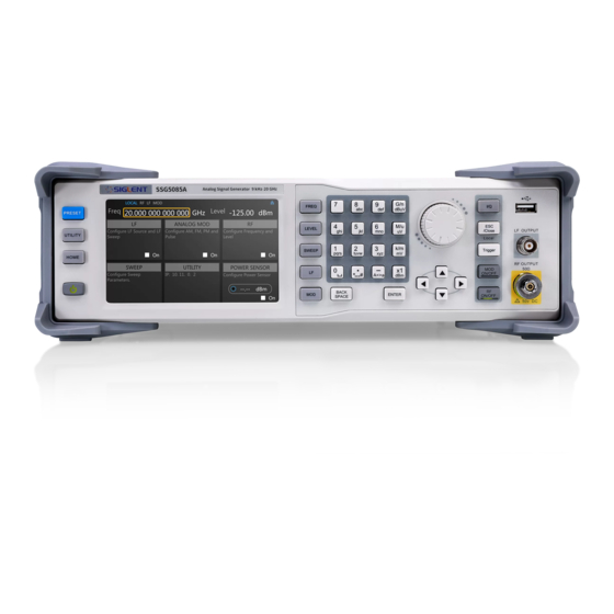
Page 20: The Front Panel
SSG5000A RF Signal Generator User Manual 1.3 The Front Panel Figure 1-7 the Front Panel Table 1-1 Front Panel Description Description Description Function key USB Host LF output RF output Knob Direction key Digital keyboard Touch screen display area Power button... -
Page 21: Front Panel Key Backlight
Set LF state, LF level, LF frequency and other related parameters. Set various modulation parameters (AM, FM, PM and PULSE). Set IQ related parameters (SSG5000A not support). ESC/Close During the parameter editing process, pressing this key will clear the input of the active function area and exit the parameter input state. -
Page 22: Digital Keyboard
SSG5000A RF Signal Generator User Manual RF ON/OFF When the RF signal is turned on, the backlight is on. If the RF signal output is turned off, the backlight will be dark. Digital keyboard The front panel of the RF signal source provides a numeric keypad (as shown below). The keyboard supports English uppercase and lowercase characters, numbers and common symbols (including decimal point, blank space, negative sign and !, @, #, $, %, ^, &, *),... - Page 23 SSG5000A RF Signal Generator User Manual frequency, press this key to set the unit as GHz. If the input is a time-related parameter, press this key to set the unit as ns. When setting the amplitude, press this key to set the unit as uV. When setting the frequency, press this key to set the unit as MHz.
-
Page 24: Front Panel Connectors
SSG5000A RF Signal Generator User Manual Front Panel Connectors Figure 1-9 front panel connectors LF (low frequency) output Output the low frequency signal. This is a BNC connection .The output can also be configured to source the modulation waveform for FM and PM modulation types. -
Page 25: Rear Panel
LAN interface Used to link the RF signal source to the computer or computer network, the SSG5000A is VXI-11 compliant, supports remote commands based on Socket and Telnet, and uses WEB for remote control. It can quickly build test systems with other standard equipment. - Page 26 SSG5000A RF Signal Generator User Manual The interface can be connected to a compatible computer and controlled by software on the host computer. EXT MOD INPUT Input BNC connection for an external modulation. 10MHz IN The [10MHz IN] and [10MHz OUT] connectors are commonly used to establish synchronization between multiple instruments.
- Page 27 SSG5000A RF Signal Generator User Manual 1) PULSE IN: When the pulse source is "Ext", it is used to input external pulse signals. 2) PULSE OUT: When the Pulse modulation source is "Int" and the pulse output switch is turned on, it is used to output the pulse signal generated by the internal generator.
-
Page 28: User Interface
SSG5000A RF Signal Generator User Manual 1.5 User interface Figure 1-11 User Interface Prompt status bar ⚫ Display LOCAL (local) or REMOTE (remote). When REMOTE is displayed, the instrument is being controlled by a remote computer and the front panel input will be locked .To unlock the front panel (enter LOCAL mode), press... -
Page 29: Touch Operation
SSG5000A RF Signal Generator User Manual RF output frequency setting. When the sweep type is "frequency" or "frequency & amplitude", the frequency scanning progress bar is displayed. RF level RF output level setting. When the sweep type is "amplitude" or "frequency & amplitude", the level scanning progress bar is displayed. -
Page 30: Parameter Setting
SSG5000A RF Signal Generator User Manual 1.7 Parameter setting arameter input can be performed through touch screen, keypad and digital keys, knob or direction keys. This section introduces an example of three parameter setting methods by setting the center frequency to 100 MHz. -
Page 31: Help Information
SSG5000A RF Signal Generator User Manual 1.8 Help information The built-in help system of RF signal source provides help information for each function and menu option on the front panel. ◆ Press UTILITY button and select Help. The center of the screen will pop up to help. -
Page 32: Chapter 2 Front Panel Operation
SSG5000A RF Signal Generator User Manual Chapter 2 Front Panel Operation This chapter describes in detail the function keys at the front panel and the associated functions. Subjects in this chapter: ◆ Frequency Setting ◆ Level Setting ◆ Sweep Setting ◆... -
Page 33: Frequency Setting
SSG5000A RF Signal Generator User Manual 2.1 Frequency Setting The value of the RF frequency is displayed in the header of the display (“Freq”). This field provides the direct input of the RF frequency. Alternatively, you can enter the RF frequency in the “Freq”... -
Page 34: Freq Offset
SSG5000A RF Signal Generator User Manual 2. Touch screen operation Click on RF-> FREQ->Frequency to enter the interface of RF output frequency setting. ⚫ Click the frequency parameter to pop up the keypad interface, and then click the number symbol in the keypad to change the value. Click the unit to modify the unit. -
Page 35: Phase Offset
SSG5000A RF Signal Generator User Manual Note: ⚫ The relationship between the RF output frequency, the display frequency and frequency offset is: Display frequency = RF output Frequency + Frequency offset ⚫ The difference value between the display frequency and the frequency offset is the actual RF output frequency, which must not exceed the instrument frequency output range. -
Page 36: Level Setting
SSG5000A RF Signal Generator User Manual Click the check mark to confirm the modified value and selected unit. Click on RF-> FREQ->Reset phase delta display to reset the phase offset to 0 deg. 2.2 Level Setting The value of the RF level is displayed in the header of the display (labeled “Level”). This field provides the direct input of the RF level value. -
Page 37: Level Setting
SSG5000A RF Signal Generator User Manual Level setting Setting the RF signal level Keypad operation: Press the LEVEL->Level to make the focus fall on this parameter item ⚫ Use the numeric keypad to input the desired value and press the unit button to select the desired unit. -
Page 38: Alc State
SSG5000A RF Signal Generator User Manual mark to confirm. ⚫ Press ENTER or press the knob to enter the parameter editing state, and then use the left and right direction keys to move the cursor to the desired position. Press the up and down direction keys, rotate the knob or press the numeric keypad to modify the value. -
Page 39: Flatness
SSG5000A RF Signal Generator User Manual Touch operation Click on RF-> LEVEL->ALC state to select ALC state. ALC has three functions: "Off", "On" and "Auto”: ● AUTO Automatically turn on or off the ALC function according to the equipment state. - Page 40 SSG5000A RF Signal Generator User Manual Press LEVEL->Flatness to make the focus fall on the flatness menu, then press the knob or ENTER key to switch flatness status. When opened, the status bar displays the blue UF letters. ⚫ Touch operation Click on RF->...
- Page 41 SSG5000A RF Signal Generator User Manual Press to empty the list. Recall Press to enter the file recall page, select and open existing flatness correction files. Please refer to " " for details. Save/Recall Save Press to enter the file save page, save the correction data in the list. Please refer to "...
- Page 42 SSG5000A RF Signal Generator User Manual state will be turned on or turned off automatically. ⚫ During filling the flatness list, the pop-up message will be shown as below. You should not remove the power sensor until the process is finished.
-
Page 43: Sweep Setting
Press SWEEP to enter RF sweep setting. Sweep State The sweep state is off by default. The signal generator SSG5000A offers three different RF sweep types: Freq, Level, and Freq & Level. Clicking the drop-down box of the sweep state to choose a sweep type: ⚫... -
Page 44: Step Sweep
SSG5000A RF Signal Generator User Manual the process. Step Sweep The step sweep state is on by default. Click the slide to switch the on-off state. Click to enter the parameter setting menu of step sweep. Note: The step sweep and list sweep are mutually exclusive. One will shut off automatically when the other is on. - Page 45 SSG5000A RF Signal Generator User Manual enter the table edit page of list sweep. Note: The List sweep and step sweep are mutually exclusive. One will shut off automatically when the other is on. As shown in the above figure, the table edit page consists of the operating buttons at the left and right of the page and the table on the middle of the page.
-
Page 46: Direction
Level: Indicates the level of the sweep point. Time: Indicates the dwell time of the sweep point. Direction Sweep direction state is “Up” by default. The SSG5000A provides two types: “Up” or “Down”. Click the drop-down box to enable the corresponding sweep direction. ⚫... -
Page 47: Trigger Mode
Trigger Mode The default trigger mode is “Auto”. The SSG5000A provides four types of trigger mode: “Auto”, “Key”, “Bus” and “Ext”. Click the drop-down box of the trigger mode to select the desired type: Auto: The default mode. -
Page 48: Point Trigger
SSG5000A RF Signal Generator User Manual Point Trigger The default point trigger mode is “Auto “. The SSG5000A provides four types of point trigger: “Auto”, “Key”, “Bus” and “Ext”. Click the drop-down box of point trigger mode to select the desired type: ⚫... -
Page 49: Trigger Slope
SSG5000A RF Signal Generator User Manual Trigger Slope When the trigger mode or the point trigger mode is “Ext”, you can select “Positive” or “Negative” as the trigger type. The default trigger type is “Positive”. Click the drop-down box to select the desired trigger edge: ⚫... -
Page 50: Analog Modulation
SSG5000A RF Signal Generator User Manual 2.4 Analog Modulation Amplitude Modulation (AM) Amplitude Modulation (AM) is a technique for delivering information by linearly varying the amplitude of an RF carrier signal. AM source can be selected as an internal source, external source or internal source + external source. - Page 51 Use both the internal and external modulation signals. This technique can be used to source dual tone AM. AM Shape The SSG5000A supports modulation waveforms for internal “Sine” and “Square” modulation sources. Select MOD->AM-> AM Shape, after setting AM Source to “Int” or “Int+Ext”, you can select AM waveform as “Sine” or “Square”.
- Page 52 SSG5000A RF Signal Generator User Manual AM Depth Set the modulation depth in percent. Select MOD->AM->AM Depth, and then set AM depth. ⚫ When the “Int” modulation source is selected, the AM modulation depth is set from 0.1% to 100%. The relationship between the modulation depth m and the carrier sideband level difference ΔP is satisfied: ΔP=6.02-20*lg (m)
-
Page 53: Frequency Modulation (Fm)
SSG5000A RF Signal Generator User Manual AM Sensitivity Display the AM depth unit offset which quantized by the amplitude of external signal. When the external signal is full scale, actual offset will be max. Specially, when the AM source is “Int+Ext”, the offsets caused by internal and external sources are evenly split. - Page 54 SSG5000A RF Signal Generator User Manual FM State Select MOD ->FM->FM State, to turn FM on or off. FM Source Select MOD ->FM-> FM Source to set “Int1”, “Int2”, “Int1 + Int2”, “Ext”, “Int1 + Ext” or “Dual”. The default is “Int1”.
- Page 55 SSG5000A RF Signal Generator User Manual FM Shape Select MOD->FM-> FM Shape. After setting to “Int” or “Int+Ext”, you can select FM waveform as “Sine” or “Square” or “Sawtooth” or “Triangle”. FM Rate Select MOD->FM-> FM Rate, you can set the FM rate.
- Page 56 SSG5000A RF Signal Generator User Manual FM Sensitivity Display the FM deviation unit offset which quantized by the amplitude of external signal. When the external signal is full scale, actual offset will be max. Specially, when the FM source is “Int1+Ext”, the offsets caused by internal and external sources are evenly split.
-
Page 57: Phase Modulation (Pm)
SSG5000A RF Signal Generator User Manual Phase Modulation (PM) Enter the PM interface Click the ANALOG MOD->PM in the main interface to enter the PM interface. Enter the MOD interface via the MOD button and switch to the PM modulation page. - Page 58 SSG5000A RF Signal Generator User Manual Use an external modulation signal. The external signal is input via the [EXT MOD INPUT] connector on the rear panel of the instrument. The modulated signal can be an arbitrary waveform. 3. Int + Ext Use both, the internal and external modulation signal;...
- Page 59 SSG5000A RF Signal Generator User Manual ⚫ When the modulation source selects “Int+Ext”, the set value is the maximum value of the total offset, the internal source accounts for 50%, and the external source accounts for 50%. RF output offset = set value × 0.5 + external input signal amplitude × external modulation sensitivity.
-
Page 60: Pulse Modulation (Pulse)
SSG5000A RF Signal Generator User Manual Pulse Modulation (PULSE) Pulse Modulation represents the process of modulating an RF carrier signal with a pulse signal as a modulation signal. Pulse State Select MOD->PULSE->Pulse State to turn Pulse on or off. Pulse Out Select MOD->PULSE->Pulse Out to turn Pulse Out on or off. - Page 61 Pulse Mode When the modulation source is “Int”, the SSG5000A provides three pulse modes: “Single”, “Double” and “Train”. The default is “Single”. Click the drop down box to select the pulse mode.
- Page 62 SSG5000A RF Signal Generator User Manual ⚫ Train: Multiple pulse signals in one pulse period. At this time, the pulse sequence setting item appears, and the two settings “Double Pulse Delay” and “#2 Width” are hidden. Note: This setting item will be hidden when the modulation source is “Ext”.
- Page 63 SSG5000A RF Signal Generator User Manual Double Pulse Delay The double pulse delay indicates the delay from the start of the first pulse to the start of the second pulse in a single cycle of the double pulse modulation signal. This parameter can be set by touching screen keyboard or pressing the front panel keypad.
- Page 64 SSG5000A RF Signal Generator User Manual Pulse Trigger The trigger mode defaults to “Auto”. The SSG5000A offers five pulse trigger types: “Auto”, “Key”, “Bus”, “Ext Trig” and “Ext Gate”. Click the drop-down box corresponding to the trigger mode to select the desired type.
- Page 65 SSG5000A RF Signal Generator User Manual Trigger Slope The default is “Positive”, click the drop-down box to switch the trigger slope. ⚫ Positive: Trigger a pulse when the positive slope of the external trigger signal arrives. ⚫ Negative: Trigger a pulse when the negative slope of the external trigger signal arrives.
- Page 66 SSG5000A RF Signal Generator User Manual As shown above, the pulse sequence edit page consists of the setting buttons and the middle table area: Click the button to automatically insert a new line on the next line where the current cursor is located.
- Page 67 SSG5000A RF Signal Generator User Manual and modify the sequence next step. Save Click the -> button to save the pulse sequence to file. Note: For details on loading/saving files, please refer to the related introduction in “ ”. Save/Recall...
- Page 68 SSG5000A RF Signal Generator User Manual levels in the direction is unchanged. The horizontal direction represents the high and low level duration of each pulse signal in the pulse sequence. You can use the zoom feature to observe different details of the waveform.
- Page 69 SSG5000A RF Signal Generator User Manual As shown above, in Advanced Mode, ⚫ By setting the On Time and Off Time parameters, you can set a faster scan frequency of the pulse train, that is, a shorter scan period. ⚫...
-
Page 70: Lf Setting
2.5 LF Setting LF Source The SSG5000A has an internal low-frequency signal generator that can be used as an internal source for low-frequency signal output or analog modulation. When output as a low-frequency signal, the LF output supports several common waveforms, and the frequency and amplitude of the low-frequency signal can be set. -
Page 71: Lf Sweep
SSG5000A RF Signal Generator User Manual setting range is | ���� ���������� ������������ | ≤ ������ (2.5�� − ���� ����������, 2��) LF Shape Select LF-> LF Source->LF Shape, you can select the LF output signal waveform. Current waveform types are “Sine”, “Square”, “Sawtooth”, “Triangle” and “DC”. The default LF output signal is the “Sine”... - Page 72 SSG5000A RF Signal Generator User Manual Center Freq Select LF->LF Sweep->Center Freq to set the center frequency. Freq Span Select LF->LF Sweep ->Freq Span to set the frequency Span. Direction Select LF-> LF Sweep -> Direction to set the sweep direction.
- Page 73 SSG5000A RF Signal Generator User Manual Generate a single sweep cycle each time the Trigger button on the front panel is pressed or the “Click to Trigger” button on the touch screen is clicked. If one sweep cycle is completed, the instrument waits for the next trigger event.
-
Page 74: Utility
In this mode, the frequency of the sweep signal varies in logarithmic steps. Unit: %. 2.6 Utility System Setting Language Set the display language of SSG5000A. SSG5000A supports Chinese/English menus, help and interface display. Press UTILITY->Setting->Language to expand drop down list, and then select the desired language. Screen Saver Set the state of screen saver. - Page 75 SSG5000A RF Signal Generator User Manual more details please refer to Table 2-3 Last: The system settings before the last power-off will be loaded automatically when the instrument is powered on. Preset Type Set the parameters for the Preset configuration of the instrument.
- Page 76 SSG5000A RF Signal Generator User Manual Screen Saver Power On Default Power On Line 10M Adjustment Interface DHCP State IP Address 10.11.13.220 Subnet Mask 255.255.255.0 Gateway 10.11.13.1 VNC Operable GPIB Address Level Flatness null Sweep List sweep Keep only one default scan point...
- Page 77 SSG5000A RF Signal Generator User Manual Power On Line Set whether the instrument needs to press the power on button to start after the line power is turned on. In some situations, you may want the instrument to automatically restart if the line power is restored.
- Page 78 SSG5000A RF Signal Generator User Manual System Info Press UTILITY->System Info to view the instrument's system information, including: ⚫ Startup Times ⚫ Model ⚫ Software Version ⚫ Hardware Version ⚫ Host ID ⚫ Serial Number ⚫ Uboot-OS Version Interface Press Utility ->Interface to view the instrument's remote control interface information, including: 1.
- Page 79 Firstly input the current password, and then set the new password. At last input the new password again in Confirm Password to make the setup effective. If the password needs to be reset to default (the default password is “siglent”), just click the Reset to default button.
- Page 80 Firstly input the current password, and then set the new password. At last input the new password again in Confirm Password to make the setup effective. If the password needs to be reset to default (the default password is “siglent”), just click the Reset to default button.
- Page 81 SSG5000A RF Signal Generator User Manual 3. LED Test Press UTILITY-> Self Test ->LED Test to enter the LED test interface. Press 7 to light or extinguish the key light of the button MOD ON/OFF and RF ON/OFF. Press 8 or click the screen to exit the test.
- Page 82 SSG5000A RF Signal Generator User Manual instrument will restart automatically if updates succeed or pop-up prompt box if updates fail. Option Press Utility ->Option, to enter the option interface. Click the drop-down box under the “Install” to choose the license type that you wish to install. Then click on the text field below the install type and use the touchscreen keypad to enter the license information.
-
Page 83: Save/Recall
SSG5000A RF Signal Generator User Manual Contact Us Press UTILITY->Contact Us to view the contact information for SIGLENT. You can contact us to solve the problems meet in practical use. You can also write to info@siglent.com or call your local SIGLENT sales office for support. - Page 84 SSG5000A RF Signal Generator User Manual Delete Click Delete to delete the selected file or folder. Copy Click Copy to copy the selected file or folder. Paste Click Paste to paste the copied file or folder to specified location. Recall Click Recall to load the selected file.
-
Page 85: Power Sensor
Manual 2.7 Power Sensor The SSG5000A can be connected to a USB power sensor via the USB Host interface. First connect the USB power sensor to the USB Host connector on the rear panel. If the “Power sensor has been connected!” message pops up on the screen, the signal source has successfully activated the power meter control option, and you can always use the power sensor function. - Page 86 SSG5000A RF Signal Generator User Manual refreshes the power sensor measurement value in real time. ⚫ Off: Turn off the power sensor measurement function. Measurement Indicate the current reading of the sensor. Select the unit used for result display. You can change the unit for the result display: dBm, dBμV, uV, mV, V, nW, uW, mW, W.
- Page 87 SSG5000A RF Signal Generator User Manual Auto Zero When the power meter is zeroed, the zero measurement deviation and noise influence can be reduced, and the accuracy of the RF power measurement can be improved. ⚫ Disable: The “Click to perform zeroing” button will be hidden.
- Page 88 SSG5000A RF Signal Generator User Manual Level Offset The default is “Off”. Click the slide switch to switch the level offset status. ⚫ On: The value can be set by the touch screen keyboard or front panel keypad. The displayed value will be the actual measurement value plus the offset value. This feature makes measurements easier when there are amplifiers or attenuators in the signal chain.
-
Page 89: Level Control
SSG5000A RF Signal Generator User Manual Level Control As shown above, the sensor measures a proportional power in defined time intervals, derived from a coupler. It considers optionally the given S-parameters and returns the results to the generator. The signal generator compares the measured level with the set value and adjusts its output level accordingly. - Page 90 SSG5000A RF Signal Generator User Manual refreshes the power sensor measurement value in real time. ⚫ Off: Turn off the power sensor level control function. Measurement Indicate the current reading of the sensor. Select the unit used for result display. You can change the unit for the results display: dBm, dBμV, uV, mV, V, nW, uW, mW, W.
-
Page 91: Shortcut Keys
SSG5000A RF Signal Generator User Manual 2.8 Shortcut Keys PRESET Recall the preset setting and restore the signal generator to a specified status. ⚫ Press UTILITY->Settings ->Preset Type to select “Default” or “User”. ⚫ Press PRESET to load the factory settings listed in the following table or user-defined settings. - Page 92 SSG5000A RF Signal Generator User Manual List Sweep State ANALOG MOD ANALOG MOD State AM State AM Source AM Shape Sine AM Rate 1 kHz AM Depth 50 % FM State FM Source Int 1 FM Shape Sine FM Deviation...
-
Page 93: Home
SSG5000A RF Signal Generator User Manual LF Level 500 mV LF Offset 0 uV LF Phase 0 deg LF Sweep Sweep State Start Freq 500 Hz Stop Freq 1.5 kHz Center Freq 1 kHz Freq Span 1 kHz Sweep Time... -
Page 94: Mod On/Off
SSG5000A RF Signal Generator User Manual MOD ON/OFF Enable/disable modulation on the RF output. When enabled, the backlight will light, the MOD icon in the screen status bar will change from gray to blue, and RF output modulation will be activated. Press this button again to disable modulation. When disabled, the backlight is off, all modulation is off, and the MOD icon in the screen status bar changes from blue to gray. -
Page 95: Chapter 3 Application Examples
SSG5000A RF Signal Generator User Manual Chapter 3 Application Examples 3.1 Output RF signal Output an RF signal with frequency of 3GHz and amplitude of 0dBm from the [RF OUTPUT 50Ω] connector. Restore factory settings Press UTILITY or the touch screen to set UTILITY -> Settings -> Preset Type->... -
Page 96: Correcting 10Mhz Reference
SSG5000A RF Signal Generator User Manual At this time, the [RF OUTPUT 50Ω] connector outputs an RF signal with frequency of 3 GHz and amplitude of 0 dBm. 3.2 Correcting 10MHz Reference Users can correct the internal 10MHz reference signal using the 10MHz adjustment function combined with a frequency counter. -
Page 97: Correcting Line Loss
SSG5000A RF Signal Generator User Manual 3.3 Correcting Line Loss Users can correct line loss using the Flatness function combined with a power meter. Connect the [RF OUTPUT 50Ω] connector of the SSG to the cable under test, and connect the end of the cable to a power meter. -
Page 98: Output A Pulse Train
SSG5000A RF Signal Generator User Manual 3.4 Output a pulse train A pulse train is a user-defined sequence of high and low RF levels with specific time durations for each part. In this example, we will show how to configure the RF source to... - Page 99 SSG5000A RF Signal Generator User Manual Set the Pulse State to on. Enable the RF modulation output Press MOD ON/OFF and then press RF ON/OFF. The backlights of MOD ON/OFF and RF ON/OFF will be illuminated. RF and MOD labels in the status bar will change from gray to blue.
-
Page 100: Chapter 4 Programming Overview
Manual Chapter 4 Programming Overview The SSG5000A Signal Generator features a LAN, USB Device, and SIGLENT GPIB—USB module interfaces. By using a computer with these interfaces, and a suitable programming language (Python, C+, .NET, etc., and NI-VISA software), users can remotely control the signal generator using standard SCPI (Standard Commands for Programmable Instruments) commands. -
Page 101: Connecting Via The Lan Port
SSG5000A RF Signal Generator User Manual Figure 4-1 USB Device The SSG will be detected automatically as a new USB hardware. Connecting via the LAN port Refer to the following steps to finish the connection via LAN: Install NI-VISA on your PC for VXI driver. Or without NI-VISA, using socket or telnet in your PC’s Operating System. -
Page 102: Gpib: Connecting Via The Usb-Host Port
GPIB: Connecting via the USB-Host port Refer to the following steps to finish the connection via USB: Install NI-VISA on your PC for GPIB driver. Connect the SSG USB Host port to a PC’s GPIB card port, with SIGLENT USB-GPIB adaptor. Switch on the SSG. -
Page 103: Build Communications
SSG5000A RF Signal Generator User Manual 4.2 Build Communications Build Communications Using VISA NI-VISA includes a Run-Time Engine version and a Full version. The Run-Time Engine version provides NI device drivers such as USB-TMC, VXI, GPIB, etc. The full version includes the Run-Time Engine and a software tool named NI MAX that provides a user interface to control the device. - Page 104 SSG5000A RF Signal Generator User Manual Set the install path, default path is “C:\Program Files\National Instruments\”, you can change it. Click Next, dialog shown as above. Click Next twice, in the License Agreement dialog, select the “I accept the above 2 License Agreement(s).”, and click Next, dialog shown as below:...
-
Page 105: Build Communications Using Sockets/Telnet
SSG5000A RF Signal Generator User Manual Now the installation is complete, reboot your PC. Build Communications Using Sockets/Telnet Through the LAN interface, VXI-11, Sockets and Telnet protocols can be used to communicate with the SSG. VXI-11 is provided in NI-VISA, while Sockets and Telnet are commonly included in the operating system (OS) of many computers. -
Page 106: Remote Control Capabilities
SSG5000A RF Signal Generator User Manual 4.3 Remote Control Capabilities User-defined Programming Users can use SCPI commands to program and control the signal generator. For details, refer to the introductions in “Programming Guide”. Send SCPI Commands via NI MAX Users can control the signal generator remotely by sending SCPI commands via NI-MAX software. - Page 107 SSG5000A RF Signal Generator User Manual Note: The “*IDN?” command (known as the Identification Query) returns the instrument manufacturer, instrument model, serial number, and other identification information. Using LAN Select “Add Network Device”, and select “VISA TCP/IP Resource” as shown: Run NI MAX software.
- Page 108 SSG5000A RF Signal Generator User Manual After a brief scan, the connection should be shown under Network Devices: Click “Open VISA Test Panel” option button, then the following interface will appear: SSG5000A User Manual...
-
Page 109: Web Control
SSG5000A RF Signal Generator User Manual Click “Input/Output” option button and click “Query” option button. If everything is OK, you will see the Read operation information returned as shown below. Web Control With the new embedded web server, users can control the SSG through LAN from a web browser on PC or mobile terminals. -
Page 110: Chapter 5 Troubleshooting
SIGLENT sales representative. Troubleshooting Before calling SIGLENT, or returning an SSG for service, perform the quick checks listed below. This check may eliminate the problem. If the problem remains still, please contact SIGLENT and provide your device information of the SSG (Get method: UTILITY->System Info). - Page 111 (3) If a key is not working, the numeric keyboard connection might be loose or the numeric keyboard is broken. Do not disassemble the instrument by yourself and contact SIGLENT. 3. Correct setting but incorrect waveform output (1)No RF output -Check that the signal cable is securely connected to the corresponding [RF OUTPUT 50...
- Page 112 SSG5000A RF Signal Generator User Manual (2)No modulation on the RF output -Check that the signal cable is securely connected to the corresponding [RF OUTPUT 50 Ω] port. -Check the cable for damage. -Check that both the MOD and RF button backlights are lit and that the modulation switch needs to be turned on.
- Page 113 SSG5000A RF Signal Generator User Manual -Make sure at least two points are set in the step scan or list scan. (2) In the list or step scan, the amplitude does not change -Verify that the scan type is set to Amplitude or Frequency & Amplitude.
- Page 114 SSG5000A RF Signal Generator User Manual 7. Pop-up Message: The instrument may display prompt messages, error messages or state messages according to the current working status. These messages are displayed to help you to use the instrument correctly and are not instrument failures.
- Page 115 (accessories for a period of one year) from the date of shipment from an authorized Siglent distributor. If the product proves defective within the respective period, SIGLENT will provide repair or replacement as described in the complete warranty statement.
- Page 116 Website: http://www.siglent.com/ens/ test instrumentation. Since its first oscilloscope was launched in 2005, SIGLENT has become the fastest growing manufacturer of digital oscilloscopes. We firmly believe that today SIGLENT is the best value in USA: electronic test & measurement. SIGLENT Technologies America, Inc.
Need help?
Do you have a question about the SSG5000A and is the answer not in the manual?
Questions and answers