Table of Contents
Advertisement
Quick Links
Advertisement
Table of Contents

Related Manuals for SIGLENT SSG5000X Series


Summary of Contents for SIGLENT SSG5000X Series
- Page 1 SSG5000X Signal Generator User Manual UM0805X -E01B...
- Page 2 Declaration SIGLENT products are protected by patent law worldwide SIGLENT reserves the right to modify or change parts of or all the specifications or pricing policies at company’s sole decision. Information in this publication replaces all previously corresponding material.
-
Page 3: General Safety Summary
SIGLENT General Safety Summary Carefully read the following safety precautions to avoid any personal injury or damage to the instrument and any products connected to it. To avoid potential hazards, please use the instrument as specified. Use Proper AC Power Line Only the power cord designed for the instrument and authorized by local country should be used. - Page 4 SIGLENT Electrostatic Prevention Operate the instrument in an electrostatic discharge protective area environment to avoid damages induced by static discharge. Always ground both the internal and external conductors of the cable to release static before connecting. Maintain Proper Ventilation Inadequate ventilation may cause increasing of the instrument’s temperature, which will eventually damage the instrument.
- Page 5 SIGLENT The responsible body or operator should refer to the instruction manual to preserve the protection afford by the equipment. If the equipment is used in a manner not specified by the manufacturer, the protection provided by the equipment may be impaired.
- Page 6 SIGLENT Temperature Operating:0℃ to +50℃ Non-operation: -20℃ to +70℃ Humidity Operating:0~30℃,<95% 30℃ to 50℃ , <75% WARNING To avoid short circuit inside the instrument or electric shock, please do not operate in humid environment. Altitude Operating: ≤3000m Degree of protection...
- Page 7 SIGLENT Installation (overvoltage) category I refers to signal level which is applicable to equipment measurement terminals connected to the source circuit. In these terminals, precautions are done to limit the transient voltage to the corresponding low level. Installation (overvoltage) category II refers to the local power distribution level which is applicable to equipment connected to the AC line (AC power).
- Page 8 Les produits SIGLENT sont protégés par le droit des brevets dans le monde entier SIGLENT se réserve le droit de modifier ou de changer des parties ou toutes les spécifications ou politiques de prix à la seule décision de l'entreprise ...
- Page 9 SIGLENT Résumé de la sécurité générale Lisez attentivement les précautions de sécurité suivantes pour éviter toute blessure corporelle ou tout dommage à l'instrument et aux produits qui y sont connectés. Pour éviter les dangers potentiels, veuillez utiliser l'instrument comme spécifié.
- Page 10 SIGLENT Faites fonctionner l'instrument dans un environnement de zone de protection contre les décharges électrostatiques pour éviter les dommages induits par les décharges électrostatiques. Mettez toujours à la terre les conducteurs internes et externes du câble pour libérer l'électricité statique avant de procéder au raccordement.
- Page 11 SIGLENT L'organisme ou l'opérateur responsable doit se référer au manuel d'instructions pour préserver la protection offerte par l'équipement. Si l'équipement est utilisé d'une manière non spécifiée par le fabricant, la protection fournie par l'équipement peut être altérée. SSG5000X User Manual XI...
- Page 12 SIGLENT Termes et symboles de sécurité Termes utilisés dans ce manuel: DANGER: indique une blessure ou un danger pouvant survenir immédiatement. AVERTISSEMENT: indique une blessure ou un danger qui peut ne pas se produire immédiatement. ATTENTION: indique que des dommages potentiels à l'instrument ou à d'autres biens pourraient survenir.
- Page 13 SIGLENT Puissance d'entrée nominale 85 W Température Fonctionnement: 0 ℃ à + 50 ℃ Non-fonctionnement: -20 ℃ à + 70 ℃ Humidité Fonctionnement: 0 ~ 30 ℃ , < 95% 30 ℃ à 50 ℃, < 75% ATTENTION Pour éviter un court-circuit à l'intérieur de l'instrument ou un choc électrique,veuillez ne pas utiliser dans un environnement humide.
- Page 14 SIGLENT Ce produit est alimenté par le secteur conforme à la catégorie d'installation (surtension) II. ATTENTION Assurez-vous qu'aucune surtension (telle que celle causée par le coup de foudre) ne peut atteindre le produit, sinon l'opérateur pourrait s'exposer à un risque de choc électrique.
-
Page 15: Ssg5000X Overview
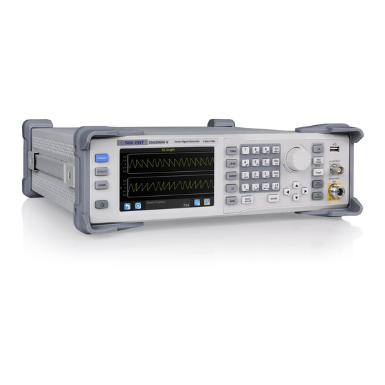
SIGLENT SSG5000X Overview The SIGLENT SSG5000X series is a bench top RF signal source, with an output frequency range from 9 kHz to 6 GHz. It features light weight, small size, and convenient interface make it ideal for R&D, education, production, and maintenance. - Page 16 SIGLENT modulation signals, support data source playback generated by MATLAB Support the playback of protocol files and can generate 5G_NR, LTE, WLAN, WCDMA, GSM, BLUETOOTH and other communication protocol signals Support the generation and playback of waveform sequence ...
-
Page 17: Table Of Contents
SIGLENT Contents Guaranty and Declaration ........................II General Safety Summary ........................III Safety Terms and Symbols ........................V SSG5000X Overview ..........................VIII Chapter 1 Quick Start ........................... 1 Appearance size ......................... 2 Preparing for Use ....................... 3 1.2.1 Adjust the Supporting Legs ..................3 1.2.2... - Page 18 SIGLENT 2.1.1 RF output Frequency ....................23 2.1.2 Freq Offset ........................ 24 2.1.3 Phase Offset ......................26 Level Setting ........................28 2.2.1 Level setting ......................29 2.2.2 Level Offset ....................... 30 2.2.3 ALC State ........................31 2.2.4 Flatness ........................32 Sweep Setting ........................
- Page 19 SIGLENT LF Setting ........................... 68 2.5.1 LF Source ........................68 2.5.2 LF Sweep ........................69 Utility ........................... 73 2.6.1 System ........................73 2.6.2 Store/Recall ....................... 84 Power Sensor ........................87 2.7.1 Power meter setting ....................87 2.7.2 Level Control ......................92 I/Q Modulation ........................
- Page 20 SIGLENT Chapter 3 Application Examples ....................156 Output RF signal ......................156 Correcting Line Loss...................... 157 Output a modulated signal ..................158 Output a pulse train ...................... 160 Output IQ modulated signal in Custom Mode ............162 Test OIP3 of Active Devices in Multitone Mode ........... 164 Play waveform sequence Using ARB Mode............
- Page 21 SIGLENT General Inspection ......................183 Troubleshooting ......................184 Chapter 6 Service and Support ..................... 189 Service Summary ......................189 Contact Us ........................190 SSG5000X User Manual XXI...
-
Page 23: Chapter 1 Quick Start
SIGLENT Chapter 1 Quick Start Subjects in this chapter: Appearance size Preparing for Use The Front Panel Rear Panel User interface Touch operation Parameter setting Help information SSG5000X User Manual 1... -
Page 24: Appearance Size
SIGLENT 1.1 Appearance size Figure 1-1 Front View Figure 1-2 Top View Figure 1-3 Side View SSG5000X User Manual 2... -
Page 25: Preparing For Use
SIGLENT 1.2 Preparing for Use 1.2.1 Adjust the Supporting Legs For benchtop operation, you may want to use the supporting legs. Adjust the supporting feet appropriately to tilt the RF signal source upwards. Figure 1-4 before adjusting Figure 1-5 after adjusting 1.2.2... -
Page 26: The Front Panel
SIGLENT 1.3 The Front Panel Figure 1-7 the Front Panel Table 1-1 Front Panel Description Description Description Function key USB Host LF output RF output Knob Direction key Digital keyboard Touch screen display area Power button SSG5000X User Manual 4... -
Page 27: Front Panel Function Keys
SIGLENT 1.3.1 Front Panel Function Keys Table 1-2 Function keys description Control Keys Description FREQ Set frequency, frequency offset, phase offset and other related parameters. LEVEL Set level, level offset, ALC state, flatness and other parameters, power sensor display and control functions. -
Page 28: Front Panel Key Backlight
SIGLENT RF ON/OFF RF signal output switch PRESET Press this button to revert to the default parameter. The default parameters refer to the default parameter table. UTILITY System and file related operations HOME You can get back to the main interface quickly 1.3.2... - Page 29 SIGLENT keyboard supports English uppercase and lowercase characters, numbers, and common symbols (including decimal points, blanks, spaces, and + /), mainly for editing the name of files or folders and setting parameters (refer to the "parameter setting" section). Figure 1-8 Digital keyboard Digit 0 and space bar switch.
- Page 30 SIGLENT When setting the amplitude, press this key to set the units as uV. When setting the frequency, press this key to set the units as MHz, if the input is a time-related parameter, press this key to set the unit as us.
-
Page 31: Front Panel Connectors
SIGLENT 1.3.4 Front Panel Connectors Figure 1-9 front panel connectors LF (low frequency) output Output the low frequency signal. This is a BNC connection .The output can also be configured to source the modulation waveform for FM and PM modulation types. -
Page 32: Rear Panel
SIGLENT 1.4 Rear Panel Figure 1-10 Rear Panel AC power input terminal The RF signal source can operate with AC power from specifications of the AC power supply supported by RF signal source are 100 V - 240 V at 45 Hz - 440 Hz. Please connect the RF signal source to the AC power supply with the supplied power cord. - Page 33 SIGLENT USB host The RF signal source can be used as the "main device" to connect to the external USB device. The interface reads the trace or state file from the U disk, or stores the current instrument state or trace to the U disk, and can also save the content displayed on the current screen in .BMP format to the U disk.
- Page 34 SIGLENT shows "Ext Ref". When an external reference is lost, exceeded, or disconnected, the instrument automatically switches to the internal reference, and the screen status bar will no longer display "Ext Ref". 10MHz OUT The [10MHz IN] and [10MHz OUT] connectors are commonly used to establish synchronization between multiple instruments.
- Page 35 SIGLENT SIGNAL VALID When the RF output frequency or amplitude is modified, the RF output connector of the front panel outputs the RF signal at the specified frequency and amplitude after a certain response and processing time in the internal circuit of the instrument. In this process, the...
- Page 36 SIGLENT Marker level = 0 V (negative polarity selected). 13. PATTERN_TRIG When the IQ Arb trigger source is "Ext", the connector is used to input the external trigger signal. 14. Q_OUT Output the analog, in–phase component of I/Q modulation from the internal baseband generator when the internal IQ modulation mode is on.
- Page 37 SIGLENT Used to input an external modulated I baseband signal when the external IQ modulation mode is on. 19. Q INPUT Use to input an external modulated Q baseband signal when the external IQ modulation mode is on. Note: [I INPUT] and [Q INPUT] connectors are only available on models equipped with IQ modulation.
-
Page 38: User Interface
SIGLENT 1.5 User interface Figure 1-11 User Interface Prompt status bar Display LOCAL (local) or REMOTE (remote). When REMOTE is displayed, the instrument is being controlled by a remote computer and the front panel input will be locked .To unlock the front panel (enter LOCAL mode), press Esc/Close to quit. - Page 39 SIGLENT AWGN: The status of the Additive White Gaussian Noise (AWGN) to a carrier when IQ Modulation. UF: Amplitude flatness function enabled. OFFSET: Amplitude offset enable. : The identification is displayed when a USB disk is inserted ...
- Page 40 SIGLENT RF: RF output state. Frequency, level or RF Sweep can be set. I/Q MOD: I/Q output state. IQ modulation can be set. UTILITY: System and file related parameters can be set. Power Sensor: Display the current reading of the power sensor after accessing the ...
-
Page 41: Touch Operation
SIGLENT 1.6 Touch operation The RF signal source provides a 5 inch capacitive touch screen to support various gesture operations. Including: Click on the screen parameters or menu to edit the parameters. Left or right slide switches menus. -
Page 42: Parameter Setting
SIGLENT 1.7 Parameter setting arameter input can be performed through touch screen, keypad and digital keys, knob or direction keys. This section introduces an example of three parameter setting methods by setting the center frequency to 100 MHz. Using the digital keyboard 1) Press FREQ;... -
Page 43: Help Information
SIGLENT 1.8 Help information The built-in help system of RF signal source provides help information for each function and menu option on the front panel. Press UTILITY button and select help. The center of the screen will pop up to help. -
Page 44: Chapter 2 Front Panel Operation
SIGLENT Chapter 2 Front Panel Operation This chapter describes in detail the function keys at the front panel and the associated functions. Subjects in this chapter: Frequency Setting Level Setting Sweep Setting Analog Modulation LF Setting ... -
Page 45: Frequency Setting
SIGLENT 2.1 Frequency Setting The value of the RF frequency is displayed in the header of the display (“Freq”). This field provides the direct input of the RF frequency. Alternatively, you can enter the RF frequency in the “Freq” dialog. -
Page 46: Freq Offset
SIGLENT Use the numeric keypad to input the desired value and press the unit button to select the desired unit. Optional units are GHz, MHz, kHz, and Hz. Press ENTER to select the current unit. Press ENTER or press the knob to enter the parameter editing state, and then use ... - Page 47 SIGLENT external mixer, by setting an offset; you can read the mixer signal’s frequency directly on the RF generator front panel. 1. Keypad operation Press FREQ->Freq Offset to make the focus fall on this parameter item. Use the numeric keypad to input the desired value and press the unit button to select ...
-
Page 48: Phase Offset
SIGLENT Note: The relationship between the RF output frequency, the display frequency and frequency offset is: Display frequency = RF output Frequency + Frequency offset The difference value between the display frequency and the frequency offset is the ... - Page 49 SIGLENT up and down direction keys, rotate the knob or press the numeric keypad to modify the value. Press ENTER, knob or ESC to exit the editing mode. 2. Touch screen operation Click on SHORTCUT->FREQ->Phase Offset to enter the interface of phase offset setting.
-
Page 50: Level Setting
SIGLENT 2.2 Level Setting The value of the RF level is displayed in the level text field located in the header of the display (labeled “Level”).This field provides the direct input of the RF level value .Alternatively, you can enter the level in the level dialog. -
Page 51: Level Setting
SIGLENT menu) Level setting 2.2.1 Setting the RF signal level Keypad operation: Press the LEVEL->Level to make the focus fall on this parameter item Use the numeric keypad to input the desired value and press the unit button to select ... -
Page 52: Level Offset
SIGLENT Long press edit box to enter the edit mode. Press the up and down direction keys, rotate the knob or press the numeric keypad to modify the value, and press the ENTER key, knob or ESC key to exit the edit mode. -
Page 53: Alc State
SIGLENT Touch operation Click on SHORTCUT->LEVEL->Level Offset to enter the interface of level offset setting. Click the level parameter, then pop up the keypad interface, then click the number symbol in the keypad to change the value. Click the check mark to confirm the modified value. -
Page 54: Flatness
SIGLENT Press LEVEL-> ALC State to expand the drop-down box, then rotate the knob or press the up and down direction keys to select ALC state. Touch operation Click on SHORTCUT->LEVEL->ALC state to select ALC state. ALC has three functions: "Off", "On" and "Auto”: ●... - Page 55 SIGLENT respective RF frequency. With frequencies which are not contained in the list, the level correction is determined by interpolation of the closest correction values. If there is only one point, it will not perform correction. The flatness correction function can adjust the RF output amplitude corresponding to the frequency point within the frequency range of the instrument to compensate for losses in the cable, or losses caused by other equipment.
- Page 56 SIGLENT Flatness settings Press LEVEL->Flatness, and then click the gear icon to enter the flatness list edit page. Table 2-1Flatness correction list Frequency correction(dB) Insert Press to insert a new row after the last row. Delete Press to delete the selected row.
- Page 57 SIGLENT Press to enter the set of flatness list filling. After entered into the set of flatness list filling, you can choose one of the following three methods to fill flatness list with power sensor. Flatness List In the flatness list edit page, insert the frequency list. Then enter the set of flatness list filling, choose “Flatness”...
- Page 58 SIGLENT state. Before or after “Fill Flatness with Sensor” executed, the RF state and sensor state will be turned on or turned off automatically. During filling the flatness list, the pop-up message will be shown as below. You should not remove the power sensor until the process is finished.
-
Page 59: Sweep Setting
SIGLENT 2.3 Sweep Setting When the RF sweep function is enabled, the RF signal is output from the N-type connector of [RF OUTPUT 50Ω] on the front panel. Note: The RF signal will be on only when the RF switch is on. -
Page 60: Step Sweep
SIGLENT progress bar. 2.3.2 Step Sweep The step sweep state is on by default. Click the slide to switch the on-off state. Click to enter the parameter setting menu of step sweep. Note: The step sweep and list sweep are mutually exclusive. One will shut off automatically when the other is on. -
Page 61: List Sweep
SIGLENT Note: Level sweep only support the line sweep mode. List Sweep 2.3.3 List sweep The list sweep state is off by default. Click the slide to switch the on-off state. Click the "more setting" to enter the table edit page of list sweep. -
Page 62: Direction
SIGLENT setting. Loading list: Click button to enter the file system directory. At this time, the sweep list file previously saved in the device can be selected to read, and the parameter can be modified. Save list: Click the button to enter the file system directory. At this time, enter the file name, then save the sweep list file. -
Page 63: Sweep Mode
SIGLENT from left to right. DOWN: The signal generator sweeps from the stop frequency or stop level to the start frequency or start level. The progress bar displayed in the parameter bar is swept from right to left. 2.3.5 Sweep Mode Default Sweep mode is “continuous”. -
Page 64: Point Trigger
SIGLENT Key: If the sweep mode is “continuous”, the device will start a one-time sweep after you press the Trigger button on the front panel or click Click to trigger button on the touch screen. If the sweep mode is “single”, first click the Execute single sweep button, then a one-time sweep will be started after you press the Trigger button on the front panel or click Click to trigger button on the touch screen. - Page 65 SIGLENT Click the drop-down box of point trigger mode to select the desired type: Auto: The default mode. If the sweep mode is “continuous”, just select one sweep type to start and sweep through each point continuously in one sweep cycle. If the sweep mode is “single”, first click Execute single sweep button to sweep through...
-
Page 66: Trigger Slope
SIGLENT start sweep one point when receiving a specified polarity TTL pulse. The sweep will stop when finish one sweep cycle. 2.3.8 Trigger Slope When the trigger mode or the point trigger mode is “Ext”, you can select “Positive” or “Negative”... - Page 67 SIGLENT conditions, and then press the Trigger key two times to meet the sweep cycle trigger and point trigger conditions to begin sweep. SSG5000X User Manual 45...
-
Page 68: Analog Modulation
SIGLENT 2.4 Analog Modulation 2.4.1 Amplitude Modulation (AM) Amplitude Modulation (AM) is a technique for delivering information by linearly varying the amplitude of an RF carrier signal. AM source can be selected as an internal source, external source or internal source + external source. - Page 69 SIGLENT level to the modulation depth is 50%/V 2.4.1.1 AM State Select MOD->AM-> AM State, and then turn on or off the level modulation. 2.4.1.2 AM Source An internal and/or external source can be selected for amplitude modulation. Press MOD->AM->AM Source to set “Int” or “Ext” or “Int + Ext”. The default is “Int”.
- Page 70 SIGLENT Int + Ext Use both the internal and externally applied modulation signals, this technique can be used to source dual tone AM. 2.4.1.3 AM Shape The SSG5000X supports modulation waveforms for internal “sine” and “square” modulation sources. Select MOD->AM-> AM Shape, after setting to “Int” or “Int+Ext”, you can select AM waveform as “Sine”...
-
Page 71: Frequency Modulation (Fm)
SIGLENT difference ΔP is satisfied: ΔP=6.02-20*log (m) When the “Ext” modulation source is selected, the sensitivity of the external modulation source level amplitude to the modulation depth is 50%/V. For example, the modulation depth is 100% when the external modulation signal is 2Vpp (offset is 0V), and the modulation depth is 50% when the external modulation signal is 1Vpp (offset is 0V). - Page 72 SIGLENT Enter the MOD interface via the MOD button and switch to the FM page. 2.4.2.1 FM State Select MOD ->FM->FM State, to turn FM on or off. 2.4.2.2 FM Source Select MOD ->FM-> FM Source to set “Int” or “Ext” or “Int + Ext”. The default is “Int”.
- Page 73 SIGLENT 2.4.2.3 FM Shape Select MOD->FM-> FM Shape. After setting to “Int” or “Int+Ext”, you can select FM waveform as “Sine” or “Square”. 2.4.2.4 FM Rate Select MOD->FM-> FM Rate, you can set the FM rate. The sine wave modulation frequency range is 0.01Hz~100kHz The square wave modulation frequency range is 0.01Hz~20kHz...
- Page 74 SIGLENT external modulation sensitivity. When the modulation source selects “Int+Ext”, the set value is the maximum value of the total offset, the internal source accounts for 50%, and the external source accounts for 50%. RF output offset = set value × 0.5 + external input signal amplitude × external modulation sensitivity.
-
Page 75: Phase Modulation (Pm)
SIGLENT 2.4.3 Phase Modulation (PM) Enter the PM interface Click the MOD icon in the main interface to enter the MOD interface. The MOD interface displays the PM page by default. You can switch to the PM modulation page by clicking or sliding left. - Page 76 SIGLENT 2.4.3.2 PM Source Select MOD ->PM->PM Source to set “Int” or “Ext” or “Int + Ext”. The default is “Int”. 1. Int Use the internal LF generator as the modulation signal source for PM. The PM Shape, PM deviation, and PM rate can be set.
- Page 77 SIGLENT 2.4.3.5 PM Deviation The setting range is . For the definition of N, refer to the data sheet. When the modulation source is set to “Int “, the set value is actually the frequency offset of the RF output.
-
Page 78: Pulse Modulation (Pulse)
SIGLENT signal, it only accounts for 50% of the maximum output offset. Note: The modulation function must be activated to modulate the output signal. You can turn it on or off by pressing the MOD ON/OFF button or you can open it by checking the MOD module on the home page, as shown in the figure: 2.4.4... - Page 79 SIGLENT 2.4.4.2 Pulse Out Select MOD->PULSE->Pulse Out to turn Pulse Out on or off. The default is off. On: Turn on the pulse output function. At this time, the signal source outputs the pulse signal generated by the internal pulse generator from the [PULSE IN/OUT] connector on the rear panel.
- Page 80 SIGLENT 2.4.4.4 Pulse Polarity The default is “Normal”. Click the drop down box to switch the pulse polarity type Normal: Perform pulse modulation when the pulse modulation signal is high. Inverse: Do not perform pulse modulation when the pulse modulation signal is high.
- Page 81 SIGLENT Train: Multiple pulse signals in one pulse period. At this time, the pulse sequence setting item appears, and the two settings “Double Pulse Delay” and “#2 Width” are hidden. Note: This setting item will be hidden when the modulation source is “Ext”.
- Page 82 SIGLENT of the first pulse of the single pulse modulated signal or the double pulse modulated signal can be set by touching screen keyboard or pressing the front panel keypad. Note: This setting item will be hidden when the modulation source is “Ext” or the pulse mode is “Train”.
- Page 83 SIGLENT 2.4.4.10 Trigger Out The default is “off”, Click the slide switch to switch the trigger output switch status. On: Turn on the trigger output function. At this time, the signal source outputs the trigger signal generated by the internal pulse generator from the [TRIG IN/OUT] connector on the rear panel.
- Page 84 SIGLENT modulation. At this time, the two settings “Trig Slope” and “Trig Polarity” are hidden. Ext Trig: The source receives the trigger signal from the [PULSE IN/OUT] connector on the rear panel. Each time a TTL pulse signal of the specified polarity is received, the source initiates a pulse modulation.
- Page 85 SIGLENT 2.4.4.13 Trigger Slope The default is “Positive”, click the drop-down box to switch the trigger slope. Positive: Trigger a pulse when the positive slope of the external trigger signal arrives. Negative: Trigger a pulse when the negative slope of the external trigger signal ...
- Page 86 SIGLENT 2.4.4.15 Pulse Train When the Pulse Mode is set to Train, the Pulse Train option appears. Click Pulse Train to enter the table edit page for the pulse sequence. As shown, the list edit page consists of the left action button, the middle table area, and...
- Page 87 SIGLENT Load list: Click the button to enter the file system directory. At this time, you can select and read the scan list file previously saved in the device, and you can edit and modify the next step. Save the list: Click the button to enter the file system directory.
- Page 88 SIGLENT As shown, the page consists of the upper drawing area and the lower control area: Plot area: A schematic diagram of the waveform generated from the data entered in the current pulse sequence table. The vertical direction represents the high and low level changes of each pulse signal in the pulse sequence, and the position of the high and low levels in the direction is unchanged;...
- Page 89 SIGLENT “Zoom In” and “Zoom Out” buttons are based on this position. It can be set by touching screen keyboard or pressing the front panel keypad to shift the current waveform to the corresponding position. The scaling operation for the drawing area can be achieved in the following ways: Zoom in, zoom out, restore and pan through the Control Area’s...
-
Page 90: Lf Setting
SIGLENT 2.5 LF Setting 2.5.1 LF Source The SSG5000X has an internal low-frequency signal generator that can be used as an internal source for low-frequency signal output or analog modulation. When output as a low-frequency signal, the LF output supports several common waveforms, and the frequency and amplitude of the low-frequency signal can be set. -
Page 91: Lf Sweep
SIGLENT 2.5.1.4 LF Offset Select LF-> LF Source->LF Offset to set the amplitude offset of the LF output. The setting range is. LFoffset LEVEL 2.5.1.5 LF Shape Select LF-> LF Source->LF Shape, you can select the LF output signal waveform. Current waveform types are “sine wave”, “square wave”, “Sawtooth wave”, “triangle wave”, and... - Page 92 SIGLENT 2.5.2.2 Start Freq Select LF->LF Sweep ->Start Freq to set the start frequency. 2.5.2.3 Stop Freq Select LF->LF Sweep ->Stop Freq to set the stop frequency. 2.5.2.4 Center Freq Select LF->LF Sweep->Center Freq to set the center frequency. 2.5.2.5 Freq Span Select LF->LF Sweep ->Freq Span to set the frequency Span.
- Page 93 SIGLENT 2.5.2.7 Sweep Times Select LF->LF Sweep ->Sweep Time to define the duration of the individual sweep steps. The “Dwell Time” set by the user is used as the step time of the sweep. 2.5.2.8 Trigger Mode Select LF->LF Sweep->Trigger Mode to select the LF frequency sweep mode. If you change the sweep mode during the execution, the signal generator stops the sweep and starts with the next trigger event at the initial value.
- Page 94 SIGLENT 1. Sawtooth The sweep runs from the start to the stop frequency. Each subsequent sweep starts at the start frequency that means the shape of the sweep sequence resembling a Sawtooth. 2. Triangle The sweep runs from start to stop frequency and back, that means the shape of the sweep resembles a triangle.
-
Page 95: Utility
SIGLENT 2.6 Utility 2.6.1 System 2.6.1.1 Setting Language Set the display language of SSG5000X. SSG5000X supports Chinese/English menus, help and interface display. Press UTILITY->Setting->Language to expand drop down list, and then select the desired language. Screen Saver Set the state of screen saver. When screen saver is switched on, screen saver will be enabled if no action is taken within the specified time. - Page 96 SIGLENT Press UTILITY->Setting ->Power On to expand drop down list, and then select “Default” or “Last”. Default: The factory defined default settings will be loaded at power on. For more details please refer to 错误!未找到引用源。. Last: The system setting before the last power-off will be loaded automatically at power-on.
- Page 97 SIGLENT factory defaults. To restore factory settings, in addition to loading the default settings, the following functions and parameters will also be configured. Table 2-2 Factory default Parameter Default Setting Language Chinese/English(depend factory config) Preset Type Default Beeper Screen Saver...
- Page 98 SIGLENT GPIB Address Level Flatness null Sweep List sweep Keep only one default scan point Mode Pulse Train Keep only one default pulse Reset & Clear Set “Reset & Clear” will restore the instrument configuration to factory settings, as well as clean up files stored by users in “Local”...
- Page 99 SIGLENT Off: If line power is available, you need to manually press the power key on the front panel to start the instrument. On: If line power is available, the instrument starts automatically. This is an idea feature for automatic or remote tests that may be difficult to physically reach.
- Page 100 SIGLENT change the time by inputting the value. 2.6.1.2 System Info Press UTILITY->System Info to view the instrument's system information, including: Startup Times Model Software Version Hardware Version Host ID Serial Number 2.6.1.3 Interface Press Utility ->Interface to view the instrument's remote control interface information,...
- Page 101 SIGLENT mask and gateway automatically according to the current network condition. When the DHCP state is off, the IP address, subnet mask and gateway will be configured by the user. IP Address Configure the network IP address. Press UTILITY->Interface ->IP Address, then move the cursor to specified location and press number keys to input value, finally press ENTER to make the setup effective.
- Page 102 “siglent”.) 3. GPIB Setting Set the GPIB address from 1 to 30. SSG5000X must use the SIGLENT USB-GPIB interface (optional) connected to the USB Host port located on the rear panel. Press UTILITY->Interface ->GPIB Address, and then press number keys to input value, finally press ENTER to make the setup effective.
- Page 103 SIGLENT 2. Key Test Press UTILITY->Self Test ->Key Test to enter the keyboard test interface. Press the function keys at the front panel one by one and observe whether the corresponding key is checked. If not, an error may have occurred in that key. To exit the test, press 8 three times or click the screen.
- Page 104 SIGLENT 2.6.1.5 Shutdown Press UTILITY->Shutdown to power off the instrument according to operating hints on the interface. 2.6.1.6 Preset Reset parameter settings according to the type of preset selected. Press UTILITY->Preset, to reset the parameters. 2.6.1.7 Update Press UTILITY->Update, and select the update file. Then click Recall to update the system software.
- Page 105 2.6.1.10 Contact Us Press UTILITY->Contact Us to view the contact information for SIGLENT. You can contact us to solve the problems meet in practical use. You can also write SSG5000X User Manual 83...
-
Page 106: Store/Recall
SIGLENT info@siglent.com or call your local SIGLENT sales office for support. 2.6.2 Store/Recall Press UTILITY->Store/Recall to enter file management page. Then you can select file by knob and fold or expand folders by left and right direction key. View Type Click View Type to change the type of files to show, including “All', “Data”, “State”... - Page 107 SIGLENT State file: .xml file: State saving file. Update file: .CFG file: Configuration update file; .ADS file: System update file. New Dir Click NewDir to create new folders. Press to switch the case of letter when entering the name of a new file.
- Page 108 SIGLENT Paste Click Paste to paste the copied file or folder to specified location. Recall Click Recall to load the selected file. Save Click Save to save the file with corresponding type according to the type of data. SSG5000X User Manual 86...
-
Page 109: Power Sensor
SIGLENT 2.7 Power Sensor The SSG5000X can be connected to a USB power sensor via the USB Host interface. First connect the USB power sensor to the USB Host connector on the rear panel. If the “Power sensor has been connected!” message pops up on the screen, the signal source has successfully activated the power meter control option, and you can always use the power sensor function. - Page 110 SIGLENT 2.7.1.1 Sensor Info Indicate the type of a connected power sensor. The sensor type is automatically detected. 2.7.1.2 Sensor State The default is “off”. Activate/deactivate level measurement by the power sensor. On: Turn on the power sensor measurement function, and the measurement control ...
- Page 111 SIGLENT 2.7.1.5 Statistics The default is “off”. When activated, statistics indicate the measured mean, maximum, minimum and the count of each measurement... On: Turn on the statistics function. Each statistical parameter is displayed on the parameter bar. Statistical parameters include average, minimum, maximum, and statistics.
- Page 112 SIGLENT measurement results. And the button name will change from “Click to perform zeroing” to “Zero In Progress...” After the zero adjustment is completed, the button name will be restored to the word “Click to perform zeroing”. Note: If the power meter does not have an internal or external zeroing option, the “internal”...
- Page 113 SIGLENT Off: The display is consistent with the actual reading of the power sensor. 2.7.1.9 Averaging Mode The default is “Auto”. Click the slide switch to switch the averaging mode. Auto: Automatically configure the average number of times based on the current ...
-
Page 114: Level Control
SIGLENT 2.7.2 Level Control As shown in the example, the sensor measures a proportional power in defined time intervals, derived from a coupler. It considers optionally the given S-parameters and returns the results to the generator. The signal generator compares the measured level with the set value and adjusts its output level accordingly. - Page 115 SIGLENT 2.7.2.1 Sensor State The default is “off”. Activate/deactivate level measurement by the power sensor. On: Turn on the power sensor level control function, and the measurement control refreshes the power sensor measurement value in real time. Off: Turn off the power sensor measurement function.
- Page 116 SIGLENT effect and the source will pop up a warning message. 2.7.2.5 Capture Range The capture range means that if the power sensor reading is within the effective capture range, it is a valid reading and the RF signal is adjusted and compensated. Set the capture range of the control system.
-
Page 117: I/Q Modulation
SIGLENT 2.8 I/Q Modulation I/Q modulation, i.e. two orthogonal signals (carriers with the same frequency, phase difference of 90°, generally expressed by Sin and Cos) and I (In-Phase, in-phase component) and Q (Quadrature Phase) signals are respectively modulated by carrier and transmitted together, thereby improving spectrum utilization. - Page 118 SIGLENT 1. Data Setup Select a data source type for modulation. Choices: PN7 | PN9 | PN15 | PN23 | User. Default: PN7. PN7 | PN9 | PN15 | PN23 When selecting “PN7 | PN9 | PN15 | PN23” as data source type, software generates data source bit automatically.
- Page 119 SIGLENT 2. Symbol Rate Set the symbol rate (symbols per second) of the waveform. Range: (1000/Oversampling) to (240000000/Oversampling) Symbols/second. Default: 1000000 Symbols/second. 3. Symbol Length Set the length of modulated symbols. Range: 100 to 100000. Default: 512. 4. Bits/Symbol Display the number of bits contained in one modulated symbol. It is read only, not settable.
- Page 120 SIGLENT Choices: 16QAM | 32QAM | 64QAM | 128QAM | 256QAM | 512QAM. Default: 16QAM. Select a type in ASK category for modulation. Choices: 2ASK | 4ASK | 8ASK | 16ASK. Default: 2ASK. Select a type in PSK category for modulation.
- Page 121 SIGLENT User When selecting “User” as modulation type, the “Custom” button appears for custom editing. constellation In the custom constellation editing window, you can insert or delete constellation points and edit the IQ data for each constellation point manually.
- Page 122 SIGLENT On the left side of the window, it shows the constellation display of current editing. Note: When editing the constellation points, the number of points must be a value of power of 2, otherwise there will be error message when you click “Update” button.
- Page 123 SIGLENT 2. Filter Alpha/BT Set the Alpha factor of the filter (BT of Gaussian filter). Range: 0.01~1. Default: 0.35. 3. Filter Length Set length of filter in symbols. Range: 1~512. Default: 128. 4. OverSampling Set the oversampling ratio of the waveform. The waveform Sample Rate is determined based on Symbol Rate and Oversampling ratio.
-
Page 124: Multitone
SIGLENT 2.8.1.5 Update Regenerate the waveform data based on the current settings. 2.8.1.6 Save Waveform to a “*.arb” file. Save the current settings 2.8.2 Multitone Press I/Q->Multitone to enter multitone mode. Multitone mode supports up to 20 tones. The highest sampling rate is 300 MHz, and the maximum spectral spacing can be up to 120MHz. - Page 125 SIGLENT center frequency. 2.8.2.3 Sample Rate Press I/Q->Multitone ->Sample Rate to set multitone sample rate. Support up to 300MHz sampling rate. 2.8.2.4 Freq Spacing to set frequency spacing. The frequency spacing here Press I/Q->Multitone->Freq Spacing refers to the frequency spacing from the leftmost spectrum to the rightmost spectrum.
-
Page 126: Arb
SIGLENT 2.8.2.7 Load State Press I/Q->Multitone->Load State to load the ‘.mulstate’ file from the hard disk as the current setting parameters. 2.8.3 2.8.3.1 ARB State ->ARB->ARB State to turn ARB on or off. Press I/Q 2.8.3.2 Select Waveform Select Waveform Press I/Q->... - Page 127 SIGLENT 2.8.3.3 Waveform Segment Waveform Segment Press I/Q-> -> , to enter the volatile waveform file directory, Waveform segment must reside in volatile storage media before they can be played, edited, or included in a sequence. 1. Load Load the waveform segment file (*.arb) from the non-volatile memory into the volatile memory,...
- Page 128 SIGLENT Select Waveform waveform segment in 4. Rename Rename the selected waveform segment. 5. Clear Clear the files in the waveform segment. 2.8.3.4 Waveform Sequence Waveform Sequence Press I/Q -> -> ,to enter the waveform sequence directory, and the current page displays the list of existing waveform sequences.
- Page 129 SIGLENT However the repetition of a nested sequence counts as additional segments. For example, if a waveform sequence contains 24 segments and one nested sequence with 10 segments, the nested sequence can only repeat (1024-24) / 10 = 100 times at most.
- Page 130 SIGLENT Build Press to create a sequence. All operations of creating a waveform sequence can be realized through the touch screen of the signal generator: On the left side, click to add the segment or sequence to the new sequence;...
- Page 131 SIGLENT 2.8.3.4.3 Playing a Sequence After creating a sequence, we can select the sequence to play: Select Waveform 1) Press I/Q -> -> , and select a waveform sequence. ARB State 2) Set to on. 3) Turn on the I/Q MOD module switch on the main page, or set MOD ON/OFF to on.
- Page 132 SIGLENT 2.8.3.5.2 Modulation Atten Users can adjust the amplitude of I and Q signals before entering the IQ modulator. When the modulator attenuation type is set to manual, the waveform generator can set the appropriate modulator attenuation value to obtain the best ACPR characteristics.
- Page 133 SIGLENT Carrier + Noise: both the noise and the carrier are output from the internal baseband generator. Carrier: only the Carrier is output from the internal baseband generator. Noise: only the addictive noise is output from the internal baseband generator.
- Page 134 SIGLENT values. 3. Carrier to Noise Ratio Format This feature allows the AWGN C/N to be set using the Eb/No (energy per bit over noise power density at the receiver or signal to noise ratio per bit) form. Eb/No Carrier Bit Equation: 4.
- Page 135 SIGLENT This filter is applied as the ARB waveform plays, rather than in the waveform data itself. 2.8.3.5.5 Baseband offset A frequency offset can be set for the baseband spectrum, and the range is 60 MHz. Common uses for the offset include: offset the carrier from any LO feedthrough (carrier signal spur at the carrier frequency) ...
- Page 136 SIGLENT from different digital standards can be created by this function. Because the multi carrier files are processed by the ARB generator, the composed waveform file must be created before it is loaded to and played by the ARB. The SSG5000X stores the created multi carrier waveform file under user definable name;...
- Page 137 SIGLENT 2.8.3.6.3 Power Reference Defines the way the individual carriers in a composed multi carrier signal are leveled. Peak: The individual carriers are leveled based on their peak power and the configured Carrier Gain. For example a multi carrier signal is composed of two waveform files, First carrier "Gain"...
- Page 138 SIGLENT This page comprises the settings of each carrier, and all the carriers are displayed in table form. The number of rows corresponds to the number of carriers. Each row of parameters in the table represents the settings of a single carrier:...
- Page 139 SIGLENT the carrier list. Assistant: Enter the assistant setting menu of carrier list, which is used to generate a list of carriers with fixed carrier signal and equal frequency spacing. The menu contains the following settings: Select Waveform: Set the carrier signal applied in the carrier list by selecting the ...
- Page 140 SIGLENT resulting period is always calculated for all carriers in the carrier table. Use the "Carrier Table > Info" function to obtain information on the sample rate and file length data of each carrier. Longest File Wins: The longest I/Q file in the carrier table defines the resulting signal ...
- Page 141 SIGLENT waveform setting in the carrier table. 2.8.3.6.8 Create and Load Click this item, the current multicarrier will be created and loaded into the volatile memory according to the set waveform name, and the multicarrier will be played automatically. 2.8.3.6.9...
- Page 142 SIGLENT Press I/Q->ARB->Marker Utilities to enter marker setting menu. 2.8.3.7.1 About the Waveform Marker SSG5000X provides four waveform markers to mark specific points on a waveform segment. You can set each marker’s polarity and marked points (on a single sample point or over a range of sample points).
- Page 143 SIGLENT rear panel will output the corresponding pulse signal according to the currently selected marker and related settings. 2.8.3.7.4 Marker Polarity The default value is "Negative". Click the drop-down box to switch the polarity of the marker. Positive: the high level (3.3V) signal is output during the on marker points, and the ...
- Page 144 SIGLENT RF Signal Marker Segment Marker Polarity = Positive When marker polarity is positive, the RF output is blanked during the marker points. RF Signal Marker on Segment Marker Polarity = Negative When marker polarity is negative, the RF output is blanked during the marker points.
- Page 145 SIGLENT The delay range is -4000 ns to 860 us, and default value is 0 us. 2.8.3.7.7 Set Markers Click this item to enter the marker setting interface. As shown in above figure, the marker setting page is composed of waveform segment selection area, marker setting area and menu bar.
- Page 146 SIGLENT In the marker setting area, each row of parameters in the table represents the marker settings of a segment: First Mkr Point: Set the sample point corresponding to the first marker point of the segment. Last Mkr Point: Set the sample point corresponding to the last marker point of the ...
- Page 147 SIGLENT Clear: Clear all the marker points from a waveform segment. Apply: Make the current marker points setting of a segment effective. Display: Click to view the marker signal diagram. Return: Return to the previous menu. ...
- Page 148 SIGLENT power level of the output signal. Control area: Click the button to return to the previous marker point setting page; Click the button to resume the diagram to the initial state; Click the button to zoom in the diagram;...
- Page 149 SIGLENT 2.8.3.8 Waveform Utilities Press I/Q->ARB->Waveform Utilities to enter the waveform utilities setting menu. 2.8.3.8.1 Select Segment Select the waveform segment for scaling or peak clipping the I and Q data. 2.8.3.8.2 Scaling Set the amplitude scaling percentage of a waveform segment.
- Page 150 SIGLENT 2.8.3.8.3 Clipping Type Set the waveform clipping type to circular or rectangular clipping. The clipping function enables you to reduce peak–to–average power, and consequently spectral regrowth, by clipping the waveform. Clipping limits waveform power peaks by clipping the I and Q data to a selected percentage of its highest peak.
- Page 151 SIGLENT 2.8.3.8.4 Clip |I+jQ| to Set the percentage of I / Q signal value (√ ) reduced to the peak value. 2.8.3.8.5 Clip |I| to Set I Waveform clipping percentage. 2.8.3.8.6 Clip |Q| to Set Q Waveform clipping percentage. SSG5000X User Manual 129...
- Page 152 SIGLENT 2.8.3.8.7 Apply to Waveform Click the "Apply to Waveform" button to make waveform scaling or clipping effective. Note: Waveform scaling and clipping are non–reversible. Any data lost in the scaling or clipping operation cannot be restored. Save a copy of the waveform file before scaling or clipping.
- Page 153 SIGLENT Generate a CCDF waveform diagram based on the selected waveform. The vertical direction represents probability; The horizontal direction represents a multiple of the relative average power (in dB). The the grey curve is yellow curve is the current CCDF curve of the selected waveform. And the CCDF reference curve.
- Page 154 SIGLENT 2.8.3.9.1 Trigger Type Trigger type defines the trigger mode: how the waveform plays when triggered, and you can set the trigger type to continuous, single, segment advance or ext gated. 1) Continuous: Continuous mode repeats the waveform until you turn the signal off or select a different waveform, trigger mode, or response (Free Run, Trigger &...
- Page 155 SIGLENT 3) Reset & Run: Plays the waveform when a trigger is received; subsequent triggers restart the waveform. 2.8.3.9.3 Single Mode The single mode can be set to no retrigger, buffered trigger or restart on trigger mode. 1) No Retrigger: Ignores an early trigger received while a waveform is playing.
- Page 156 SIGLENT 2) Continuous: A segment in a sequence plays continuously until the waveform receives another trigger. If a trigger is received while a segment is playing, the segment plays to completion. The dual ARB player then advances to the next segment and plays that segment continuously.
- Page 157 SIGLENT 2.8.3.9.7 Ext Polarity The Ext Polarity can be set to positive or negative. Positive: The signal generator responds during the trigger signal low state. Negative: The signal generator responds during the trigger signal high state. Note: In Continuous, Single, and Segment Advance modes, use the “Ext Polarity” item to set the external trigger polarity.
- Page 158 SIGLENT 2.8.3.9.10 Delay Samples Set the number of sampling points from the time when the external trigger signal is received until the trigger takes effect, that is delay time = delay samples / sample clock. Note: When the trigger mode is initially selected or when changing from one trigger mode to another, the carrier signal on the RF output may be lost until the modulating signal is triggered.
- Page 159 SIGLENT waveform segment. When the waveform sequence is played, the waveform segment header files are ignored and the waveform sequence header file is automatically loaded into the signal generator. 2.8.3.10.2 Editing a Waveform Header The editing interface of a waveform header is shown as below.
- Page 160 SIGLENT Parameter Display Area There are three columns parameters in parameter display area. Header Field: list all the file header parameters. Saved Header Settings: show the header settings saved in the currently selected waveform segment or sequence header file. “Unspecified” means that there is no setting saved for that particular parameter.
- Page 161 SIGLENT 2.8.3.11 Waveform File Type ARB waveform segments can be loaded into three file types: * .arb, * .WDbin and * .txt, which can be copied to the device's non-volatile memory through ftp or U disk. 2.8.3.11.1 arb file The arb file (* .arb) is generated by the signal generator, or generated by the EasyIQ software.
- Page 162 SIGLENT the file in the form of floating point numbers. I and Q are stored in two columns, I in the first column and Q in the second column. SSG5000X User Manual 140...
-
Page 163: Awgn
SIGLENT 2.8.4 AWGN Press I/Q->AWGN to enter the AWGN setting menu. You can use AWGN ( Additive White ) to modulate the Carrier waveform. Gaussian Noise Use the following steps to apply 10 MHz bandwidth noise to a 1 GHz, 0 dBm carrier. - Page 164 SIGLENT 2.8.5.1 I/Q Mod State Turn on or off the I/Q modulation. When turn on the Custom, Multitone, ARB or AWGN state, the I/Q Mod State will be automatically turned on. 2.8.5.2 I/Q Source Set the I/Q modulation source to internal or external.
- Page 165 SIGLENT c. Turn the RF output on. 2.8.5.3 Compensation Channel Set the compensation channel as RF or Output. RF:Compensate RF channel of the front panel. Output:Compensate the I/Q signal output from the rear panel connectors. 2.8.5.4 I/Q Adjustment Use the I/Q Adjustments to compensate for or add impairments to the I/Q signal.
- Page 166 SIGLENT Offset the phase of the Q signal relative to the phase of the I signal. The baseband quadrature adjustment key is calibrated in units of degrees. This can optimize the image leakage. 2.8.5.5 I/Q Output This adjustment is only applied to the I and Q signal on the rear panel output.
- Page 167 SIGLENT I/Q Common Offset Adjust the DC offset of both I and Q signals simultaneously. 2.8.5.6 I/Q Swap Turning on the I/Q Swap state, the analog I and Q signals output from the rear panel are interchanged, and the I and Q signals modulating the carrier are interchanged.
-
Page 168: Shortcut Keys
SIGLENT 2.9 Shortcut Keys 2.9.1 PRESET Recall the preset setting and restore the signal generator to a specified status. Press UTILITY->Setting ->Preset Type to select “Default” or “User”. Press PRESET to load the factory settings listed in the following table or User-defined ... - Page 169 SIGLENT Sweep State Sweep Mode Continuous Direction Trigger Mode Auto Point Trigger Auto Trigger Slope Positive Step Sweep Step Sweep State Start Freq 6 GHz Stop Freq 6 GHz Start Level -130dBm Stop Level -130dBm Sweep Points Dwell Time 30 ms...
- Page 170 SIGLENT AM State AM Source AM Shape Sine AM Rate 1 kHz AM Depth 50 % FM State FM Source FM Shape Sine FM Deviation 100 kHz FM Rate 10 kHz PM State PM Source PM Shape Sine PM Rate...
- Page 171 SIGLENT Pulse Period 10 ms Pulse Width 2 ms Double Pulse Delay 4 ms #2 Width 2 ms Trigger Out Pulse Trigger Auto Trig Delay 140 ns Trig Slop Positive Pulse Polarity Normal Pulse Out Trig Polarity Normal Pulse Train...
- Page 172 SIGLENT Start Freq 500 Hz Stop Freq 1.5 kHz Center Freq 1 kHz Freq Span 1 kHz Sweep Time Trigger Mode Auto Sweep Shape Sawtooth Trigger Mode Linear Direction IQ MOD IQ MOD State Custom Custom State Data Setup Symbol Rate...
- Page 173 SIGLENT Filter Length Oversampling Multitone Multitone State Tone Number Single Side Sample Rate 2 MHz Freq Spacing 1 MHz ARB State Select Waveform *NONE ARB Setup Sample Clock 2 MHz Modulator Atten Type Auto Modulation Atten 6 dB Real Time AWGN...
- Page 174 SIGLENT Carrier Bandwidth 1 Hz Flat Noise Bandwidth 1 Hz Filter Type None Baseband Offset Multi Carrier Waveform Name MULTICARRIER Power Reference Peak Carrier Table SINE_WAVE,0,0,0 Signal Period Mode Signal Period 100 us Sampling Rate 2 MHz Marker Utilities Marker Number...
- Page 175 SIGLENT Clipping Type |I+jQ| Clip |I+jQ| to 100 % Trigger Trigger Type Continuous Continuous Mode Free Run AWGN AWGN State Bandwidth 10 MHz I/Q Control I/Q Mod State I/Q Source Internal Compensation Channel I/Q Adjustment Gain Balance 0 dB I Offset...
-
Page 176: Home
SIGLENT I Output Offset 0 mV Q Output Offset 0 mV I/Q Common Offset 0 mV 2.9.2 Home Return to the home page. 2.9.3 Trigger When the trigger mode of the sweep is Key, press this key once to trigger a sweep. -
Page 177: Mod On/Off
SIGLENT 2.9.5 MOD ON/OFF Enable/disable modulation on the RF output. When enabled, the backlight will light, the screen status bar MOD will change from gray to blue, and RF output modulation will be activated. Press this button again to disable modulation. When disabled, the backlight is off, all modulation is off, and the user interface status bar MOD changes from blue to gray. - Page 178 SIGLENT Chapter 3 Application Examples 3.1 Output RF signal Output a RF signal with a frequency of 3GHz and amplitude of 0dBm from the [RF OUTPUT 50Ω] connector. Restore factory settings Press UTILITY or the touch screen to set UTILITY -> Setting -> Preset Type->...
- Page 179 SIGLENT Turn on RF output Press RF ON/OFF or press the HOME key back to the main interface, select the RF block, the white square on the left of ON to enable RF output. When enabled, the RF ON/OFF key backlight turns green and the RF state in the status bar changes to blue.
- Page 180 SIGLENT Set the Frequency & Level Press FREQ, and enter the 1GHz with the numeric keypad, or click the frequency on the touch screen to pop up the keypad to input 1GHz. Press LEVEL, and enter the 0dBm with the numeric keypad, or click the amplitude on the touch screen to pop up the keypad to input 0dBm on the keypad.
- Page 181 SIGLENT Restore factory settings Press UTILITY or the touch screen to set System -> Setting -> Preset Type-> Default. Press PRESET or reset the system settings to perform reset operations. Set the carrier frequency & amplitude Press FREQ and enter 1GHz with the numeric keypad, or click the frequency input box on the touch screen to pop up the keypad to input 1GHz on the keypad.
- Page 182 SIGLENT Press MOD ON/OFF and then press RF ON/OFF. The backlights of MOD ON/OFF and RF ON/OFF will be illuminated. RF and MOD labels in the status bar will change from gray to blue. At this time, the signal on the [RF OUTPUT 50Ω] connector will match the settings configured above.
- Page 183 SIGLENT Install the pulse train option Activate the pulse train generator option. Edit pulse list Press MOD or select ANALOG MOD from the Home page. You can swipe left or right or press MOD repeatedly to reach the Pulse Mode screen. Set Pulse Mode to Train, and the Pulse Train menu will appear.
- Page 184 SIGLENT Enable the RF modulation output Press MOD ON/OFF and then press RF ON/OFF. The backlights of MOD ON/OFF and RF ON/OFF will be illuminated. RF and MOD labels in the status bar will change from gray to blue. At this time, the signal on the [RF OUTPUT 50Ω] connector will match the settings as configured above.
- Page 185 SIGLENT 1MHz, and Symbol Length to 512; Open the Modulation setting interface, and set Mod Type to QAM, QAM Type to 32QAM; Open the Filter setting interface, and set Filter Type to RootCosine, Filter Alpha to 0.35, Filter Length to 128, OverSampling to 2;...
- Page 186 SIGLENT 3.6 Test OIP3 of Active Devices in Multitone Mode OIP3 is a key indicator for evaluating the linearity of active devices. This can be tested using the SSG5000X. The following steps describe how to generate a two-tone continuous wave signal with a carrier frequency of 3.2 GHz and an interval frequency of 1 MHz to test OIP3 of the active...
- Page 187 SIGLENT Set the baseband signal Press I/Q or select IQ MOD block from the Home page, and then click Multitone. Set Tone Number to 1; Set Sample Rate to 10 MHz; Set Freq Spacing to 1 MHz; Set Single Side state off;...
- Page 188 SIGLENT MHz. The signal is used as the input of the active device, and the output signal is tested to obtain the OIP3 characteristic as shown in the following figure. Note: IQ compensation can be performed through I/Q Control->I/Q Adjustment menu of the SSG.
- Page 189 SIGLENT Press UTILITY or touch Preset Type-> Default. Press PRESET or reset the system settings to perform the reset operation. Create Waveform Sequence Press I/Q -> ARB -> Waveform Sequence, and then click “Build” button to enter the creating new waveform sequence interface;...
- Page 190 SIGLENT 3.8 Add AWGN to Modulated Signal Using ARB Mode Using the SSG5000X's ARB (arbitrary waveform) mode, you can add Additive White Gaussian Noise (AWGN) to the carrier while modulating the carrier. Restore factory settings Press UTILITY or the touch screen to set System -> Setting -> Preset Type->...
- Page 191 SIGLENT Press FREQ and enter 2GHz with the numeric keypad, or click the frequency input box on the touch screen to pop up the keypad to input 2GHz on the keypad. Set the real-time AWGN function Press I/Q-> ARB-> ARB Setup-> Real Time AWGN to enter real-time AWGN setting interface;...
- Page 192 SIGLENT analyzer, set the center frequency to 2 GHz, turn on the trace averaging function, and the spectrum of the modulated wave with Additive White Gaussian Noise is shown below. SSG5000X User Manual 170...
- Page 193 SIGLENT Chapter 4 Programming Overview The SSG5000X Signal Generator features a LAN, USB Device, and SIGLENT GPIB—USB module interfaces. By using a computer with these interfaces, and a suitable programming language (Python, C+, .NET, etc., and NI-VISA software), users can remotely control the signal generator using standard SCPI (Standard Commands for Programmable Instruments) commands.
- Page 194 SIGLENT For standard installations, you can use NI-VISA on your PC for the VXI driver. If you wish to control the instrument without NI-VISA, use sockets or telnet. Connect the SSG USB Device port to a PC with a USB A-B cable.
- Page 195 GPIB: Connecting via the USB-Host port Refer to the following steps to finish the connection via USB: Install NI-VISA on your PC for GPIB driver. Connect the SSG USB Host port to a PC’s GPIB card port, with SIGLENT USB-GPIB adaptor. Switch on the SSG...
- Page 196 SIGLENT Figure 4-4SIGLENT USB-GPIB Adaptor Press button on the front panel System→Interface→GPIB to enter the GPIB number. The SSG will be detected automatically as a new GPIB point. SSG5000X User Manual 174...
- Page 197 SIGLENT 4.2 Build Communications 4.2.1 Build Communications Using VISA NI-VISA includes a Run-Time Engine version and a Full version. The Run-Time Engine version provides NI device drivers such as USB-TMC, VXI, GPIB, etc. The full version includes the Run-Time Engine and a software tool named NI MAX that provides a user interface to control the device.
- Page 198 SIGLENT The NI-VISA installing dialog is shown above. Click Next to start the installation process. Set the install path, default path is “C:\Program Files\National Instruments\”, you can change it. Click Next, dialog shown as above. Click Next twice, in the License Agreement dialog, select the “I accept the above 2 License Agreement(s).”, and click Next, dialog shown as below:...
- Page 199 SIGLENT Click Next to run installation. Now the installation is complete, reboot your PC. 4.2.2 Build Communications Using Sockets/Telnet Through the LAN interface, VXI-11, Sockets and Telnet protocols can be used to communicate with the SSG. VXI-11 is provided in NI-VISA, while Sockets and Telnet are commonly included in the operating system (OS) of many computers.
- Page 200 SIGLENT fundamental technology used for computer networking and allows applications to communicate using standard mechanisms built into network hardware and operating systems. The method accesses a port on the signal generator from which bidirectional communication with a network computer can be established.
- Page 201 SIGLENT 4.3 Remote Control Capabilities 4.3.1 User-defined Programming Users can use SCPI commands to program and control the signal generator. For details, refer to the introductions in “Programming Guide”. 4.3.2 Send SCPI Commands via NI MAX Users can control the signal generator remotely by sending SCPI commands via NI-MAX software.
- Page 202 SIGLENT view the operation information. Note: The “*IDN?” command (known as the Identification Query) returns the instrument manufacturer, instrument model, serial number, and other identification information. 4.3.2.2 Using LAN Select “Add Network Device”, and select “VISA TCP/IP Resource” as shown: Run NI MAX software.
- Page 203 SIGLENT shown. Click Finish to establish the connection: After a brief scan, the connection should be shown under Network Devices: SSG5000X User Manual 181...
- Page 204 SIGLENT Click “Open VISA Test Panel” option button, then the following interface will appear: Click “Input/Output” option button and click “Query” option button. If everything is OK, you will see the Read operation information returned as shown below. 4.3.1 Web Control With the new embedded web server, users can control the SSG through LAN from a web browser on PC or mobile terminals.
-
Page 205: General Inspection
The consigner or carrier will be responsible for damages to the instrument resulting from shipment. SIGLENT will not provide free maintenance or replacement. Inspect the instrument If the instrument is found to be damaged, defective or fails in electrical or mechanical tests, please contact SIGLENT. -
Page 206: Troubleshooting
SIGLENT 5.2 Troubleshooting Before calling SIGLENT, or returning an SSG for service, perform the quick checks listed below. This check may eliminate the problem. If the problem remains still, please contact SIGLENT and provide your device information of the SSG (Get method: UTILITY->System Info). - Page 207 SIGLENT keyboard is broken. Do not disassemble the instrument by yourself and contact SIGLENT. 3. Correct setting but incorrect waveform output (1)No RF output -Check that the signal cable is securely connected to the corresponding [RF OUTPUT 50 Ω] port.
- Page 208 SIGLENT -If an external modulation source is used, make sure that the external source is connected correctly and has an output and should work within the range established by the source. 4. Sweep is abnormal: (1)Scanning stagnation The user interface frequency zone/amplitude zone displays a scan progress bar indicating that a scan operation is in progress.
- Page 209 SIGLENT -If the current scan type is set to Frequency, the amplitude value does not change. 5. USB device cannot be recognized: (1) Check if the USB device is connected to other instruments or the computer can work normally. (2) Confirm the flash type U disk device used. This instrument does not support the hard disk type U disk device.
- Page 210 SIGLENT (6) Check if all connections are tightened. 7. Pop-up Message: The instrument may display prompt messages, error messages or state messages according to the current working status. These messages are displayed to help you to use the instrument correctly and are not instrument failures.
-
Page 211: Chapter 6 Service And Support
(accessories for a period of one year) from the date of shipment from an authorized Siglent distributor. If the product proves defective within the respective period, SIGLENT will provide repair or replacement as described in the complete warranty statement. -
Page 212: Contact Us
SIGLENT 6.2 Contact Us China: SIGLENT TECHNOLOGIES CO., LTD. Add: Bldg. No.4 & No.5, Antongda Industrial Zone, 3rd Liuxian Road, Bao'an District, Shenzhen, 518101, China. Tel: + 86 755 3661 7876 Fax: + 86 755 3359 1582 Email: sales@siglent.com; Website: http://www.siglent.com/ens/ USA: SIGLENT Technologies America, Inc. - Page 213 SIGLENT SIGLENT TECHNOLOGIES EUROPE GmbH ADD: Liebigstrasse 2-20, Gebaeude 14, 22113 Hamburg Germany Tel: +49(0)-819-95946 Fax: +49(0)-819-95947 Email: info-eu@siglent.com Website: www.siglenteu.com SSG5000X User Manual 191...
Need help?
Do you have a question about the SSG5000X Series and is the answer not in the manual?
Questions and answers