SIGLENT SDG800 Series User Manual
Function/arbitrary waveform generator
Hide thumbs
Also See for SDG800 Series:
- Quick start manual (16 pages) ,
- Programming manual (83 pages) ,
- Service manual (57 pages)

Related Manuals for SIGLENT SDG800 Series


Summary of Contents for SIGLENT SDG800 Series
-
Page 1: User Manual
User Manual SDG800 Series Function/Arbitrary Waveform Generator UM02008-E02B 2014 SIGLENT TECHNOLOGIES CO., LTD... - Page 2 Declaration Copyright © SIGLENT TECHNOLOGIES CO., LTD. All rights reserved. Contents in this Manual are not allowed to be copied, extracted and translated before being allowed by SIGLENT Company SDG800 User Manual...
- Page 3 Do not operate with suspected failures. If you suspect there is damage with this product, you should have it inspected by qualified service personnel authorized by SIGLENT before further operations. SDG800 User Manual...
- Page 4 Provide proper ventilation. Do not operate in wet/damp conditions. Do not operate in an explosive atmosphere. Keep the product’s surfaces clean and dry. Not position the equipment so that it is difficult to operate the disconnecting device (detachable plug) SDG800 User Manual...
- Page 5 If the equipment is used in a manner not specified by the manufacturer, the protection provided by the equipment may be impaired. This product has been tested to the requirements of CAN/CSA-C22.2 No. 61010-1, second edition, including Amendment 1, or a later version of the same standard incorporating the same level of testing requirements.
- Page 6 Safety Terms and Symbols Terms in this guide, these terms may appear in this manual: Terms on the product, terms below may appear on the product: DANGER: Indicates an injury or hazard that may immediately happen. WARNING: Indicates an injury or hazard that may not immediately happen. CAUTION: Indicates that a potential damage to the instrument or other property might occur.
-
Page 7: Introduction Of Sdg800 Series
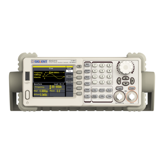
Introduction of SDG800 Series The manual covers the following three types of SDG800 Series Function/Arbitrary Waveform Generators: SDG830,SDG810, SDG805. SDG800 Series Function/Arbitrary Waveform Generators adopt the direct digital synthesis (DDS) technology, which can provide stable, high-precision, pure and low distortion signals. Its combination of excellent system features, easiness in usage and versatile functions makes this generator a perfect solution for your job now and in the future. - Page 8 DDS technology provides precise, stable and low distortional output signal. 3.5’TFT color LCD display. 125MSa/s sampling rate, 14-bit resolution. Frequency characteristics: Sine: 1μHz to 30MHz Square: 1μHz to 10 MHz Ramp: 1μHz to 300kHz Pulse: 500μHz to 5MHz White Noise: 10MHz bandwidth (-3dB) Arbitrary: 1μHz to 5MHz ...
-
Page 9: Table Of Contents
Catalogue General Safety Summary ................. II Introduction of SDG800 Series ..............VI 1. Getting Started ................... 1 1.1. General Inspection ................2 1.2. Handle Adjustment ................3 1.3. The Front/Rear Panel ............... 4 1.4. To Set a Waveform ................7 1.5. - Page 10 General Inspecting ................113 Troubleshooting ..................114 5. Service and Support ................115 Maintain summary................. 115 Contact SIGLENT ................. 116 6. Appendix ....................117 Appendix A: Accessories ............... 117 Appendix B: Daily Maintain and Cleaning ..........118 SDG800 User Manual...
-
Page 11: Getting Started
1. Getting Started This chapter covers the following topics: General Inspection Handle Adjustment The Front/Rear Panel To Set a Waveform To Set Modulate/Sweep/Burst To Set Output To Use Digital Input To Use Store/Utility/Help Function SDG800 User Manual... -
Page 12: General Inspection
1.1. General Inspection When you get a new SDG800 Series Function/Arbitrary Waveform Generator, you are suggested to take the following steps to inspect the instrument. 1. Inspect the shipping container for damage. If there are damages in the packing or foam, keep them until the whole machine and the accessories pass the electric and mechanical testing. -
Page 13: Handle Adjustment
1.2. Handle Adjustment To adjust the handle position of SDG800 Function/Arbitrary Waveform Generator, please grip the handle by the sides and pull it outward. Then, make the handle rotate to the desired position. Figure 1- 1 Viewing Position and Carrying Position SDG800 User Manual... -
Page 14: The Front/Rear Panel
1.3. The Front/Rear Panel When you get a new SDG800 Series Function/Arbitrary Waveform Generator, first you need to understand how to operate the front/rear panel correctly. This chapter will make a brief introduction and description for the operation and functions of the front/rear panel. - Page 15 Waveform Number USB Host Knob keys keys Menu Direction Operation Function Output Power Display keys keys Control Figure 1- 3 Front Panel of SDG800 Series Power Socket USB Device Figure 1- 4 Rear Panel of SDG800 Series SDG800 User Manual...
- Page 16 Waveform Operation Display area Menu: Parameter area Figure 1- 5 Display Interface (Sine Wave is the default display signal) Character definitions in this User Manual: The signs for buttons in this manual are the same as the panel buttons. Please note that, the signs for the functional buttons on the operation panel are represented by squared words, such as Sine , which represents the transparent functional key with Sine on it on the front panel, while the menu buttons are represented by brighten words such as Freq, which means the...
-
Page 17: To Set A Waveform
Figure 1- 6 Waveform Selection Buttons 1. Press Sine button and the waveform window will display sine waveform. SDG800 Series Generator can generate sine signal with a frequency from 1μHz to 30MHz. By setting frequency/period, amplitude/high level, offset/low level, sine signal with different parameters can be generated. - Page 18 4.0Vpp amplitude, 0Vdc offset and 50% duty cycle. 3. Press Ramp button, and the waveform window displays ramp waveform. SDG800 Series Generator can generate ramp signal with a frequency of from 1μHz to 300kHz and variable symmetry. SDG800 User Manual...
- Page 19 4.0Vpp amplitude, 0Vdc offset and 50% symmetry. 4. Press Pulse button, and the waveform window displays pulse waveform. SDG800 Series Generator can generate pulse signal with a frequency from 500μHz to 5 MHz and variable pulse width and delay. Figure 1- 10 Pulse Signal Display Interface...
- Page 20 4.0Vpp amplitude, 0Vdc offset, 200μs pulse width. 5. Press Noise button, and the waveform window displays noise waveform. SDG800 Series Generator can generate noise signal with a band width up to 10MHz. Figure 1- 11 Noise Signal Display Interface As is shown in Figure 1- 11, the default signal parameters are: 128mV stdev and 0mV Mean.
- Page 21 Figure 1- 12 Arbitrary Waveform Signal Display Interface As is shown in Figure 1- 12, the default signal parameters are: 1kHz frequency, 4.0Vpp amplitude and 0mVdc offset. SDG800 User Manual...
-
Page 22: To Set Modulate/Sweep/Burst
SDG800 Series can modulate waveform using AM, FM, PM, ASK, FSK, PWM and DSB-AM. Sine, square, ramp and arbitrary waveforms can be modulated (pulse, noise and DC can not be modulated). - Page 23 2. Press Sweep button, sine, square, ramp or arbitrary waveform can be swept (pulse, noise and DC can not be swept). In the sweep mode, SDG800 Series generate signal with variable frequencies. Figure 1- 15 Sweep Waveform Display Interface 3. Press Burst button, burst for sine, square, ramp, pulse or arbitrary waveform can be generated.
-
Page 24: To Set Output
Term Explanation Burst: Output waveforms with set cycle times. Burst can last for certain times of waveform cycle (N-Cycle Burst) or be controlled by external gated signals (Gated Burst). Burst applies to all kinds of waveforms, but noise can only be used in gated burst. Generally it is called burst function within every signal generator. -
Page 25: To Use Digital Input
1.7. To Use Digital Input As is shown in Figure 1- 18, there are three sets of buttons on the operation panel, which are direction button, the knob and the keypad. The instruction below will help you familiarize with the digital input function. Figure 1- 18 Front Panel Digital Input 1. -
Page 26: To Use Store/Utility/Help Function
1.8. To Use Store/Utility/Help Function As is shown in Figure 1- 19, there are three buttons on the operation panel, which are used to call the store/recall, utility and help function. The instruction below will help you familiarize with these functions. Figure 1- 19 Store/Recall Utility and Help Button 1. -
Page 27: Operating Your Generator
2. Operating Your Generator Up to now you have got a brief understanding about SDG800 series with the front/rear panel, every function control area and keys. You should also know how to set your Function/Arbitrary Waveform Generator for your usage. If you are not familiar with these operations, you are suggested to read chapter one ‘Getting Started’... -
Page 28: To Set Sine Signals
2.1. To Set Sine Signals Press Sine button to call the sine operation. The sine waveform parameters are set by using the sine operation menu. The parameters of sine waveforms are: frequency/period, amplitude/high level, offset/low level and phase. Different sine signals are generated by setting these parameters. - Page 29 Figure 2- 2 Table2- 1 Menu Explanations of Sine Waveform Function Explanations menu Set the signal frequency or period; Freq/ The current parameter will be switched at Period a second press. Set the signal amplitude or high level; Ampl/ The current parameter will be switched at HLevel a second press.
- Page 30 to change its value. Figure 2- 3 Setting the Frequency Instruction: When using the keypad to enter the digit, you can use the left direction button to move the cursor backward and delete or change the value of the previous digit.
- Page 31 inverse color). 2. Input the desired Amplitude Use the keypad or the knob to input the desired value, choose the unit, and press the corresponding button. Figure 2- 4 Setting the Amplitude To Set the Output Offset 1. Press Sine →Offset, to set the offset. The offset shown on the screen when the instrument is powered is the default value or the set value beforehand.
- Page 32 Figure 2- 5 Setting the Offset SDG800 User Manual...
-
Page 33: To Set Square Signals
2.2. To Set Square Signals Press Square button to call the Square operation. The square waveform parameters are set by using the Square operation menu. The parameters of Square waveforms are: frequency/period, amplitude/high level, offset/low level, phase and duty. As is shown in Figure 2- 6, select Duty. Cursor is located in the duty parameter area in the parameter display window, and users can set the duty value here. - Page 34 Figure 2- 7 Table2- 2 Menu Explanations of Square Waveform Function Settings Explanation Menu Set the signal frequency or period; Freq/ The current parameter will be switched at a Period second press. Set the signal amplitude or high level; Ampl/ The current parameter will be switched at a HLevel second press.
- Page 35 2. Input the desired Duty Cycle Use the keypad or the knob to input the desired value, choose the unit, and press the corresponding button. The generator will change the waveform immediately. Figure 2- 8 Setting the Duty Cycle SDG800 User Manual...
-
Page 36: To Set Ramp Signals
2.3. To Set Ramp Signals Press Ramp button to call the ramp operation. The ramp waveform parameters are set by using the ramp operation menu. The parameters for ramp waveforms are: frequency/ period, amplitude/ high level offset/ low level, phase and symmetry. As is shown in Figure 2- 9, in the soft key menu, select Symmetry. - Page 37 Figure 2- 10 Table2- 3 Menu Explanations of Ramp Waveform Function Settings Explanation Menu Set the signal frequency or period; Freq/ The current parameter will be switched at Period a second press. Set the signal amplitude or high level; Ampl/ The current parameter will be switched at HLevel a second press.
- Page 38 2. Input the desired Symmetry Use the keypad or the knob to input the desired value, choose the unit, and press the corresponding button. The generator will change the waveform immediately. Figure 2- 11 Setting the Symmetry SDG800 User Manual...
-
Page 39: To Set Pulse Signals
2.4. To Set Pulse Signals Press Pulse button to call the pulse operation. The pulse waveform parameters are set by using the pulse operation menu. The parameters for pulse waveforms are: frequency/period, amplitude/high level, offset/low level, pulse width/Duty and Rise/Fall. As is shown in Figure 2- 12, in the soft key menu, select PulWidth. - Page 40 Figure 2- 13 Table 2- 4 Menu Explanations of Pulse Waveform Function Explanation Menu Set the signal frequency or period; Freq/ The current parameter will be switched at a Period second press. Set the signal amplitude or high level; Ampl/ The current parameter will be switched at a HLevel second press.
- Page 41 2. Input the desired Pulse Width Use the keypad or the knob to input the desired value, choose the unit, and press the corresponding button. The Generator will change the waveform immediately. Figure 2- 14 Setting the Pulse Width To Set the Rising Edge 1.
- Page 42 Figure 2- 15 Setting the Rise edge SDG800 User Manual...
-
Page 43: To Set Noise Signals
2.5. To Set Noise Signals Press Noise button to call the Gaussian White noise operation. The noise waveform parameters are set by using the noise operation menu. The parameters for noise waveforms are: Stdev and mean. As is shown in Figure 2- 16, in the soft key menu, select Stdev, Cursor is located in the Stdev parameter area in the parameter display window, and users can set the Stdev value here. - Page 44 Figure 2- 17 Table 2- 5 Menu Explanations of Noise Waveform Function Settings Explanation Menu Stdev Set the signal standard deviation Mean Set the signal mean SDG800 User Manual...
-
Page 45: To Set Arbitrary Signals
2.6. To Set Arbitrary Signals Press Arb button to call the Arb operation. The Arb waveform parameters are set by using the Arb operation menu. The Arb signal consists of two types: the system built-in waveform and the user-definable waveform. The parameters for Arb waveforms are: frequency/period, amplitude/high level, offset/ low level and phase. - Page 46 Figure 2- 19 Table 2- 6 Menu Explanations of Arb Waveform (Page 1/2) Function Settings Explanation Menu Set the signal frequency or period; Freq/ The current parameter will be switched at Period a second press. Set the signal amplitude or high level; Ampl/ The current parameter will be switched at HLevel...
- Page 47 To select the built-in Arbitrary Waveform There are forty-eight built-in Arbitrary Waveforms and user-definable Arbitrary Waveforms inside the Generator. To select one of them, follow the instructions below: Press Arb →Load Wform, to enter the interface below. Figure 2- 21 Table 2- 8 Menu Explanations of Built-in Arbitrary Waveform Function Settings...
- Page 48 Figure 2- 22 Table 2- 9 Menu Explanations of Built-In Arbitrary Waveform Function Settings Explanation Menu Common Select common waveform. Math Select math waveform. Project Select project waveform. Winfun/ Select windows function Triangle /triangle waveform. Select Validate the built-in waveform. Figure 2- 23 Common Built-In Arbitrary Waveform interface Table 2- 10 Menu Explanations of Common Built-In Arbitrary Waveform Function...
- Page 49 Figure 2- 24 Math Built-In Arbitrary Waveform Interface Table 2- 11 Menu Explanations of Math Built-in Arbitrary Waveform Function Settings Explanation Menu ExpFall Select the built-in exponential fall waveform. ExpRise Select he built-in exponential rise waveform. LogFall Select the built-in logarithmic fall waveform. LogRise Select the built-in logarithmic rise waveform.
- Page 50 Table 2- 12 Menu Explanations of Project Built-in Arbitrary Waveform Function Settings Explanation Menu Select the built-in electrocardiogram (ECG) signal Cardiac waveform. Select built-in loma prieta earthquake Quake waveform. Select built-in swept-frequency cosine Chirp waveform. TwoTone Select the built-in two tone signal waveform. Select the built-in sin wave with white noise waveform.
- Page 51 Atan Select the built-in tangent waveform. Select built-in inverse cotangent Acot waveform. 2. To Select the Stored Waveform Press Arb →Load Wform->Stored Wforms, and enter the following interface. As is shown in Figure 2- 27, use the direction keys or knob to choose the corresponding arbitrary waveform and press Select.
-
Page 52: To Generate The Modulated Waveform
2.7. To Generate the Modulated Waveform Use the Mod button to generate modulated waveform.SDG800 Series can generate AM, FM, ASK, FSK, PM, PWM and DSB-AM modulated waveforms. Modulating parameters vary with the types of the modulation. In AM, users can set the depth, modulating frequency, modulating waveform and carrier waveform;... - Page 53 The modulated waveform consists of two parts: the carrier waveform and the modulating waveform. In AM, the amplitude of the carrier waveform varies with the instantaneous voltage of the modulating waveform. The parameters for the AM are in Figure 2- 29 Press Mod →Type→...
- Page 54 The modulated waveform consists of two parts: the carrier waveform and the modulating waveform. In FM, the frequency of the carrier waveform varies with the instantaneous voltage of the modulating waveform. The parameters for the FM are as shown in Figure 2- 30. Figure 2- 30 Setting Interface of FM Waveform Parameter Press Mod →Type→...
- Page 55 Term Explanation Frequency Deviation The deviation should be equal to or less than the carrier waveform frequency. The sum of the deviation and the carrier frequency should be equal to or less than maximum frequency of the selected function. ASK is a form of modulation that represents digital data as variations in the amplitude of a carrier wave.
- Page 56 Press Mod →Type→ ASK, to enter the following menu. Figure 2- 33 Table 2- 16 Menu Explanations of the ASK Parameters Function Settings Explanation Menu Set the frequency at which the output amplitude shifts between carrier Key Freq amplitude and zero (internal modulation only): 2mHz~50kHz.
- Page 57 The FSK Modulation is a modulation method, the output frequency of which switches between two the pre-set frequencies (carrier waveform frequency and the hop frequency). The frequency at which the output frequency switches is called the key frequency. Figure 2- 34 Setting Interface of FSK Waveform Parameter Press Mod →Type→...
- Page 58 The modulated waveform consists of two parts: the carrier waveform and the modulating waveform. In PM, the phase of the carrier waveform varies with the instantaneous voltage level of the modulating waveform. The parameters for the PM are as shown in Figure 2- 36. Figure 2- 36 Setting Interface of PM Waveform Parameter Press Mod →Type →PM, enter the following interface.
- Page 59 The modulated waveform consists of two parts: the carrier waveform and the modulating waveform, the carrier waveform is only pulse. In PWM, the pulse width of pulse varies with the instantaneous voltage of the modulating waveform. The parameters for the FM are as shown in Figure 2- 38. Figure 2- 38 Setting Interface of PWM Waveform Parameter Press Mod→...
- Page 60 DSB-AM Press Mod→ Type →DSB-AM. The parameters for the DSB-AM are as shown in Figure 2- 40. Figure 2- 40 Setting Interface of DSB-AM Waveform Parameter Figure 2- 41 Table 2- 20 Menu Explanations of the DSB-AM Parameters Function Settings Explanation Menu Set the modulating waveform frequency.
-
Page 61: To Generate Sweep
2.8. To Generate Sweep In the frequency sweep mode, the function generator ‘steps’ from the start frequency to the stop frequency at the sweep time you specify. Sweep can be generated by sine, square, ramp or arbitrary waveforms (pulse, noise and DC are not allowed). - Page 62 Figure 2- 43 Table 2- 21 Menu Explanations of Waveform Sweep (Page 1/2) Function Settings Explanation Menu Set the time span of the sweep in which Swp Time the frequency changes from the start frequency to stop frequency. Stop Freq Set the stop frequency of the sweep;...
-
Page 63: To Generate Burst
2.9. To Generate Burst Burst function can generate versatile waveforms in burst, which can last specific times of waveform cycle (N-Cycle burst), or when external gated signals (gated burst) is applied, any waveform could be used, but noise can only be used in Gated Burst. Press Burst button to enter the following interface. - Page 64 Set the N-Cycle Burst Press Burst → N Cycle, to enter the following interface. Figure 2- 46 Table 2- 23 Menu Explanations of the N-Cycle Parameters(Page 1/2) Function Settings Explanation Menu Period Set the burst Period. Start Set the start phase of the burst. Phase NCycle Use the N-Cycle mode.
- Page 65 N-Cycle/Gated N-Cycle has specific number of waveform cycles, and every burst is activated by a trigger event. Gated burst use external source to control burst as when to be activated. Figure 2- 47 Table 2- 24 Menu Explanations of the N-Cycle Parameters (Page2/2) Function Settings Explanation...
- Page 66 Delay Set the time delay between the trigger input and the start of the N-Cycle burst. The max delay is 240ns. Set the Gated Burst Press Burst →Gated, to enter the following interface. Figure 2- 48 Table 2- 25 Menu Explanations of the Gated Burst Parameters Function Settings Explanation...
-
Page 67: To Store And Recall
2.10. To Store and Recall Press Store/Recall button to enter the following interface. You can save or recall the state documentation inside the generator. The state file on the U Disk is also allowed to recall or delete. File names can only be English. User can only recall or delete the data documentation you save via CSV of the Oscilloscopes. - Page 68 About the browser The directory selection shift is done by the direction keys. In the directory mode, pressing the right key will open the lower directory while the left key will fold the directory. Up and down key are used to shift between the directories;...
- Page 69 To Use USB Storage As is shown in Figure 2- 51, the storage location is divided into: The internal storage Local(C :) and the U Disk storage USB Device (A :). At the left side of the front panel, there is a USB interface. When a USB storage is connected, the storage menu will show ‘USB Device (A:)’.
- Page 70 3. Remove the USB Device Remove the USB Device from the interface. The system will inform you ‘USB flash device plug out’, and the ‘USB Device (A :)’ in the storage menu will disappear. Note: USB Device can only be used by U Disk; portable hard disk is not supported.
- Page 71 Figure 2- 53 Table 2- 27 Menu Explanation of File Storage Function Settings Explanation Menu Input English input. Type Select Select the current character. Delete Delete the current character. Save Store the file with the current name 1. English Input The English input interface is as shown in Figure 2- 54, to save a file named ‘NEWFILE’, follow the steps below: Figure 2- 54 English Input Interface...
- Page 72 down key to adjust the vertical position. Select the Character ‘N’ and press Select. Repeat this until you have inputted ‘NEWFILE’. (3) Edit the File Name When you have entered a wrong character, move the cursor to the wrong character to be deleted and press Delete to remove it. Reenter the file name.
-
Page 73: To Set The Utility Function
2.11. To Set the Utility Function With the Utility Function, you can set the parameters of the generator such as: DC On/Off, Sync On/Off, Output Parameter, Interface Parameter, System Setting and Testing Parameter. The DC switch offers the options of DC output or Arbitrary Waveform Output. -
Page 74: Test/Cal
Figure 2- 56 Table 2- 29 Menu Explanations of Utility System Setting (Page2/2) Function Settings Explanation Menu System Set the system configuration. Test/Cal Test and calibrate the instrument. EditInfo Information of the system. Update Update function. To Set the DC Output Press Utility →DC→DC On, to enter the following interface. - Page 75 DC Offset Set the DC voltage level. To Shift into the Arbitrary Waveform Output 1. Press Utility →DC→DC Off, to close DC output and return to arbitrary waveform output. 2. Press any functional button, and the waveform output setting turns into the arbitrary waveform output.
- Page 76 Figure 2- 59 Set the Output Load Instruction SDG800 Series has a fixed 50Ω Series Impendence. No matter what value the set parameter is, if the real load is different from the set one, the displayed SDG800 User Manual...
- Page 77 voltage will not equal the real voltage. 2. To Set the Invert Waveform Press Utility →Output Setup→ Invert, to set the Inverse Waveform Output. When the waveform is inverse, no offset will change. 3. To Set the Sync Output The generator provides Sync output through the [Sync] connector on the rear panel.
- Page 78 For the Burst, when the burst starts, the Sync Signal is Level High. For the External Gated Burst, the Sync Signal follows the External Gated Signal. To Set the System Press Utility → System, to enter the following interface. Figure 2- 59 Table 2- 31 Menu Explanations of System Setup (Page 1/2) Function...
- Page 79 Key points: Power On Choose the configuration setting when the machine is powered. Two choices are available: the default setting and the latest. Once selected, the setting will be used when the instrument is powered. Beep Activate or deactivate the sound when an error occurs from the front panel or the remote interface.
- Page 80 Figure 2- 62 Table 2- 33 Menu Explanations of Setting the Number Format Function Settings Explanation Menu Using dot to represent point; Point Using comma to represent point. Enable the Separator; Separator Close the Separator; Space Use Space to separate. According to the different choices of the point and the separator, the format can have various forms.
- Page 81 Separator->Space, the example is as followed: Figure 2- 68 Set Format 2. Language Setup The SDG800 Series Generator offers two languages (English and Simplified Chinese) for user to choose. To Select Language, press Utility and then Language to select the language.
- Page 82 3. To Return to Default Setting Press Utility →System→ Set to Default, to set the system to the default setting. The default settings of the system are as followed: Table 2- 34 Factory Default Setting Output Default Function Sine Wave Frequency 1kHz Amplitude/Offset...
- Page 83 Source Internal SDG800 User Manual...
- Page 84 2.12. Test/Cal Press Utility →Test/Cal, to enter the following menu. Figure 2- 69 Test/Cal function Menu Figure 2- 70 Table 2- 35 Menu Explanations of Test Setting Function Settings Explain Menu SelfTest Perform system self-test. SelfCal Do self calibration SDG800 User Manual...
- Page 85 SelfTest Press Utility →Test/Cal →SelfTest, to enter the following menu. Figure 2- 71 Table 2- 36 Menu Explanations of Self Test Function Settings Explain Menu Scr Test Run screen test program. Key Test Run keyboard test program. LED Test Run LED test program. 1.
- Page 86 2. Key Test Select ‘keyboard Test’ to enter the keyboard test interface, the on-screen lathy rectangle shapes represent the front panel keys. The shapes with two arrows beside them represent the front panel knobs. Test all keys and knobs and you should also verify that all the backlit buttons illuminate correctly. Note: ...
- Page 87 3. LED Test Select ‘LED Test’ to enter the lighten interface, the on-screen lathy rectangle shapes represent the front panel keys; the shapes with two arrows beside them represent the front panel knobs. The clew words ‘Press ‘7’ Key to continue, ‘Press ‘8’...
- Page 88 SelfCal Press Utility →1/2→Test/Cal →SelfCal, to enter SelfCal, as is shown in Figure 2- 5 SelfCal: do self calibration, environment you use the generator changes, system may calibrate data based on change of current environment Figure 2- 75 SelfCal Interface SDG800 User Manual...
-
Page 89: Edition Information
Software version of current equipment Hardware version: 02-00-00-21-25 represents ordinally: PCB version, BOM version, Daughter card version, FPGA version, CPLD version. Model: Contains information of brand of product, series, bandwidth. For example: SDG810 represents SIGLENT’s 800 series function/arbitrary SDG800 User Manual... - Page 90 Bit 1-6 represent maker and series of the product. Bit 7-10 represent production date. Bit 11-14 represent serial number of product. For example: SDG00004130008 represents the eighth generator made by SIGLENT in the fourth quarter of 2013. SDG800 User Manual...
-
Page 91: Updating Firmware
2.14. Updating Firmware Using USB flash drive update firmware The software of the generator can be updated directly via USB flash drive. This process takes about two minutes. Follow the next steps: 1. Insert USB flash drive with firmware procedure to USB host interface on the front panel of the generator. -
Page 92: How To Use The Built-In Help System
2.15. How to Use the Built-in Help System You can get a particularly help for every button on the front panel by using the built-in help system. Or you can get help about the operation of the front panel buttons with the help list. Press Help to enter the following interface. -
Page 93: Application And Examples
3. Application and Examples To help the user master how to use the Function/ Arbitrary Waveform Generator more efficiently, we will describe some examples in detail. All the examples below use the default setting of the instrument except especial explanations. This chapter includes the following topics: ... -
Page 94: Example 1:Generate A Sine Wave
3.1. Example 1:Generate a Sine Wave Generate a sine wave with 50kHz frequency, 5Vpp amplitude and 1Vdc offset. Steps: Set the frequency. 1. Press Sine →Freq and choose frequency which will display in white color. 2. Input ‘50’ from the keyboard and choose the unit ‘kHz’. The frequency is set to be 50kHz. - Page 95 Figure 3- 1 Sine Waveform SDG800 User Manual...
-
Page 96: Example 2:Generate A Square Wave
3.2. Example 2:Generate a Square Wave Generate a square wave with 5kHz frequency, 2Vpp amplitude, 0Vdc offset and 30% duty cycle. Steps: Set the frequency. Press Square →Freq and choose Frequency which will display in white color. 2. Input ‘5’ from the keyboard and choose the unit ‘kHz’. The frequency is set to be 5kHz. - Page 97 Figure 3- 2 Square Waveform SDG800 User Manual...
-
Page 98: Example 3:Generate A Ramp Wave
3.3. Example 3:Generate a Ramp Wave Generate a ramp wave with 10μs period, 100mVpp amplitude, 20mVdc offset, 45°phase and 30% symmetry. Steps: Set the period. 1. Press Ramp →Freq and choose Period which will display in white color. 2. - Page 99 Set the symmetry 1. Press Symmetry to choose Symmetry which will display in white color. 2. Input ‘30’ from the keyboard and choose the unit ‘30%’. The symmetry is set to be 30%. When the period, amplitude, offset, phase and symmetry are set, the wave generated is shown in Figure 3- 3: Figure 3- 3 Ramp Waveform SDG800 User Manual...
-
Page 100: Example 4:Generate A Pulse Wave
3.4. Example 4:Generate a Pulse Wave Generate a pulse wave with 5kHz frequency, 5V high level, -1V low level, 40μs pulse width and 20ns delay. Steps: Set the frequency. 1. Press Pulse → Freq and choose Freq, which will display in white color. 2. - Page 101 Set the Rising Edge 1. Press Rising Edge and choose Rising Edge which will display in white color. 2. Input ‘20’ from the keyboard and choose the unit ‘ns’. The delay is set to be 20ns. When the frequency, high level, low level, pulse width and delay are set, the wave generated is shown in Figure 3- 4 Figure 3- 4 Pulse Waveform SDG800 User Manual...
-
Page 102: Example 5:Generate A Noise Wave
3.5. Example 5:Generate a Noise Wave Generate a noise waveform with 2V stdev and 1 V mean. Steps: Set the stdev 1. Press Noise →Stdev. 2. Input ‘10’ from the keyboard and choose the unit ‘mV’. The amplitude is set to be 10 mV. -
Page 103: Example 6:Generate An Arbitrary Wave
3.6. Example 6:Generate an Arbitrary Wave Generate an arbitrary waveform (Sinc) with 5MHz frequency, 2Vrms amplitude and 0Vdc offset. Steps: Set the type of the arbitrary waveform. 1. Press Arb → (1/2↓) →Load form, to choose the built-in waveform.. 2. - Page 104 the wave generated is shown in Figure 3- 6: Figure 3- 6 Sinc Waveform SDG800 User Manual...
-
Page 105: Example 7:Generate A Sweep Linear Wave
3.7. Example 7:Generate a Sweep Linear Wave Generate a sine sweep waveform whose frequency starts from 100Hz to 10kHz. Use internal trigger mode, linear sweep, and the sweep time is 2s. Steps: Set the sweep function: Press Sine and choose the sine waveform as the sweep function. The default setting of the source is internal. - Page 106 Set the end frequency Press Stop Freq, Input ‘10’ from the keyboard and choose the unit ‘kHz’ to set stop freq 10kHz. Set the Sweep Mode Press (1/2↓) →Linear, and choose Linear. When all parameters above are set, the linear sweep wave generated is shown in Figure 3- 7 Figure 3- 7 Sweep Waveform SDG800 User Manual...
-
Page 107: Example 8:Generate A Burst Wave
3.8. Example 8:Generate a Burst Wave Generate a burst waveform of 5 cycles. The period is 3ms. Use internal trigger and 0 degree phase. Steps: Set the sweep function: Press Sine, and choose the sine waveform as the burst function. The default setting of the source is internal. - Page 108 set the start phase 0°. Set the burst cycles Press (1/2↓) →Choose Cycles, Input ‘5’ from the keyboard and choose the unit ‘Cycle’ to set the burst cycle 5. Set the delay Press Delay, and input ‘100’ from the keyboard and choose the unit ‘μs’ to set the delay 100μs.
-
Page 109: Example 9:Generate An Am Wave
3.9. Example 9:Generate an AM Wave Generate an AM waveform with 80% depth. The carrier is a sine wave with 10kHz frequency, and the modulating wave is a sine wave with 200Hz frequency. Steps: Set the frequency, amplitude and offset of the carrier wave. 1. - Page 110 Figure 3- 9 AM Waveform SDG800 User Manual...
-
Page 111: Example 10:Generate A Fm Wave
3.10. Example 10:Generate a FM Wave Generate a FM waveform, the carrier is a sine wave with 10kHz frequency, and the modulating wave is a sine wave with 1 Hz frequency, 2kHz frequency deviation. Steps: Set the frequency, amplitude and offset of the carrier wave. 1. - Page 112 3- 10: Figure 3- 10 FM Waveform SDG800 User Manual...
-
Page 113: Example 11:Generate A Pm Wave
3.11. Example 11:Generate a PM Wave Generate a PM waveform, the carrier is a sine wave with 10kHz frequency, and the modulating wave is a sine wave with 2kHz frequency, 90°phase deviation. Steps: Set the frequency, amplitude and offset of the carrier wave. 1. - Page 114 Figure 3- 11 PM Waveform SDG800 User Manual...
-
Page 115: Example 12:Generate A Fsk Wave
3.12. Example 12:Generate a FSK Wave Generate a FSK waveform with 200Hz key frequency. The carrier is a sine wave with 10kHz frequency, and the hop frequency is 500Hz. Steps: Set the frequency, amplitude and offset of the carrier wave. 1. - Page 116 Figure 3- 12 FSK Waveform SDG800 User Manual...
-
Page 117: Example 13:Generate An Ask Wave
3.13. Example 13:Generate an ASK Wave Generate an ASK waveform with 500Hz key frequency. The carrier is a sine wave with 5kHz frequency. Steps: Set the frequency, amplitude and offset of the carrier wave. 1. Press Sine , and choose the sine waveform as the carrier wave 2. - Page 118 Figure 3- 13 ASK Waveform SDG800 User Manual...
-
Page 119: Example 14: Generate A Pwm Wave
3.14. Example 14: Generate a PWM Wave Generate a PWM waveform with 200Hz key frequency. The carrier is a pulse wave with 5kHz frequency. Steps: Set the frequency, amplitude and offset of the carrier wave. 1. Press Pulse , and choose the Pulse waveform as the carrier wave 2. - Page 120 When all parameters above are set, the wave generated is shown in Figure 3- 14 Figure 3- 14 PWM Waveform SDG800 User Manual...
-
Page 121: Example 15: Generate A Dsb-Am Wave
3.15. Example 15: Generate a DSB-AM Wave Generate a DSB-AM waveform with 100Hz key frequency. The carrier is a sine wave with 2kHz frequency. Steps: Set the frequency, amplitude and offset of the carrier wave. 1. Press Sine , and choose the sine waveform as the carrier wave 2. - Page 122 Figure 3- 15 DSB-AM Waveform SDG800 User Manual...
-
Page 123: Troubleshooting
SIGLENT sales representative. If the shipping container is damaged, or the cushioning materials show signs of stress, notify the carrier as well as the SIGLENT sales department. Keep the shipping materials for carrier’s inspection. 3. Check the accessories. -
Page 124: Troubleshooting
(3) After the inspections above, restart the waveform generator. (4) If the generator still doesn’t work after the checking, please connect with SIGLENT company 2. If there is no signal wave output after setting the parameters, please do as following steps: (1) Check whether the BNC cable has connected with output channel or not. -
Page 125: Service And Support
SIGLENT makes no warranty of any kind, express or implied, including without limitation the implied warranties of merchantability and fitness for a particular purpose. In no event shall SIGLENT be liable for indirect, special or consequential damages SDG800 User Manual... -
Page 126: Contact Siglent
Contact SIGLENT MTR Add: 3/F, Building 4, Antongda Industrial Zone, Liuxian Road, 68 District, Baoan District, Shenzhen, P.R. CHINA Service Tel: 0086 755 3661-5186 Post Code: 518101 E-mail:sales@siglent.com http://www.siglent.com SDG800 User Manual... -
Page 127: Appendix
6. Appendix Appendix A: Accessories SDG800 Series Function/ Arbitrary Waveform Generator Accessories: Standard Accessories: A Quick Start A Calibration Certificate A CD(including EasyWave computer software system) A Power Cord that fits the standard of destination country ... -
Page 128: Appendix B: Daily Maintain And Cleaning
Appendix B: Daily Maintain and Cleaning Daily Maintain Do not store or leave the instrument in where the LCD will be exposed to direct sunlight for long periods of time. CAUTION: To avoid damage to the instrument, do not expose them to sprays, liquids, or solvents. -
Page 129: Quick Start
Quick Start SDG800 Series Function/Arbitrary Waveform Generator QS02008-E02A 2014 SIGLENT TECHNOLOGIES CO., LTD... - Page 131 ● SIGLENT TECHNOLOGIES CO., LTD. All rights reserved. ● The information provided in this manual replaces all information printed before. ● SIGLENT Company has the rights to change the specification and the price. ● Contents in this manual are not allowed to be copied, extracted and translated without permission by the company.
- Page 132 SIGLENT General Safety Summary Carefully read the following safety precautions to avoid person injury and prevent damage to the instrument and any products connected to it. To avoid potential hazards, please use the instrument as specified. Only qualified technician should perform service procedures...
- Page 133 SIGLENT Safety Terms and Symbols Terms used on the instrument. Terms may appear on the instrument: DANGER: Indicates an injury or hazard that may be immediately happen. WARNING: Indicates an injury or hazard that may be not immediately happen. CAUTIO: Indicates that a potential damage to the instrument or other property might occur.
- Page 134 SIGLENT Content General Safety Summary..................II Adjustment Handle....................1 The Front Panel ...................... 2 Back Panel....................... 6 User Interface......................7 Using In-line Help System..................9 Contact SIGLENT ....................10 IV SDG800 Quick Start...
-
Page 135: Adjustment Handle
SIGLENT Adjustment Handle When using the instrument, SDG800 permits users to adjust the handle to a needed position which make it easier to operate and observe. Adjustment Handle Carrying Position Horizontal Position SDG800 Quick Start 1... -
Page 136: The Front Panel
SIGLENT The Front Panel The picture below shows SDG800 front panel composition: 5. Waveform Option Area 6. Number Keys 数 7. Knob 3. LCD Display 4. Back Key 2. USB 8. Arrow Host Keys 11. Mode/Utility 9. Channel 1. Power Key... - Page 137 SIGLENT Waveform Option Area Sine ---Sine Waveform Provide sine waveform output and its frequency ranges from 1μHz to 10MHz. The backlight of the key lights when the key is being chosen. The “Frequency/Period”, “Amplitude/High level”, “Offset/Low level”, “Phase” of the sine waveform can be adjusted.
- Page 138 SIGLENT The backlight of the key lights when the key is being chosen. The “Frequency/Period”, “Amplitude/High level”, “Offset/Low level”, “Phase” of the arbitrary waveform can be adjusted. 6. Number Keys Those keys, including numbers from 0 to 9, radix points “.”, symbol keys “+/-”, are used to input parameters.
- Page 139 SIGLENT Sweep This key is used to generate “sine waveform”, “square waveform”, “sawtooth waveform” and “arbitrary waveform” sweep signals. It supports “Linear” and “Log” two kinds of sweep manners. It supports “Internal” , “Manual” and “External” three kinds of trigger ...
-
Page 140: Back Panel
SIGLENT The Back Panel 1. AC Power Supply Input SDG800 can input two different kinds of specification AC power supply. AC power: 100—240V, 50/60 Hz or 100—127V, 50/60/440 Hz; Fuse: 1.25AL, 250V 2. USB Device Connect the instrument to a computer through the port, and use software EasyWave to control the SDG800. -
Page 141: User Interface
SIGLENT User Interface SDG800 can only display one channel’s parameters and waveform. The picture below shows the interface when choosing sine waveform. The interface will have some difference when current function is different. 1. Current Function Display current function name. For example: “sine” shows that sine waveform function is being chosen. - Page 142 SIGLENT 5. Offset It shows each channel’s current waveform’s DC offset. After press corresponding Offset menu, use number keys or knob to change the parameter value. 6. Phase It shows each channel’s current waveform’s phase value. After press corresponding Phase menu, use number keys or knob to change the parameter value.
-
Page 143: Using In-Line Help System
SIGLENT Using Built-In Help System To obtain build-in help information of the product, please press Help key first, then use arrow keys to choose the help item you want, last press Select to obtain help information. Press Help key to open the common help information below: 1. -
Page 144: Contact Siglent
SIGLENT Contact SIGLENT SIGLENT TECHNOLOGIES CO., LTD Address: 3/F, building NO.4, Antongda Industrial Zone, 3rd Liuxian Road, Bao’an District, Shenzhen, China Tel: +86- 755 -36615186 E-mail: sales@siglent.com http: //www.siglent.com QS02008-E02A 10 SDG800 Quick Start... - Page 145 Programming Guide Programming Guide SDG Series Function/Arbitrary Waveform Generator 2016 SIGLENT TECHNOLOGIES CO., LTD...
- Page 146 Programming Guide Catalogue PROGRAMMING OVERVIEW ...................... 4 ......................4 UILD COMMUNICATION 1.1.1 Install NI-VISA ........................4 1.1.2 Connect the instrument ..................... 6 ...................... 7 EMOTE ONTROL 1.2.1 User-defined Programming ....................7 1.2.2 Send SCPI Commands via NI-VISA ..................7 INTRODUCTION TO THE SCPI LANGUAGE ................... 8 &...
- Page 147 Programming Guide 3.13 ....................35 ONFIGURATION OMMAND 3.14 ....................... 35 UZZER OMMAND 3.15 ......................35 CREEN OMMAND 3.16 ...................... 36 LOCK OURCE OMMAND 3.17 ..................... 36 REQUENCY OUNTER OMMAND 3.18 ........................ 37 NVERT OMMAND 3.19 ......................38 OUPLING OMMAND 3.20 ....................
-
Page 148: Programming Overview
Programming Guide 1 Programming Overview This chapter introduces build communication between series function/arbitrary waveform generator and the PC. It also introduces how to remote control. 1.1 Build communication 1.1.1 Install NI-VISA Before programming, you need to install NI-VISA, which you can download from the NI-VISA web site. - Page 149 Programming Guide iii. The NI-VISA installing dialog is shown above. Click Next to start the installation process. Set the install path, default path is “C:\Program Files\National Instruments\”, you can change it. Click Next, dialog shown as above. Click Next twice, in the License Agreement dialog, select the “I accept the above 2 License Agreement(s).”,and click Next, dialog shown as below:...
-
Page 150: Connect The Instrument
Programming Guide Click Next to run installation. Now the installation is complete, reboot your PC. 1.1.2 Connect the instrument Depending on your specific model your function/arbitrary waveform generator may be able to communicate with a PC through the USB or LAN interface. This manual takes the USB as an example. -
Page 151: How To Remote Control
Programming Guide b. Wait for the installation to complete and then proceed to the next step. 1.2 How To Remote Control 1.2.1 User-defined Programming Users can use SCPI commands to program and control the function/arbitrary waveform generator. For details, refer to the introductions in "Programming Examples". -
Page 152: Introduction To The Scpi Language
Programming Guide 2 Introduction to the SCPI Language 2.1 About Commands & Queries This section lists and describes the remote control commands and queries recognized by the instrument. All commands and queries can be executed in either local or remote state. Each command or query, with syntax and other information, has some examples listed. -
Page 153: Table Of Command & Queries
Programming Guide [ ] Square brackets enclose optional items. … An ellipsis indicates that the items both to its left and right may be repeated for a number of times. 2.6 Table of Command & Queries Short Long Form Subsystem What Command/Query does *IDN *IDN... - Page 154 Programming Guide SCSV SCREEN_SAVE SYSTEM Sets or gets screen save state. ROSC ROSCILLATOR SIGNAL Sets or gets state of clock source. FCNT FREQCOUNTER SIGNAL Sets or gets frequency counter parameters. INVT INVERT SIGNAL Sets or gets polarity of current channel. COUP COUPLING SIGNAL...
-
Page 155: Commands And Queries
Programming Guide 3 Commands and Queries 3.1 IEEE 488.2 Common Command Introduction IEEE standard defines the common commands used for querying the basic information of the instrument or executing basic operations. These commands usually start with "*" and the length of the keywords of the command is usually 3 characters. -
Page 156: Opc
Programming Guide Notes: Parameter/command SDG800 SDG1000 SDG2000X SDG5000 SDG1000X <hardware version> 2) Explain for <hardware version>:value1- value2- value3- value4- value5. value1: PCB version. value2: Hardware version. value3: Hardware subversion. value4: FPGA version. value5: CPLD version. 3.1.2 OPC DESCRIPTION The *OPC (Operation Complete) command sets the OPC bit (bit 0) in the standard Event Status Register (ESR). -
Page 157: Ese
Programming Guide 3.1.4 ESE DESCRIPTION The *ESE command sets the Standard Event Status Enable register (ESE). This command allows one or more events in the ESR register to be reflected in the ESB summary message bit (bit 5) of the STB register. The *ESE? query reads the contents of the ESE register. -
Page 158: Rst
Programming Guide RELATED COMMANDS *CLS, *ESE 3.1.6 RST DESCRIPTION The *RST command initiates a device reset. The *RST recalls the default setup. COMMAND SYNTAX * RST EXAMPLE This example resets the signal generator: *RST 3.1.7 SRE DESCRIPTION The *SRE command sets the Service Request Enable register (SRE). -
Page 159: Stb
Programming Guide *SRE 17 3.1.8 STB DESCRIPTION The *STB? query reads the contents of the 488.2 defined status register (STB), and the Master Summary Status (MSS). The response represents the values of bits 0 to 5 and 7 of the Status Byte register and the MSS summary message. -
Page 160: Wai
Programming Guide RELATED COMMANDS *CAL Note: Parameter/command SDG800 SDG1000 SDG2000X SDG5000 SDG1000X 3.1.10 DESCRIPTION The *WAI (WAIT to continue) command, requires by the IEEE 488.2 standard, has no effect on the instrument, as the signal generator only starts processing a command when the previous command has been entirely executed. -
Page 161: Cmr
Programming Guide External input overload condition detected 6…4 Reserved Reserved Reserved Channel 2 overload condition detected Channel 1 overload condition detected Note: Parameter/command SDG800 SDG1000 SDG2000X SDG5000 SDG1000x 3.1.12 DESCRIPTION The CMR? query reads and clears the contents of the command error register (CMR) .See the table below which specifies the last syntax error type detected by the instrument. -
Page 162: Comm_Header Command
Programming Guide Note: Parameter/command SDG800 SDG1000 SDG2000X SDG5000 SDG1000X 3.2 Comm_Header Command DESCRIPTION This command is used to change the query command returned format. “SHORT” parameter returns short format. “LONG” parameter returns long format. “OFF” returns nothing. COMMAND SYNTAX CHDR (Comm_HeaDeR) <parameter> <parameter>:= {SHORT,LONG,OFF} QUERY SYNTAX CHDR (Comm_HeaDeR)? - Page 163 Programming Guide Turn on Turn off Value of load ( LOAD <load> default unit is ohm Value of polarity PLRT <NOR, INVT> parameter < load>:= {please see the note below.} QUERY SYNTAX <channel>: OUTP(OUTPut)? RESPONSE FORMAT <channel>: OUTP <load> EXAMPLE Turn on channel one.
-
Page 164: Basic Wave Command
Programming Guide 3.4 Basic Wave Command DESCRIPTION Sets or gets basic wave parameters. In SDG1000X if turn on wave combine, you can’t set wave to square. Combining a square waveform is not possible. COMMAND SYNTAX <channel>:BSWV(BaSic_WaVe) <parameter> <channel>:={C1, C2} <parameter>:= {a parameter from the table below} Parameters Value Description... - Page 165 Programming Guide switch > is Noise, you can set this parameter. <bandwidth Value of noise bandwidth. Only when wave type is BANDWIDTH value> noise, you can set this parameter. Note: if the command doesn’t set basic wave type, WVPT parameter will be set to current wave type.
-
Page 166: Modulate Wave Command
Programming Guide OFST,0V,HLEV,1V,LLEV,-1V,PHSE,0 Set noise bandwidth value of channel one to 100MHz C1: BSWV BANDWIDTH, 100000000 Note: Parameter/command SDG800 SDG1000 SDG2000X SDG5000 SDG1000X no(single <channel> channel) RISE BANDSTATE BANDWIDTH 3.5 Modulate Wave Command DESCRIPTION Sets or gets modulation parameters. COMMAND <channel>:MDWV(MoDulateWaVe)<parameter>... - Page 167 Programming Guide frequency> source is set to INT, you can set the parameter. FM, SRC <src> FM signal source. FM modulation wave. Only when FM signal FM, MDSP <mod wave shape> source is set to INT, you can set the parameter.
- Page 168 Programming Guide CARR, FRQ <frequency> Value of carrier frequency. CARR, AMP <amplitude> Value of carrier amplitude. CARR, OFST <offset> Value of carrier offset. Value of carrier symmetry. Only ramp can set CARR, SYM <symmetry> this parameter. Value of duty cycle. Only square and pulse CARR, DUTY <duty>...
- Page 169 Programming Guide Note: There are some parameters Value depends on the model, You can read version datasheet to get specific parameters QUERY SYNTAX <channel>: MDWV (MoDulateWaVe)? <channel>:={C1, C2} RESPONSE <channel>:MDWV <parameter> FORMAT <parameter> :={ Return all parameter of the current modulation parameters.} EXAMPLE Set channel one modulation type to AM.
-
Page 170: Sweep Wave Command
Programming Guide Parameter/command SDG800 SDG1000 SDG2000X SDG5000 SDG1000x <channel> No(single channel) [type], SRC no(only internal source) CARR, DLY CARR, RISE CARR, FALL [type]:={AM, FM, PM, FSK, ASK, DSBAM, PWM} 3.6 Sweep Wave Command DESCRIPTION Sets or gets sweep parameters. COMMAND SYNTAX <channel>SWWV(SweepWaVe) <parameter>... - Page 171 Programming Guide PHSE Note: If carrier is Pulse or Noise you can’t turn on sweep. If you want to set CARR and STATE, the first parameter has to be one of them. where: <state>:= {ON, OFF} <time>:= { Default unit is "S". Value depends on the model.} <stop frequency>...
-
Page 172: Burst Wave Command
Programming Guide FRQ, 1000HZ, AMP, 4V, OFST, 0V, DUTY, 50, PHSE, 0 Read channel two sweep parameters of which STATE is OFF. C2: SWWV? Return: C2: SWWV STATE, OFF Note: Parameter/command SDG800 SDG1000 SDG2000X SDG5000 SDG1000X no(single <channel> channel) TRMD EDGE 3.7 Burst Wave Command DESCRIPTION... - Page 173 Programming Guide EDGE <edge> Value of edge. When carrier is NOISE wave, you can’t set it. When NCYC is chosen and TRSR is set to EXT, you can set it. TIME <circle time> Value of Ncycle number. When carrier is NOISE wave, you can’t set it.
- Page 174 Programming Guide <wave type>:={SINE ,SQUARE, RAMP, PULSE, NOISE, ARB} <frequency> :={ Default unit is "HZ". Value depends on the model.} <amplitude>:= {Default unit is "V". Value depends on the model.} <offset>:= {Default unit is "V". Value depends on the model.} <duty>:= {0% to 100%.} <symmetry>...
-
Page 175: Parameter Copy Command
Programming Guide Read channel two burst parameters of which STATE is OFF. C2: BTWV? Return: C2: BTWV STATE, OFF Note: Parameter/command SDG800 SDG1000 SDG2000X SDG5000 SDG1000X no(single <channel> channel) TRMD EDGE CARR, DLY CARR, RISE CARR, FALL 3.8 Parameter Copy Command DESCRIPTION Copies parameters from one channel to another. - Page 176 Programming Guide COMMAND SYNTAX <channel> ARWV(ArbWaVe) INDEX,<value1>, NAME,<value2> <channel>:={C1, C2} < value1>: the table below shows what the index number mean.) < value2>: see table below. QUERY SYNTAX <channel>: ARWV (ARbWaVe)? <channel>:={C1, C2} RESPONSE FORMAT <channel>:ARWV <index> EXAMPLE Set StairUp arbitrary wave output by index. C1:ARWV INDEX, 2 Read system current wave.
-
Page 177: Sync Command
Programming Guide yes(only yes(only INDEX built-in wave) built-in wave) yes(user yes(user NAME define wave) define wave) 3.10 Sync Command DESCRIPTION Sets synchronization signal. COMMAND SYNTAX <channel>: SYNC <parameter> <channel>:={C1, C2} <parameter>:= {ON, OFF} QUERY SYNTAX <channel>: SYNC? <channel>:={C1, C2} RESPONSE FORMAT <channel>:SYNC <parameter>... -
Page 178: Language Command
Programming Guide QUERY SYNTAX NBFM (NumBer_ForMat)? RESPONSE FORMAT NBFM <parameter> EXAMPLE Set point format to DOT. NBFM PNT, DOT Set Separator format to ON. NBFM SEPT,ON Read number format. NBFM? Return: NBFM PNT, DOT, SEPT, ON 3.12 Language Command DESCRIPTION Sets or gets system language. -
Page 179: Configuration Command
Programming Guide 3.13 Configuration Command DESCRIPTION Sets or gets the power-on system setting.. COMMAND SYNTAX SCFG(Sys_CFG)<parameter> <parameter>:= {DEFAULT, LAST} QUERY SYNTAX SCFG (Sys_CFG)? RESPONSE FORMAT SCFG <parameter> EXAMPLE Set the power-on system setting to LAST. SCFG LAST 3.14 Buzzer Command DESCRIPTION Turns on or off the buzzer. -
Page 180: Clock Source Command
Programming Guide EXAMPLE Set screen save time to 5 minutes. SCSV 5 Read the current screen save time. SCreen_SaVe? Return: SCSV 5MIN 3.16 Clock Source Command DESCRIPTION Sets or gets the clock source. COMMAND SYNTAX ROSC (ROSCillator) <parameter> <parameter>:= {INT, EXT} QUERY SYNTAX ROSC (ROSCillator)? RESPONSE FORMAT... -
Page 181: Invert Command
Programming Guide <triglev> Value of trigger level. MODE <mode> Value of mode. <HFR> State of HFR. where: < state >:={ON, OFF} <frequency>:= {Default unit is "Hz". Value range depends on the model.} < mode >:={AC, DC} <HFR>:={ON, OFF} QUERY SYNTAX FCNT (FreqCouNTer)? RESPONSE FORMAT FCNT <... -
Page 182: Coupling Command
Programming Guide Set C1 ON: C1: INVT ON Read the polarity of channel one. C1: INVT? Return: C1: INVT ON Notes: Parameter/command SDG800 SDG1000 SDG2000X SDG5000 SDG1000X no(single <channel> channel) 2. The <channel> is a selectable parameter. If channel is not set, default is current channel. -
Page 183: Voltage Overload Command
Programming Guide < bsch >:= {CH1, CH2} < frq_dev >:={ Default unit is “Hz”, value range depends on the model} < pha_dev >:={ Default unit is “°”value range depends on the model } <fcoup>,<acoup>,<pcoup>:={ON, OFF} <frat>,<prat>,< arat >:={a ratio value. value range depends on the model } <adev>:={ a deviation value. -
Page 184: Store List Command
Programming Guide COMMAND SYNTAX VOLTPRT<parameter> <parameter>:= {ON, OFF} QUERY SYNTAX VOLTPRT? RESPONSE FORMAT VOLTPRT<parameter> Note: Parameter/command SDG800 SDG1000 SDG2000X SDG5000 SDG1000X VOLTPRT 3.21 Store List Command DESCRIPTION This command is used to read the stored wave data names if the store unit is empty;... -
Page 185: Arbitrary Wave Data Command
Programming Guide M24, Gmonopuls, M25, Tripuls, M26, Cardiac, M27, Quake, M28, Chirp, M29, Twotone, M3, StairDn, M30, SNR, M31, Hamming, M32, Hanning, M33, kaiser, M34, Blackman, M35, Gausswin, M36, Triang, M37, Harris, M38, Bartlett, M39, Tan, M4, StairUD, M40, Cot, M41, Sec, M42, Csc, M43, Asin, M44, Acos, M45, Atan, M46, Acot, M47, Square, M5, Ppulse, M6, Npulse, M7, Trapezia, M8, Upramp, M9, Dnramp Read wave data defined by user. - Page 186 Programming Guide FREQ <frequency> Wave frequency. AMPL <amplifier> Wave amplifier. OFST <offset> Wave offset. PHASE <phase> Wave phase. <wave WAVEDATA data> Wave data. QUERY For all the arbitrary wave of SDG800/1000/5000 and the built-in wave of SDG2000X SYNTAX /SDG1000X: WVDT? Mn For SDG2000X / SDG1000X user define wave:...
-
Page 187: Virtual Key Command
Programming Guide FF\FE\FF\FE\FF\FE\FF\FE\FF\FE\FF\FE\FF\FE\FF\FD\FF\FD\FF\FD\FF\ FD\FF\FD\FF\FD\FF\FD\FF\FD\FF\FC\FF\FC\FF\FC\FF\FC\FF\FC\FF\FC\ FF\FC\FF\FC\FF\FA\FF\FA\FF\FA\FF\FA\FF\FA\FF\FA\FF\FA\FF\FA\FF\ F9\FF\F9\FF\F9\FF\F9\FF\F9\FF\F9\FF\F9\FF\F9\FF\F8\FF\F8\FF\F8\ FF\F8\FF\F8\FF\F8\FF\F8\FF\F8\FF\F7\FF\F7\FF\F7\FF\F7\FF\F7\FF\ F7\FF\F7\FF\F7\FF\F6\FF\F6\FF\F6\FF\F6\FF\F6\FF\F6\FF\F6\FF\F6\ FF\F6\FF\F6\FF\F6\FF\F6\FF\F6\FF\F6\FF\F6\FF\F6\FF\F5\FF\F5\FF\ …… Note: Parameter/comm SDG1000X SDG800 SDG1000 SDG2000X SDG5000 (0<=n<=59): (0<=n<=59): (0<=n<=196): (0<=n<=68): (0<=n<=196): M0~M49: M0~M49: M0~M196: all M0~M35: build M0~M196: build build of them are in wave (32KB). them wave wave building M36~M59: building... -
Page 188: Ip Command
Programming Guide KB_FUNC5 KB_NUMBER_8 KB_FUNC6 KB_NUMBER_9 KB_SINE KB_POINT KB_SQUARE KB_NEGATIVE KB_ RAMP KB_LEFT KB_PULSE KB_RIGHT KB_NOISE KB_UP KB_ARB KB_DOWN KB_MOD KB_OUTPUT1 KB_SWEEP KB_OUTPUT2 KB_BURST KB_KNOB_RIGHT KB_WAVES KB_KNOB_LEFT KB_UTILITY KB_KNOB_DOWN KB_PARAMETER KB_HELP KB_STORE_RECALL KB_CHANNEL KB_NUMBER_0 KB_NUMBER_1 KB_NUMBER_2 KB_NUMBER_3 Note: Parameter/command SDG800 SDG1000 SDG2000X SDG5000 SDG1000X... -
Page 189: Subnet Mask Command
Programming Guide <parameter1>:={a integer value between 1 and 223} <parameter2>:={a integer value between 0 and 255} <parameter3>:={a integer value between 0 and 255} <parameter4>:={a integer value between 0 and 255} QUERY SYNTAX SYST:COMM:LAN:IPAD (SYSTem:COMMunicate:LAN:IPADdress)? EXAMPLES Set IP address to 10.11.13.203 SYSTem: COMMunicate: LAN:IPADdress 10.11.13.203 Get IP address. -
Page 190: Gateway Command
Programming Guide Parameter/command SDG800 SDG1000 SDG2000X SDG5000 SDG1000X SYST:COMM:LAN:SMAS 3.26 Gateway Command DESCRIPTION The Command can set and get system Gateway. COMMAND SYNTAX SYST:COMM:LAN:GAT(SYSTem:COMMunicate:LAN:GATeway) <parameter1>.<parameter2>.<parameter3>.<parameter4> <parameter1>:={a integer value between 0 and 223} <parameter2>:={a integer value between 0 and 255} <parameter3>:={a integer value between 0 and 255} <parameter4>:={a integer value between 0 and 255} QUERY SYNTAX SYSTem:COMMunicate:LAN:GATeway? -
Page 191: Harmonic Command
Programming Guide QUERY SYNTAX <channel>: SRATE? EXAMPLES Get the channel one sample rate value C1: SRATE? Return: C1: SRATE MODE, DDS Set channel one to TureArb mode. C1: SRATE MODE, TARB Set channel one sample rate value to 1000000Sa/s. C1: SRATE VALUE, 1000000 Note: Parameter/command SDG800... -
Page 192: Waveform Combining Command
Programming Guide C1: HARM? Return: C1:HARM HARMSTATE, ON,HARMTYPE, EVEN,HARMORDER, 2, HARMAMP, 0V, HARMPHASE, 0 Note: Parameter/command SDG800 SDG1000 SDG2000X SDG5000 SDG1000X HARM 3.29 Waveform Combining Command DESCRIPTION Sets or gets waveform combining information. The command can be used by SDG2000X/SDG1000X. COMMAND SYNTAX <channel>:CMBN (CoMBiNe) <parameter>... -
Page 193: Programming Examples
Programming Guide 4 Programming Examples This chapter gives some examples for the programmer. In these examples you can see how to use the NI-VISA lib and the commands which have been described before this chapter to control our devices. By the examples’ guide, you can develop more functions application as you want. - Page 194 Programming Guide Set lib path set lib file: Set lib path: the NI-VISA install path, in our computer we set the path is : C:\Program Files\IVI Foundation\VISA\WinNT \lib\msc. Set this path to project---properties---Linker---General---Additional Library Directories: as seen in the pictures below. file:project---properties---Linker---Command Line---Additional Options:...
- Page 195 Programming Guide /* to an USB Test & Measurement Class (USBTMC) instrument using /* NI-VISA /* The example writes the "*IDN?\n" string to all the USBTMC /* devices connected to the system and attempts to read back /* results using the write and read functions. /* The general flow of the code is */ Open Resource Manager Open VISA Session to an Instrument...
- Page 196 Programming Guide return status; /* Find all the USB TMC VISA resources in our system and store the number of resources in the system in numInstrs. status = viFindRsrc (defaultRM, "USB?*INSTR", &findList, &numInstrs, instrResourceString); if (status<VI_SUCCESS) printf ("An error occurred while finding resources.\nHit enter to continue."); fflush(stdin);...
- Page 197 Programming Guide printf ("Cannot open a session to the device %d.\n", i+1); continue; /* * At this point we now have a session open to the USB TMC instrument. * We will now use the viPrintf function to send the device the string "*IDN?\n", * asking for the device's identification.
- Page 198 Programming Guide system("pause"); // pause to keep off the console flashed. return 0; Result: 3.2 TCP/IP access code. Write a function TCP_IP_Test: int TCP_IP_Test(char *pIP) char outputBuffer[VI_FIND_BUFLEN]; ViSession defaultRM, instr; ViStatus status; ViUInt32 count; ViUInt16 portNo; /* First we will need to open the default resource manager. */ status = viOpenDefaultRM (&defaultRM);...
-
Page 199: Example Of Vb
Programming Guide status = viOpen (defaultRM, head, VI_LOAD_CONFIG, VI_NULL, &instr); if (status<VI_SUCCESS) printf ("An error occurred opening the session\n"); viClose(defaultRM); status = viPrintf(instr, "*idn?\n"); status = viScanf(instr, "%t", outputBuffer); if (status<VI_SUCCESS) printf("viRead failed with error code: %x \n",status); viClose(defaultRM); }else printf ("\ndata read from device: %*s\n", 0,outputBuffer);... - Page 200 Programming Guide Follow the steps to complete the example: Open Visual Basic, build a standard application program project (Standard EXE) Set the project environment to use the NI-VISA lib, Click the Existing tab of Project>>Add Existing Item. Search for the visa32.bas file in the include folder under the NI-VISA installation path and add the file.
- Page 201 Programming Guide Dim defaultRM As Long Dim instrsesn As Long Dim numlnstrs As Long Dim findList As Long Dim retCount As Long Dim writeCount As Long Dim status As Long Dim instrResourceString As String * VI_FIND_BUFLEN Dim Buffer As String * MAX_CNT Dim i As Integer ' First we must call viOpenDefaultRM to get the manager ' handle.
- Page 202 Programming Guide ' Now we will open VISA sessions to all USB TMC instruments. ' We must use the handle from viOpenDefaultRM and we must ' also use a string that indicates which instrument to open. This ' is called the instrument descriptor. The format for this string ' can be found in the function panel by right clicking on the ' descriptor parameter.
- Page 203 Programming Guide End If ' Now we will attempt to read back a response from the device to ' the identification query that was sent. We will use the viRead ' function to acquire the data. ' After the data has been read the response is displayed. status = viRead(instrsesn, Buffer, MAX_CNT, retCount) If (status <...
- Page 204 Programming Guide ' First we will need to open the default resource manager. status = viOpenDefaultRM(defaultRM) If (status < VI_SUCCESS) Then resultTxt.Text = "Could not open a session to the VISA Resource Manager!" TCP_IP_Test = status Exit Function End If ' Now we will open a session via TCP/IP device status = viOpen(defaultRM, "TCPIP0::"...
- Page 205 Programming Guide status = viClose(defaultRM) TCP_IP_Test = 0 End Function 3.3、Button control code: Private Sub exitBtn_Click() End Sub Private Sub tcpipBtn_Click() Dim stat As Long stat = TCP_IP_Test(ipTxt.Text) If (stat < VI_SUCCESS) Then resultTxt.Text = Hex(stat) End If End Sub Private Sub usbBtn_Click() Dim stat As Long stat = Usbtmc_test...
-
Page 206: Example Of Matlab
Programming Guide 4.3 Example of MATLAB Environment: Win7 32bit system, MATLAB R2010b The function of this example: Use the NI-VISA, to control the device with USBTMC or TCP/IP access to do a write and read. Follow the steps to complete the example: Open MATLAB, modify the current directory. - Page 207 Programming Guide %Request the data outputbuffer = fscanf(vu); disp(outputbuffer); %Close the VISA object fclose(vu); delete(vu); clear vu; 1.2 TCP/IP access code. Write a function TCP_IP_Test: function TCP_IP_test( IPstr ) % This code demonstrates sending synchronous read & write commands % to an TCP/IP instrument using NI-VISA %Create a VISA-TCPIP object connected to an instrument %configured with IP address.
-
Page 208: Example Of Labview
Programming Guide fclose(vt); delete(vt); clear vt; 4.4 Example of LabVIEW Environment: Win7 32bit system, LabVIEW 2011 The functions of this example: use the NI-VISA, to control the device with USBTMC and TCP/IP access to do a write and read. Follow the steps to complete the example: 1、... - Page 209 Programming Guide In this example, the VI opens a VISA session to a USBTMC device, writes a command to the device, and reads back the response. In this example, the specific command being sent is the device ID query. Check with your device manufacturer for the device command set.
- Page 210 Programming Guide Note: you can obtain the source code of above examples, please visit SIGLENT website at www.siglent.com.
-
Page 211: Index
Programming Guide 5 Index *IDN *CLS *ESE *ESR *RST *SRE *STB *TST *WAI ARWV ARBWAVE BSWV BASIC_WAVE BTWV BURSTWAVE BUZZ BUZZER CHDR COMM_HEADER COUP COUPLING CMBN COMBINE FCNT FREQCOUNTER HARM HARMONIC IVNT INVERT LAGG LANGUAGE MDWV MODULATEWAVE... - Page 212 Programming Guide NBFM NUMBER_FORMAT OUTP OUTPUT PACP PARACOPY ROSC ROSCILLATOR SCFG Sys_CFG SCSV SCREEN_SAVE SWWV SWEEPWAVE SYNC SYNC STORELIST SYST:COMM:LAN:IPAD SYSTEM:COMMUNICATE:LAN:IPADDRESS SYST:COMM:LAN:SMAS SYSTem:COMMunicate:LAN:SMASk SYST: COMM: LAN:GAT SYSTem:COMMunicate:LAN:GATeway SRATE SAMPLERATE WVDT WVDT VOLTPRT VOLTPRT VKEY VIRTUALKEY...
Need help?
Do you have a question about the SDG800 Series and is the answer not in the manual?
Questions and answers