
Related Manuals for SIGLENT SSG3032X-IQE


Summary of Contents for SIGLENT SSG3032X-IQE
- Page 1 SIGLENT SSG3000X Signal Generator Service Manual SM0803X-E01A SSA3000X Service Manual 1...
-
Page 2: Guaranty And Declaration
Declaration SIGLENT products are protected by patent law worldwide SIGLENT reserves the right to modify or change parts of or all the specifications or pricing policies at company’s sole decision. Information in this publication replaces all previously corresponding material. -
Page 3: General Safety Summary
SIGLENT General Safety Summary Carefully read the following safety precautions to avoid any personal injury or damage to the instrument and any products connected to it. To avoid potential hazards, please use the instrument as specified. Use Proper AC Power Line Only the power cord designed for the instrument and authorized by local country should be used. -
Page 4: Safety Terms And Symbols
SIGLENT Safety Terms and Symbols Terms on the product. These terms may appear on the product: DANGER Indicates direct injuries or hazards that may happen. WARNING Indicates potential injuries or hazards that may happen. CAUTION Indicates potential damages to the instrument or other property that may happen. -
Page 5: Table Of Contents
Removing the IQ Module ............34 Removing the Power Module ........... 35 Removing the Control Board ............ 35 Removing the Main Board ............36 Removing the front panel ............37 Removing the LCD, Keyboard ..........38 Contact SIGLENT ................. 39 SSG3000X Service Manual 5... -
Page 6: Preparation Information
SIGLENT Preparation Information Before initiating performance verification or any adjustments, it is recommended to follow these procedures. The following topics are discussed in this chapter. How to perform functional checks How to operate performance verification test For more detailed information about the signal generator operation, please refer to the SSG3000X User Manual. -
Page 7: Interface Test
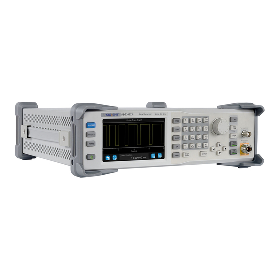
SIGLENT Figure 1-2 Front Panel Figure 1-3 Rear Panel Interface Test The SSG3000X series signal generator is designed with three standard interfaces: USB Host, USB Device, and LAN. Being connected to other instruments via these interfaces enables the signal generator to achieve additional capabilities. - Page 8 SIGLENT successfully recognized. Figure 2-1 USB drive has been properly recognized 8 SSG3000X Service Manual...
-
Page 9: Usb Device Test
SIGLENT USB Device Test To test if the USB Device interface is operating normally. Tools: ● A computer with USB interface that is compatible with running National Instruments NI-MAX software ● A standard USB cable (Type A-B) ● NI-MAX software Steps:... - Page 10 SIGLENT LAN Port Test Use to test the LAN interface functionality. Tools: ● A computer with functional LAN interface ● A standard LAN cable Steps: 1. Connect the signal generator and the computer using a LAN cable via LAN interface.
- Page 11 SIGLENT 4. Select Manual Entry of LAN instrument, select Next, and enter the IP address as shown. Click Finish to establish the connection: NOTE: Leave the LAN Device Name BLANK or the connection will fail. SSG3000X Service Manual 11...
- Page 12 SIGLENT 4. After a brief scan, the connection should be shown under Network Devices: 5. Right-click on the product and select Open NI-VISA Test Panel: 6. Click “Input/Output” option button and click “Query” option button. If everything is connected and operating correctly, the Read operation information returned shown below will appear.
-
Page 13: Performance Verification Test
Table 3-1 Test equipment Equipment Specification Qty. Recommended Signal Analyzer 9 kHz~3.2 GHz Keysight N9020 Power Meter 6 GHz R&S NRP6A SIGLENT SDG1050 Frequency Counter 10 MHz With OCXO Attenuator 10 dB RF switch 18 GHz SMA-N Cable 6 GHz BNC Cable... -
Page 14: 10 Mhz Output Accuracy Test
SIGLENT 10 MHz output accuracy test Specification Reference frequency 10.000000 MHz Initial calibration accuracy <0.2 ppm OCXO REF IN 10MHz OUTPUT SSG3000X SDG6000X Figure 3-6 Connecting test instruments for frequency accuracy Steps: 1. Connect ref out port of the signal generator to the channel A of the SDG6000X. - Page 15 SIGLENT Figure 3-1 Absolute amplitude accuracy connections Test Procedures 1. Connect the output terminal of the SSG3000X with the power meter, as shown in Figure 3-1 (a). 2. Set the SSG3000X to output a sine waveform with -10 dBm amplitude. Then modify the output frequency of the SSG3000X according to Table 2-2 and enable the RF output switch RF.
- Page 16 SIGLENT 9. System Error (the input attenuation of the signal analyzer is 10 dB) = A2 - A1 and record the measurement result. 10. Keep the connection shown in Figure 3-1 (b) unchanged, press Mode Preset to restore the signal analyzer to its factory setting and set the output amplitude of the SSG3000X according to Table 2-3.
-
Page 17: Second Harmonics
SIGLENT 51.33 MHz 533 MHz <0.7 1.933 GHz 2.433 GHz 2.933 GHz Table 2-6 Reference -50 dbm Value SSG3000X Signal Global Amplitude Limit Pass/Fail Output Analyzer Error Accuracy Measurement Value A3 103 kHz 1.33 MHz 51.33 MHz <0.7 533 MHz 1.933 GHz... - Page 18 SIGLENT Test Connection Diagram Test Procedures 1. Synchronize the SSG3000X and signal analyzer. Connect the RF output terminal of the SSG3000X with the RF input terminal of the signal analyzer. 2. Configure the SSG3000X: a. Set the output frequency follow the table 2-8 b.
-
Page 19: Internal Am Modulation Test
SIGLENT 2512 MHz >30.0 2912 MHz >30.0 Internal AM modulation test Specification Amplitude Modulation Modulation source internal, external, internal + external AM depth setting range 0 %~100 % Resolution of m setting 0.1 % AM Accuracy =1 kHz < 4 % of m setting+1 % =1 kHz, m≤30 %,... - Page 20 SIGLENT Set the amplitude to -10 dBm. Enable the AM switch. Set the modulation source to internal. Set the modulation depth to 30%. Set the modulation rate to 1 kHz. Set the modulation waveform to “Sine”. Enable the modulation output switch MOD.
-
Page 21: Internal Fm Modulation Test
SIGLENT Internal FM modulation test Specification Frequency Modulation Modulation source internal, external, internal + external Maximum FM deviation *1 MHz (typ.) Resolution of m setting 0.1% of m setting or 1 Hz, whichever is larger FM Deviation Accuracy =1 kHz, internal <2% of m setting+20 Hz... - Page 22 SIGLENT Set the amplitude to -10 dBm. Enable the FM switch. Set the modulation source to internal. Set the modulation deviation to 500 kHz. Set the modulation rate to 1 kHz. Set the modulation waveform to “Sine”. Enable the modulation output switch MOD.
-
Page 23: Internal Φm Modulation Test
SIGLENT Internal ΦM modulation test Specification Phase Modulation Modulation source internal, external, internal + external Maximum ΦM deviation *5 rad Resolution of m setting 0.1 % of m setting or 0.01 rad, whichever is larger ΦM Deviation Accuracy =1 kHz, internal, <2 % of m setting+0.05 rad... -
Page 24: Pulse Modulation Test
SIGLENT Enable the ΦM switch. Set the modulation source to internal. Set the modulation deviation to 2.5 rad. Set the modulation rate to 1 kHz. Set the modulation waveform to “Sine”. Enable the modulation output switch MOD. Enable the RF output switch RF. - Page 25 SIGLENT Raise/fall time 10 % to 90 % of RF amplitude <50 ns (10 %/90 %) Pulse repetition Setting range 40 ns~300 s time Test Devices 1. Signal Analyzer × 1 2. Dual-BNC Cable × 1 3. Dual-N Cable × 1...
-
Page 26: Exit I Q Modulation Test
SIGLENT Set the center frequency to 1Ghz. Set the span to 0 Hz. Set the reference level to 0 dBm. Set the input attenuation to 10 dB. Set the resolution bandwidth to 100 Hz. Set the video bandwidth to 100kHz. - Page 27 SIGLENT Test Procedures 1. Synchronize the SSG3000X and signal analyzer. Connect the RF output terminal of the SSG3000X with the RF input terminal of the signal analyzer. Connect the USB DEVICE connector of the SSG3000X with the USB interface of the PC as shown in figure.
-
Page 28: Lf Ac Test
SIGLENT f) Enable the modulation output switch mod. g) Enable the RF output switch RF. 5. Configure the signal analyzer: a) Press mode-89601 VSA to enter the vector signal analysis interface. b) Press demodulator-digital demod c) Press grid 2*2 to show the EVM value. - Page 29 SIGLENT of the power sensor as shown in figure above. 2. Enable LF output switch. Select Sine waveform of the generator and set the amplitude to 0 dBm and then step through the frequencies listed below in sequence. Then, set the amplitude to -20 dBm and repeat the frequency steps.
-
Page 30: Lf Dc Test
SIGLENT LF DC test Specification ±(1%+3 mV) DC Offset error Test Devices 1. Digital Multimeter × 1 2. Banana-to-single-BNC Cable × 1 s Test Connection Diagram Digital Multimeter Banana-to-single BNC Cable Test Procedures 1. Connect the LF output terminal of the SSG3000X with the Voltage input terminal of the Digital Multimeter as shown in figure above. -
Page 31: Assembly Procedures
SIGLENT Assembly Procedures This chapter describes how to remove the major modules from the SSG3000X signal generator. To install the removed modules or replace new modules, please follow the corresponding operating steps in reverse order. This chapter includes the following topics: ... -
Page 32: List Of Modules
SIGLENT List of Modules The following removable modules are listed in the order of performing disassembly procedures. Table 4-1 List of modules Number of Module Module Outer cover Front-Panel Power module Main board Zynq board IQ-E board RF connector LCD ,Keyboard... -
Page 33: Disassembly Procedures
SIGLENT Disassembly Procedures This section describes how to remove and install the modules listed above in the signal generator in detail. Complete disassembly will be best achieved using the following operating steps. Removing the Outer Cover SCREW ×2 SCREW ×2 SCREW ×4... -
Page 34: Removing The Iq Module
SIGLENT Removing the IQ Module Power cable RF cable NUT × 2 SCREW × 5 Removal steps: 1、.Disconnect the power cable and the RF cable 2、Remove the five screws located on the IQ board. 3、Next, remove the IQ board. To install the IQ board, please follow these same steps in reverse order. -
Page 35: Removing The Power Module
SIGLENT Removing the Power Module Power cable SCREW × 5 Removal steps: 1、Disconnect the power cable 2、Remove the five screws located on the metal shell 3、Next, remove the Power Module To install the Power Module, please follow these same steps in reverse order. -
Page 36: Removing The Main Board
SIGLENT Removal steps: 1、Unlock the hook as show in the above figure 2、Remove the control board Removing the Main Board × 6 Screen cable SCREW × 14 Removal steps: If the device has the IQ_E option, remove the IQ board first 1. -
Page 37: Removing The Front Panel
SIGLENT 2. Disconnect the screen cable and RF cable connected to the main board module from the fronted module. 3. Remove the screws located on the main board. 4. Remove the six nuts from the back BNC terminal. To install Main Board, please perform these steps in reverse order. -
Page 38: Removing The Lcd, Keyboard
SIGLENT Removing the LCD, Keyboard KNOB SCREW × 13 SCREW × 4 Figure 4-5 Removing the LCD and keyboard Removal steps: 1. Remove the thirteen screws on the keyboard. 2. Remove the four screws located on the edge of the display module.
Need help?
Do you have a question about the SSG3032X-IQE and is the answer not in the manual?
Questions and answers