Table of Contents
Advertisement
Quick Links
Advertisement
Table of Contents

Related Manuals for SIGLENT SSG3032X


Summary of Contents for SIGLENT SSG3032X
- Page 1 SSG3000X Signal Generator User Manual UM0803X -E01A...
- Page 2 Declaration SIGLENT products are protected by patent law worldwide SIGLENT reserves the right to modify or change parts of or all the specifications or pricing policies at company’s sole decision. Information in this publication replaces all previously corresponding material.
-
Page 3: General Safety Summary
SIGLENT General Safety Summary Carefully read the following safety precautions to avoid any personal injury or damage to the instrument and any products connected to it. To avoid potential hazards, please use the instrument as specified. Use Proper AC Power Line Only the power cord designed for the instrument and authorized by local country should be used. - Page 4 SIGLENT regularly. Avoid Exposed Circuit or Components Do not touch exposed contacts or components when the power is on. Do Not Operate Without Covers Do not operate the instrument with covers or panels removed. Use Only the Specified Fuse. Keep Product Surfaces Clean and Dry.
-
Page 5: Safety Terms And Symbols
SIGLENT Safety Terms and Symbols Terms used in this manual: DANGER: Indicates an injury or hazard that may immediately happen. WARNING: Indicates an injury or hazard that may not immediately happen. CAUTION: Indicates that a potential damage to the instrument or other property might occur. -
Page 6: Ssg3000X Overview
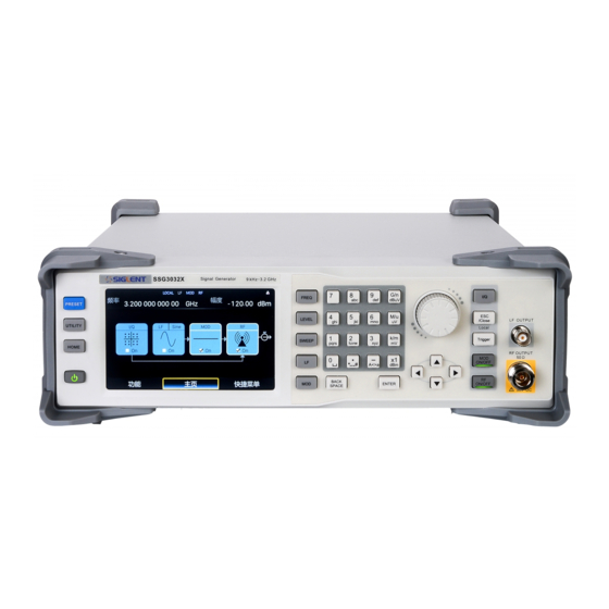
SIGLENT SSG3000X Overview The SIGLENT SSG3000X series is a bench top RF signal source, with an output frequency range from 9 kHz to 3.2 GHz. It features light weight, small size, and convenient interface make it ideal for R&D, education, production, and maintenance. -
Page 7: Table Of Contents
SIGLENT Contents Guaranty and Declaration ......................II General Safety Summary ......................III Safety Terms and Symbols ......................V SSG3000X Overview ........................ VI Chapter 1 Quick Start ......................1 Appearance size ....................2 Preparing for Use ....................3 1.2.1 Adjust the Supporting Legs ................3 1.2.2... - Page 8 SIGLENT SweepSetting ..................... 29 2.3.1 Sweep State....................29 2.3.2 Step Sweep....................29 2.3.3 List sweep ....................30 2.3.4 Direction ...................... 32 2.3.5 Sweep Mode ....................32 2.3.6 Trigger Mode ....................32 2.3.7 Point Trigger....................33 2.3.8 Trigger Slope ....................34 Modulation Setting .....................
- Page 9 SIGLENT 2.9.4 Esc/Close ....................78 2.9.5 Mod ON/OFF ....................79 2.9.6 RF ON/OFF....................79 Chapter 3 Application Examples..................80 Output RF signal ....................80 Output a modulated signal ................. 81 Output a pulse train .................... 83 Output IQ modulated signal ................85 Test the OIP3 of Active Devices with the SSG3000X ........
-
Page 11: Chapter 1 Quick Start
SIGLENT Chapter 1 Quick Start Subjects in this chapter: Appearance Appearance size Preparing for Use The Front Panel Rear Panel User interface Touch operation Parameter setting Help information SSG3000X User Manual 1... -
Page 12: Appearance Size
SIGLENT 1.1 Appearance size Figure 1-1 Front View Figure 1-2 Top View Figure 1-3 Side View SSG3000X User Manual 2... -
Page 13: Preparing For Use
SIGLENT 1.2 Preparing for Use 1.2.1 Adjust the Supporting Legs For benchtop operation, you may want to use the supporting legs.Adjust the supporting feet appropriately to tilt the RF signal source upwards. Figure 1-4 before adjusting Figure 1-5 after adjusting 1.2.2 Connect to AC Power Supply... -
Page 14: The Front Panel
SIGLENT 1.3 The Front Panel Figure 1-7 the Front Panel Table 1-1 Front Panel Description Description Description Function key Knob LF output RF output Direction key Digital keyboard Touch screen display area Power button 1.3.1 Front Panel Function Keys Table 1-2 Function keys description... -
Page 15: Front Panel Key Backlight
SIGLENT parameters. Set LF state, LF level, LF frequency and other related parameters. Set various modulation parameters (AM, FM, PM and PULSE). Set IQ related parameters ESC/Close During the parameter or editing process, pressing this key will clear the input of the active function area and exit the parameter input state. -
Page 16: Digital Keyboard
SIGLENT modulation, and the lights will turn off. RF ON/OFF When the RF signal is turned on, the back light is on, and the radio signal is turned off. 1.3.3 Digital keyboard The front panel of the RF signal source provides a numeric keypad (as shown below). The... - Page 17 SIGLENT frequency, press this key to set the units as GHz, if the input is a time-related parameter, press this key to set the unit tons. When setting the amplitude, press this key to set the units as uV.When setting the frequency, press this key to set the units as MHz, if the input is a time-related parameter, press this key to set the unit to us.
-
Page 18: Front Panel Connectors
SIGLENT 1.3.4 Front Panel Connectors Figure 1-9 front panel connectors LF (low frequency) output Output the low frequency signal. This is a BNC connection .The output can also be configured to source the modulation waveform for FM and PM modulation types. -
Page 19: Rear Panel
SIGLENT 1.4 Rear Panel Figure 1-10 Rear Panel AC power input terminal The RF signal source can operate with AC power from specifications of the AC power supply supported by RF signal source are 100 V - 240 Vat 45 Hz - 440 Hz. Please connect the RF signal source to the AC power supply with the supplied power cord. - Page 20 SIGLENT The RF signal source can be used as the "main device" to connect to the external USB device. The interface reads the trace or state file from the U disk, or stores the current instrument state or trace to the U disk, and can also save the content displayed on the current screen in .BMP format to the U disk.
- Page 21 SIGLENT If the instrument uses an internal reference source, the [10MHz OUT] connector can output a 10MHz clock signal generated by the instrument and can be used to synchronize other devices. PULSE IN/OUT The function of the connector is determined by the current mode of pulse modulation.
- Page 22 SIGLENT Used to input an external modulated I baseband signal when the external IQ modulation mode is on. 13. Q INPUT Used to input an external modulated Q baseband signal when the external IQ modulation mode is on. Note: [I INPUT] and [Q INPUT] connectors are only available on models equipped with IQ modulation.
-
Page 23: User Interface
SIGLENT 1.5 User interface Figure 1-11 User Interface Prompt status bar Display Local (local), Remote (remote). When Remote is displayed, the instrument is being controlled by a remote computer and the front panel input will be locked .To unlock the front panel (enter Local mode).Esc/Close to quit. - Page 24 SIGLENT RF frequency RF output frequency setting. When the scan type is "frequency" or "frequency & amplitude", the frequency scanning progress bar is displayed. RF level RF output level setting. When the scan type is "amplitude" or "frequency &litude", the level scanning progress bar is displayed.
-
Page 25: Touch Operation
SIGLENT 1.6 Touch operation The RF signal source provides a 5 inch capacitive touch screen to support various gesture operations. Including: Click on the screen parameters or menu to edit the parameters. Left or right slide switches menus. -
Page 26: Parameter Setting
SIGLENT 1.7 Parameter setting P arameter input can be performed through touch screen, keypad and digital keys, knob or direction keys. This section introduces an example of three parameter setting methods by setting the center frequency to 100 MHz. Using the digital keyboard 1) Press FREQ;... -
Page 27: Help Information
SIGLENT 1.8 Help information The built-in help system of RF signal source provides help information for each function and menu option on the front panel. Press UTILITYbutton and select help. The center of the screen will pop up to help. -
Page 28: Chapter 2 Front Panel Operation
SIGLENT Chapter 2 Front Panel Operation This chapter describes in detail the function keys at the front panel and the associated functions. Subjects in this chapter: Frequency Setting LevelSetting Sweep Setting Modulation Setting LF Setting ... -
Page 29: Frequency Setting
SIGLENT 2.1 Frequency Setting The value of the RF frequency is displayed in the header of the display (― Freq‖). This field provides the direct input of the RF frequency. Alternatively, you can enter the RF frequency in the ― Freq‖ dialog. -
Page 30: Freq Offset
SIGLENT 2. Touch screen operation Click on SHORTCUT->FREQ->Frequency to enter the interface of RF output frequency setting. Click the frequency parameter, then pop up the keypad interface, then click the number symbol in the keypad to change the value. Click the unit to modify the unit. -
Page 31: Phase Offset
SIGLENT 2. Touch screen operation Click SHORTCUT->FREQ-> Freq Offset to enter the interface of frequency offset setting. Click the frequency offset parameter, and then pop up the keypad interface, then click the number symbol in the keypad to change the value. Click the unit to modify the unit. - Page 32 SIGLENT Press ENTER or press the knob to enter the parameter editing state, and then use the left and right direction keys to move the cursor to the desired position. Press the up and down direction keys, rotate the knob or press the numeric keypad to modify the value.
-
Page 33: Levelsetting
SIGLENT 2.2 LevelSetting The value of the RF level is displayed in the level text field locatedin the header of the display (labeled― Level‖).This field provides the direct input of the RF level value .Alternatively, you can enter the level in the level dialog. -
Page 34: Level Offset
SIGLENT Use the numeric keypad to input the desired value and press the unit button to select the desired unit. Optional units are dBm, dBuV, uV, mV, V, nW, uW, mW and W. Press ENTER to select the current unit by default. -
Page 35: Alc State
SIGLENT mark to confirm. Press ENTER or press the knob to enter the parameter editing state, and then use the left and right direction keys to move the cursor to the desired position. Press the up and down direction keys, rotate the knob or press the numeric keypad to modify the value. -
Page 36: Flatness
SIGLENT Keypad operation Press LEVEL-> ALC State to expand the drop-down box, then rotate the knob or press the up and down direction keys to select ALC state. Touch operation Click on SHORTCUT->LEVEL->ALC state to select ALC state. ALC has three functions: "Off", "On" and "Auto‖: ●... - Page 37 SIGLENT frequency point within the frequency range of the instrument to compensate for losses in the cable, or losses caused by other equipment. Flatness Menu Keypad operation Press LEVEL->Flatness to make the focus fall on the flatness menu, then press the knob or ENTER key to switch flatness status.
- Page 38 SIGLENT Press to empty any number of rows. Load Press to enter the file save/call page, select and load existing flatness correction files, see "file management" for details. Save Press to enter the file save/call page, save the correction data in the list, see "file management"...
-
Page 39: Sweepsetting
SIGLENT 2.3 Sweep Setting When the RF sweep function is enabled, the RF signal is output from the N-type connector of [RF OUTPUT 50Ω] on the front panel. Note: The RF signal will be on only when the RF switch is on. -
Page 40: List Sweep
SIGLENT automatically when the other is on. Start Freq: Initial frequency setpoint of the sweep. Stop Freq: Final frequency setpoint of sweepsetting the stop sweep frequency. Start Level: Initial amplitude level set point of the sweep Stop Level:Final amplitude level set point of the sweep. - Page 41 SIGLENT As show in the figure, the table edit page consists of the operating button on the left of page, the table on the middle of the page and the menu button on the right side. Inset line: Click the to inset a new line under the current cursor.
-
Page 42: Direction
SIGLENT Each line parameter represents the setting of each sweep point: Number: Indicates the row number of the sweep point. Frequency: Indicates the frequency of the sweep point. Level: Indicates the level of the sweep point. Time: Indicates the dwell time of the sweep point. -
Page 43: Point Trigger
SIGLENT ― Auto‖, ― Key‖, ― Bus‖ and ― Ext‖. Click the drop-down box of the trigger mode to select the desired type: Auto: The default mode. If the sweep mode is ― continuous‖, just select one sweep type to start a sweep. If the sweep mode is ― single‖, then click the Execute single sweep button to start a one time sweep. -
Page 44: Trigger Slope
SIGLENT type to start and sweep through each point continuously in one sweep cycle. If the sweep mode is ― single‖, first click Execute single sweep button to sweep through each point in one sweep cycle. Key: If the sweep mode is ― continuous‖, the device will sweepone point-at-a-time after ... - Page 45 SIGLENT arrives. Negative: A sweep is triggered when the falling edge of the external trigger signal arrives. Note: The trigger edge control is displayed only when the trigger mode or point trigger mode is ― Ext‖, and is hidden in other cases.
-
Page 46: Modulation Setting
SIGLENT 2.4 Modulation Setting 2.4.1 Amplitude Modulation (AM) Amplitude Modulation (AM) is a technique for delivering information by linearly varying the amplitude of anRF carrier signal. AM source can be selected as an internal source, external source or internal source + external source. - Page 47 SIGLENT 2.4.1.2 AM Source An internal and/or external source can be selected for amplitude modulation. MOD->AM->AM Source to set ― Int‖ or ― Ext‖ or ― Int + Ext‖. The default is ― Int‖. wheninternal modulation is selected, the AM Shape, AM frequency, and AM depth are controlled by the instrument.The internal modulation setting uses the LF generator as...
- Page 48 SIGLENT 2.4.1.4 AM Rate Select MOD->AM-> AM Rate, and setthe AM rate. Sine wave modulation frequency range is 0.01Hz~100kHz Square wave modulation frequency range is 0.01Hz~20kHz 2.4.1.5 AM Depth Set the modulation depth in percent. Select MOD->AM->AM Depth, and then set AM depth.
-
Page 49: Frequency Modulation (Fm)
SIGLENT 2.4.2 Frequency Modulation (FM) Enter the FM interface Click the MOD icon in the main interface to enter the MOD interface. The MOD interface displays the AM page by default. Then switch to the FM modulation page by clicking or sliding left. - Page 50 SIGLENT 2.4.2.3 FM Shape Select MOD->FM-> FM Shape. After setting to ― Int‖ or ― Int+Ext‖, you can select FM waveform as ― Sine‖ or ― Square‖. 2.4.2.4 FM Rate Select MOD->FM-> FM Rate, you can set the FM rate.
-
Page 51: Phase Modulation (Pm)
SIGLENT modulation sensitivity. External modulation sensitivity The display shows the unit offset quantized by the amplitude of the externally modulated signal, which is equal to the maximum offset when the external modulation input is full scale. When the ― Int+Ext‖ modulation source is enabled, the internal and external each account for 50% of the maximum offset, so when the external source inputs a full scale signal, it only accounts for 50% of the maximum output offset. - Page 52 SIGLENT Enter the PM modulation page directly through the shortcut menu. Enter the MOD interface via the MOD button and switch to the PM modulation page. 2.4.3.1 PM State Select MOD ->PM->PM State to turn PM on or off. 2.4.3.2 PM Source Select MOD ->PM->PM Source to set ―...
- Page 53 SIGLENT The square wave modulation frequency range is 0.01Hz~20kHz 2.4.3.5 PM Deviation The setting range is0.00001rad~N × 5rad. For the definition of N, refer to the data sheet. When the modulation source is set to ― Int ― , the set value is actually the frequency ...
-
Page 54: Pulse Modulation (Pulse)
SIGLENT 2.4.4 Pulse Modulation (PULSE) Pulse Modulation represents the process of modulating an RF carrier signal with a pulse signal as a modulated signal. 2.4.4.1 Pulse State Select MOD->PULSE->Pulse Stateto turn Pulse on or off. 2.4.4.2 Pulse Out Select MOD->PULSE->Pulse Outto turn Pulse Out on or off. The default is off. - Page 55 SIGLENT 2.4.4.3 Pulse Source Select MOD->PULSE->Pulse Source to set ― Int‖ or ― Ext‖. The default is ― Int‖. 1. Int Use the internal LF generator as the modulation signal source for PM. You can set Pulse Mode, Pulse Period, and Pulse Width and so on.
- Page 56 SIGLENT Double: Generate two pulse signals in one pulse period. At this time, the two settings ― Double Pulse Delay‖ and ― #2 Width‖ are shown. Train: Multiple pulse signals in one pulse period. At this time, the pulse sequence ...
- Page 57 SIGLENT mode is ― Single‖ or ― Double‖. 2.4.4.7 Pulse Width The pulse width indicates the duration when the pulse signal is at a high level. The width of the first pulse of the single pulse modulated signal or the double pulse modulated signal can be set by touching screen keyboard or pressing the front panel keypad.
- Page 58 SIGLENT 2.4.4.10 Trigger Out The default is ― off‖, Click the slide switch to switch the trigger output switch status. On: Turn on the trigger output function. At this time, the signal source outputs the trigger signal generated by the internal pulse generator from the [TRIG IN/OUT] connector on the rear panel.
- Page 59 SIGLENT on the rear panel. Each time a TTL pulse signal of the specified polarity is received, the source initiates a pulse modulation within its active level. At this point, the ― Trig Polarity‖ setting will be displayed and the ― Trig Slope‖ setting will be hidden.
- Page 60 SIGLENT Inverse: Trigger a pulse modulation during the effective time when the external gate signal is not high. Note: This setting item will be hidden when the modulation source is ― Ext‖ or the pulse trigger is not ― Ext Gate‖.
- Page 61 SIGLENT Return to the previous level: Click the button to return to the previous menu. Clear list: Click the button to clear and reset the current list. View the pulse sequence diagram: Click the button to enter the pulse sequence diagram page.
- Page 62 SIGLENT As shown, the page consists of the upper drawing area and the lower control area: Plot area: A schematic diagram of the waveform generated from the data entered in the current pulse sequence table. The vertical direction represents the high and low level changes of each pulse signal in the pulse sequence, and the position of the high and low levels in the direction is unchanged;...
- Page 63 SIGLENT The scaling operation for the drawing area can be achieved in the following ways: Zoom in, zoom out, restore and pan through the Control Area's , and Zoom Position parameter controls. From the web interface, you can press the left mouse button, select the area to be ...
-
Page 64: Lf Setting
SIGLENT 2.5 LF Setting 2.5.1 LF Source The SSG3000X has an internal low-frequency signal generator that can be used as an internal source for low-frequency signal output or analog modulation. When output as a low-frequency signal, the LF output supports several common waveforms, and the frequency and amplitude of the low-frequency signal can be set. -
Page 65: Lf Sweep
SIGLENT 2.5.1.5 LF Shape Select LF-> LF Source->LF Shape, you can select the LF output signal waveform. Current waveform types are ― sine wave‖, ― square wave‖, ― Sawtooth wave‖, ― triangle wave‖, and ― DC‖. The default LF output signal is the ― sine wave‖ waveform.LF phase 2.5.1.6... - Page 66 SIGLENT 2.5.2.4 Center Freq Select LF->LF Sweep->Center Freq to set the center frequency. 2.5.2.5 Freq Span Select LF->LF Sweep ->Freq Span to set the frequency Span. 2.5.2.6 Direction Select LF-> LF Sweep ->Sweep Direction. to set the sweep direction. 2.5.2.7 Sweep Times Select LF->LF Sweep ->Sweep Time to define the duration of the individual sweep steps.
- Page 67 SIGLENT instrument waits for the next trigger event. 3. Ext Generate a single sweep cycle when an external trigger event occurs. 2.5.2.9 Sweep Shape Select LF->LF Sweep->Sweep Shape to select the waveform shape of the sweep signal. 1. Sawtooth The sweep runs from the start to the stop frequency. Each subsequentsweep starts at the start frequency that means the shape ofthe sweep sequence resembling a Sawtooth.
-
Page 68: Utility
SIGLENT 2.6 Utility 2.6.1 System 2.6.1.1 Setting Language Set the display language of SSG3000X. SSG3000X supports Chinese/English menus, help and interface display. Press UTILITY->Setting->Language to expand drop down list, and then select the desired language. Power On Set the type of parameter configuration to be loaded when the instrument startup. - Page 69 SIGLENT User: The user specified configuration will be loaded when PRESET is pressed. After ― User‖ is selected, click button to load the configuration file. For detailed operation procedure please refer to ― Store/Recall‖ Factory Default Restore the instrument configuration to factory settings.
- Page 70 SIGLENT Flatness null Sweep List sweep Keep only one default scan point Mode Pulse Train Keep only one default pulse Beeper Set whether the beeper make a sound when clicking any button, input box or check box. Press UTILITY->Setting ->Beeper to switch the beeper state.
- Page 71 SIGLENT Time Setting Set the display time of the instrument. Press UTILITY->Setting ->Time Setting, then move the cursor to specified location and change the time by inputting the value. 2.6.1.2 System Info Press UTILITY->System Info to view the instrument's system information, including: Startup Times ...
- Page 72 ― siglent‖.) 3. GPIB Setting Set the GPIB address from 1 to 30. SSG3000X must use the SIGLENT USB-GPIB interface (optional) connected to the USB Host port located on the rear panel. Press UTILITY->Interface ->GPIB Address, and then press number keys to input value,...
- Page 73 SIGLENT finally press ENTER to make the setup effective. 2.6.1.4 Self Test 1. Press Utility ->Self test to enter the self test menu, including:LCD Test SSG3000X cycles through the red, green and blue pixels of the display to verify whether there are dot defects on the screen.
- Page 74 SIGLENT 2.6.1.5 Shutdown Press UTILITY->Shutdown to power off the instrument according to operating hints on the interface. 2.6.1.6 Preset Reset parameter settings according to the type of presetselected. Press UTILITY->Preset, to reset the parameters. 2.6.1.7 Update Press UTILITY->Update, and select the update file. Then click Recall to update the system software.
-
Page 75: Store/Recall
2.6.1.10 Contact Us Press UTILITY->Contact Us to view the contact information for SIGLENT. You can contact us to solve the problems meet in practical use.You can also write info@siglent.com... - Page 76 SIGLENT State file: .xml file: State saving file. Update file: .CFG file: Configuration update file; .ADS file: System update file. New Dir _____ Click NewDir to create new folders. Press �� <> �� to switch the case of letter when entering the name of a new file.
- Page 77 SIGLENT Click Save to save the file with corresponding type according to the type of data. SSG3000X User Manual 67...
-
Page 78: Power Sensor
SIGLENT 2.7 Power Sensor The SSG3000X can be connected to a USB power sensor via the USB Host interface.For the first connection, please refer to the ― Option‖ to activate the power meter software. Then, connect the USB power sensor to the USB Host connector on the rear panel. If the ―... - Page 79 SIGLENT 2.7.1.2 Sensor State The default is ― off‖. Activate/deactivate level measurement by the power sensor. On:Turn on the power sensor measurement function, and the measurement control refreshes the power sensor measurement value in real time. Off:Turn off the power sensor measurement function.
- Page 80 SIGLENT 2.7.1.6 Auto Zero When the power meter is zeroed, the zero measurement deviation and noise influence can be reduced, and the accuracy of the RF power measurement can be improved. Disable: The zero buttons will be hidden. Internal Zeroing: In this way, the power sensor remains connected to the RF signal ...
- Page 81 SIGLENT 2.7.1.8 Level Offset The default is ― Off‖.Click the slide switch to switch the power offset switch status. On: The values can be set by the touch screen keyboard or front panel keypad.The displayed value will be the actual measurement plus the offset.This feature makes measurements easier when there are amplifiers and attenuators in the middle of the signal chain.
-
Page 82: Level Control
SIGLENT 2.7.2 Level Control As shown in the example, the sensor measures a proportional power in defined time intervals, derived from a coupler. It considers optionally the given S-parameters and returns the results to the generator. The signal generator compares the measured level with the set value and adjusts its output level accordingly.This allows you to control the... - Page 83 SIGLENT 2.7.2.2 Measurement Indicate the current reading of the sensor. Select the unit used for result display. You can change the unit for the results display: dBm, dBμV, uV, mV, V, nW, uW, mW, W. 2.7.2.3 Target Level Specify the nominal level expected at the input of the sensor. The signal generator adjusts the output power accordingly, in order to meet the target value at the sensor input, and thus the power required at the DUT.
-
Page 84: I/Q Modulation
SIGLENT 2.8 I/Q Modulation I/Q modulation, i.e. two orthogonal signals (carriers with the same frequency, phase difference of 90°, generally expressed by Sin and Cos) and I (In-Phase, in-phase component) and Q (Quadrature Phase) signals are respectively modulated by carrier and transmitted together, thereby improving spectrum utilization. -
Page 85: Shortcut Keys
SIGLENT 2.9 Shortcut Keys 2.9.1 Preset Recall the preset setting and restore the signal generator to a specified status. Press UTILITY->Setting ->Preset Type to select ― Default‖ or ― User‖. Press PRESET to load the factory settings listed in the following table or ... - Page 86 SIGLENT Step Sweep Step Sweep State Start Freq 3.2 GHz Stop Freq 3.2 GHz Start Level -110dBm Stop Level -110dBm Sweep Points Dwell Time 30ms Sweep Space Linear Sweep Shape Sawtooth List Sweep List Sweep State MOD State AM State...
- Page 87 SIGLENT PM State PM Source PM Shape Sine PM Rate 10kHz PM Deviation 1rad Pulse Pulse State Pulse Source Pulse Mode Single Pulse Period 10ms Pulse Width Double Pulse Delay #2 Width Trigger Out Pulse Trigger Auto Trig Delay 140 ns...
-
Page 88: Home
SIGLENT LF Phase 0deg LF Sweep Sweep State Start Freq 500Hz Stop Freq 1.5kHz Center Freq 1kHz Freq Span 1kHz Sweep Time Trigger Mode Auto Sweep Shape Sawtooth Trigger Mode Linear Direction 2.9.2 Home Return to the home page. 2.9.3 Trigger When the trigger mode of the sweep is key trigger, press this key once to trigger a sweep. -
Page 89: Mod On/Off
SIGLENT In dialog boxes that contain an ― Esc‖ button it closes the dialog box. Exit the current menu and return to the previous menu. 2.9.5 Mod ON/OFF Enable/disable modulation on the RF output. When enabled, the backlight will light, the screen status bar MOD will change from gray to blue, and RF output modulation will be activated. -
Page 90: Chapter 3 Application Examples
SIGLENT Chapter 3 Application Examples Output RF signal Output a RF signal with a frequency of 3GHz and amplitude of 0dBm from the RF OUTPUT 50 connector. Restore factory settings A) Press UTILITY or the touch screen to set System -> Setting -> Preset Type->... -
Page 91: Output A Modulated Signal
SIGLENT 3.2 Output a modulated signal In this section, we will show how to enable modulation by configuring the SSG to output an AM modulated signal with the following characteristics: Carrier frequency is 1GHz, the carrier amplitude is -10dBm, the AM modulation depth is 80%, the modulation frequency is 10 kHz, and the modulation waveform is a sine wave. - Page 92 SIGLENT Press MOD On/OFF and then press RF ON/OFF. The backlights of MOD On/OFF and RF ON/OFF will be illuminated. RF and MOD labels in the status bar will change from gray to blue. At this time, the signal on the [RF OUTPUT 50Ω ] connector will match the settings configured above.
-
Page 93: Output A Pulse Train
SIGLENT 3.3 Output a pulse train A pulse train is a user-defined sequence of high and low RF levels with specific time durations for each part. In this example, we will show how to configure the RF source to output the following pulse train:... - Page 94 SIGLENT negative pulse width to 20ms, and the count to 2. D) After clicking, you can click on the left side to see the schematic diagram of the pulse train as follows. 4.Set the Pulse State to on. 5.Enable the RF modulation output Press MOD On/OFF and then press RF ON/OFF.
-
Page 95: Output Iq Modulated Signal
SIGLENT 3.4 Output IQ modulated signal The external modulation function (optional) of the SSG3000X and the SDG6000X series arbitrary waveform generator can be used as the baseband source to generate an IQ modulated signal. The following steps describe how to generate an IQ modulated signal with a modulation mode of 32QAM. - Page 96 SIGLENT As shown in the figure below, configure the SSG3000X and SDG6000X separately, and then enable the output of the SDG6000X, the IQ, MOD and RF output of the SSG3000X; SSG3000X User Manual 86...
- Page 97 SIGLENT At this time, the RF interface of the SSG3000X outputs an IQ modulation signal with a modulation mode of 32QAM, and the IQ modulation signal is connected to an IQ demodulation device to observe the demodulation characteristics of the IQ modulation signal;...
-
Page 98: Test The Oip3 Of Active Devices With The Ssg3000X
SIGLENT 3.5 Test the OIP3 of Active Devices with the SSG3000X OIP3 is a key indicator for evaluating the linearity of active devices. This can be tested using the SSG3000X with the SDG6000X series of arbitrary waveform generators. The following steps describe how to generate a two-tone continuous wave signal with a carrier frequency of 1 GHz and an interval frequency of 1 MHz to test the OIP3 of the active device. - Page 99 SIGLENT At this time, the RF interface of the SSG3000X outputs a two-tone continuous wave signal with a carrier frequency of 1 GHz and an interval frequency of 1 MHz. The signal is used as the input of the active device, and the output signal is tested to obtain the OIP3 characteristic as shown in the following figure.
- Page 100 SIGLENT oscillator leakage, it can be solved by alternately adjusting the Offset of I and Q. SSG3000X User Manual 90...
-
Page 101: Chapter 4 Programming Overview
SIGLENT Chapter 4 Programming Overview The SSG3000XSignal Generator features a LAN, USB Device, and SIGLENT GPIB—USB module interfaces. By using a computer with these interfaces, and a suitable programming language (Python, C+, .NET, etc, and NI-VISA software), users can remotely control the signal generatorusing standard SCPI (Standard Commands for Programmable Instruments) commands. -
Page 102: Connecting Via The Lan Port
SIGLENT Figure 4-1 USB Device The SSG will be detected automatically as a new USB hardware. 4.1.2 Connecting via the LAN port Refer to the following steps to finish the connection via LAN: Install NI-VISA on your PC for VXI driver. Or without NI-VISA, using socket or telnet in your PC’s Operating System. -
Page 103: Gpib: Connecting Via The Usb-Host Port
4.1.3 GPIB: Connecting via the USB-Host port Refer to the following steps to finish the connection via USB: Install NI-VISA on your PC for GPIB driver. Connect the SSG USB Host port to a PC’s GPIB card port, with SIGLENT USB-GPIB adaptor. Switch on the SSG Figure 4-4SIGLENT USB-GPIB Adaptor Press button on the front panel System→Interface→GPIB to enter the GPIB number. -
Page 104: Build Communications
SIGLENT 4.2 Build Communications 4.2.1 Build Communications Using VISA NI-VISA includes a Run-Time Engine version and a Full version. The Run-Time Engine version provides NI device drivers such as USB-TMC, VXI, GPIB, etc. The full version includes the Run-Time Engine and a software tool named NI MAX that provides a user interface to control the device. - Page 105 SIGLENT Set the install path, default path is ― C:\Program Files\National Instruments\‖, you can change it. Click Next, dialog shown as above. Click Next twice, in the License Agreement dialog, select the ― I accept the above 2 License Agreement(s).‖, and click Next, dialog shown as below: Click Next to run installation.
-
Page 106: Build Communications Using Sockets/Telnet
SIGLENT Now the installation is complete, reboot your PC. 4.2.2 Build Communications Using Sockets/Telnet Through the LAN interface, VXI-11, Sockets and Telnet protocols can be used to communicate with the SSG. VXI-11 is provided in NI-VISA, while Sockets and Telnet are commonly included in the operating system (OS) of many computers. -
Page 107: Remote Control Capabilities
SIGLENT 4.3 Remote Control Capabilities 4.3.1 User-defined Programming Users can use SCPI commands to program and control the signal generator. For details, refer to the introductions in ― Programming Guide‖. 4.3.2 Send SCPI Commands via NI MAX Users can control the signal generator remotely by sending SCPI commands via NI-MAX software. - Page 108 SIGLENT NOTE: The ― *IDN?‖ command (known as the Identification Query) returns the instrument manufacturer, instrument model, serial number, and other identification information. 4.3.2.2 Using LAN Select― Add Network Device‖, and select ― VISA TCP/IP Resource‖ as shown: Run NI MAX software.
- Page 109 SIGLENT After a brief scan, the connection should be shown under Network Devices: Click ― Open VISA Test Panel‖ option button, then the following interface will appear: SSG3000X User Manual 99...
-
Page 110: Web Control
SIGLENT Click ― Input/Output‖ option button and click ― Query‖ option button. If everything is OK, you will see the Read operation information returned as shown below. 4.3.1 Web Control With the new embedded web server, users can control the SSG through LAN from a web browser on PC or mobile terminals. -
Page 111: Chapter 5 Service And Support
SIGLENT sales representative. 5.2 Troubleshooting Before calling SIGLENT, or returning an SSG for service, perform the quick checks listed below. This check may eliminate the problem. If the problem remains still, please contact SIGLENT and provide your device information of the SSG (Get method: UTILITY->System Info). - Page 112 (3) If a key is not working, the numeric keyboard connection might be loose or the numeric keyboard is broken. Do not disassemble the instrument by yourself and contact SIGLENT. 3. Correct setting but incorrect waveform output (1)No RF output -Check that the signal cable is securely connected to the corresponding [RF OUTPUT...
- Page 113 SIGLENT -Check that the signal cable is securely connected to the corresponding [RF OUTPUT 50 Ω] port. -Check the cable for damage. -Check that both the MOD and RF button backlights are lit and that the modulation switch needs to be turned on.
- Page 114 SIGLENT -If the current scan type is set to Frequency, the amplitude value does not change. 5. USB device cannot be recognized: (1) Check if the USB device is connected to other instruments or the computer can work normally. (2) Confirm the flash type U disk device used. This instrument does not support the hard disk type U disk device.
-
Page 115: Chapter 6 Service And Support
(accessories for a period of one year) from the date of shipment from an authorized Siglent distributor. If the product proves defective within the respective period, SIGLENT will provide repair or replacement as described in the complete warranty statement. -
Page 116: Contact Us
SIGLENT 6.2 Contact Us China: SIGLENT TECHNOLOGIES CO., LTD. Add: Bldg. No.4 & No.5, Antongda Industrial Zone, 3rd Liuxian Road, Bao'an District, Shenzhen, 518101, China. Tel: + 86 755 3661 7876 Fax: + 86 755 3359 1582 Email: sales@siglent.com; Website: http://www.siglent.com/ens/ USA: SIGLENT Technologies America, Inc.
Need help?
Do you have a question about the SSG3032X and is the answer not in the manual?
Questions and answers