SIGLENT SSG3000X User Manual
Signal generator
Hide thumbs
Also See for SSG3000X:
- Programming manual (102 pages) ,
- Service manual (39 pages) ,
- User manual (116 pages)
Table of Contents
Advertisement
Quick Links
Download this manual
See also:
Service Manual
Advertisement
Table of Contents

Related Manuals for SIGLENT SSG3000X


Summary of Contents for SIGLENT SSG3000X
- Page 1 SSG3000X Signal Generator User Manual UM0803X -E01A...
- Page 2 Declaration SIGLENT products are protected by patent law worldwide SIGLENT reserves the right to modify or change parts of or all the specifications or pricing policies at company’s sole decision. Information in this publication replaces all previously corresponding material.
-
Page 3: General Safety Summary
Maintain Proper Ventilation Inadequate ventilation may cause increasing of the instrument’s temperature, which will eventually damage the instrument. So keep well ventilated and inspect the intake and fan SSG3000X User Manual III... - Page 4 Do Not Operate in an Explosive Atmosphere. In order to avoid damage to the device or personal injury, it is important to operate the device away from an explosive atmosphere. IV SSG3000X User Manual...
-
Page 5: Safety Terms And Symbols
WARNING: Indicates an injury or hazard that may not immediately happen. CAUTION: Indicates that a potential damage to the instrument or other property might occur. Symbols used on the instrument. Symbols may appear on the instrument: Hazardous Protective Warning Chassis Voltage Earth Ground Ground SSG3000X User Manual V... -
Page 6: Ssg3000X Overview
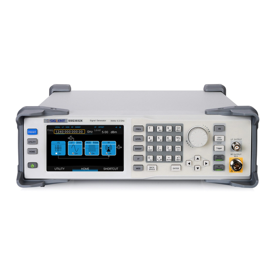
SIGLENT SSG3000X Overview The SIGLENT SSG3000X series is a bench top RF signal source, with an output frequency range from 9 kHz to 3.2 GHz. It features light weight, small size, and convenient interface make it ideal for R&D, education, production, and maintenance. -
Page 7: Table Of Contents
SIGLENT Contents Guaranty and Declaration ......................II General Safety Summary ......................III Safety Terms and Symbols ......................V SSG3000X Overview ........................ VI Chapter 1 Quick Start ......................1 Appearance size ....................2 Preparing for Use ....................3 1.2.1 Adjust the Supporting Legs ................3 1.2.2... - Page 8 Level Control ....................72 I/Q Modulation ....................74 2.8.1 Turning on I/Q modulation ................74 2.8.2 I/Q source ....................74 Shortcut Keys ..................... 75 2.9.1 Preset ......................75 2.9.2 Home ......................78 2.9.3 Trigger ......................78 VIII SSG3000X User Manual...
- Page 9 Output RF signal ....................80 Output a modulated signal ................. 81 Output a pulse train .................... 83 Output IQ modulated signal ................85 Test the OIP3 of Active Devices with the SSG3000X ........88 Chapter 4 Programming Overview ..................91 Remote Operation ....................91 4.1.1...
-
Page 11: Chapter 1 Quick Start
SIGLENT Chapter 1 Quick Start Subjects in this chapter: Appearance Appearance size Preparing for Use The Front Panel Rear Panel User interface Touch operation Parameter setting Help information SSG3000X User Manual 1... -
Page 12: Appearance Size
SIGLENT 1.1 Appearance size Figure 1-1 Front View Figure 1-2 Top View Figure 1-3 Side View SSG3000X User Manual 2... -
Page 13: Preparing For Use
1.2.2 Connect to AC Power Supply The RF signal source accepts 100-240V, 50/60/440Hz AC power supply. Please use the power cord provided to connect the instrument to the power source as shown in the figure below. Figure 1-6 Power Interface SSG3000X User Manual 3... -
Page 14: The Front Panel
Set frequency, frequency offset, phase offset and other related parameters. LEVEL Set level, level offset, ALC state, flatness and other parameters, power sensor display and control functions. SWEEP Setsweep state, step sweep, list sweep, direction and other related SSG3000X User Manual 4... -
Page 15: Front Panel Key Backlight
Light on and off alternatively, in breathing state: indicate the unit is in stand-by state. Constant on: indicate the instrument is in normal operating state. Mode ON/OFF When the Mode ON/OFF is set to turn on the modulation, the light will turn on, turn off the SSG3000X User Manual 5... -
Page 16: Digital Keyboard
In the English state, enter the special symbol!, @, #, $, %, ^, &, *) In the digital state, enter the decimal point. In the digital state, enter the "-" number, in the English state input for case switching. When setting the amplitude, press this key to set the unitsas dBuV. When setting the SSG3000X User Manual 6... - Page 17 During the parameter or editing process, pressing this key will clear the input of the active function area and exit the parameter input state. In the parameter input process, pressing this key will end the parameter input and add the currently set units for the parameter. SSG3000X User Manual 7...
-
Page 18: Front Panel Connectors
Output the low frequency signal. This is a BNC connection .The output can also be configured to source the modulation waveform for FM and PM modulation types. RF(Radio frequency) output terminal RF signal output N-type connector with an impedance of 50 ohms. SSG3000X User Manual 8... -
Page 19: Rear Panel
System groundterminal. LAN interface Used to link the RF signal source to the computer or computer network, the SSG3000X is VXI-11 compliant, supports remote commands based on Socket and Telnet, and uses WEB for remote control. It can quickly build test systems with other standard equipment. - Page 20 "Ext Ref". 10MHz OUT [10MHz [10MHz OUT] connectors commonly used establishsynchronization between multiple instruments.The RF source can use an internal reference source or an external reference source. SSG3000X User Manual 10...
- Page 21 When PULSE trigger mode is "Int ", the connector can be used to output the trigger signal. When the RF Sweep, LF Sweep, or PULSE trigger mode is "Ext", the connector is used to input the external trigger signal. I INPUT SSG3000X User Manual 11...
- Page 22 13. Q INPUT Used to input an external modulated Q baseband signal when the external IQ modulation mode is on. Note: [I INPUT] and [Q INPUT] connectors are only available on models equipped with IQ modulation. SSG3000X User Manual 12...
-
Page 23: User Interface
OFFSET: Amplitude offset enable. :The identification is displayed when a USB disk is inserted LAN:LAN state. Indicates that LAN is successfully connected. indicates that there is no network connection or network connection failed SSG3000X User Manual 13... - Page 24 RF:RF output state. Power sensor:Display the current reading of the power sensor after accessing the power sensor. Menu Switch menu and display menu after entering each function . SSG3000X User Manual 14...
-
Page 25: Touch Operation
Up and down slides the display menu Note: Only when you click on the screen, the scrollbar appears on the right to slide down the menu. If there is no scrollbar, it means that only the current page exists. SSG3000X User Manual 15... -
Page 26: Parameter Setting
2) Press the knob and adjust the left and right arrow keys to select the digit you wish toadjust. 3) Then turn the knob or press the up and down arrow keys to change the parameters until the desired value is obtained. SSG3000X User Manual 16... -
Page 27: Help Information
The built-in help system of RF signal source provides help information for each function and menu option on the front panel. Press UTILITYbutton and select help. The center of the screen will pop up to help. Click to enter the corresponding directory. Figure 1-12 help information SSG3000X User Manual 17... -
Page 28: Chapter 2 Front Panel Operation
This chapter describes in detail the function keys at the front panel and the associated functions. Subjects in this chapter: Frequency Setting LevelSetting Sweep Setting Modulation Setting LF Setting Utility Power Sensor IQ modulation Shortcut Keys SSG3000X User Manual 18... -
Page 29: Frequency Setting
Press the up and down direction keys, rotate the knob or press the numeric keypad to modify the value. Press ENTER, knob or ESC to exit the editing mode. SSG3000X User Manual 19... -
Page 30: Freq Offset
Press the up and down direction keys, rotate the knob or press the numeric keypad to modify the value. Press ENTER, knob or ESC to exit the editing mode. SSG3000X User Manual 20... -
Page 31: Phase Offset
Press FREQ-> Phase Offset to make the focus fall on this parameter item. Use the numeric keypad to input the desired value and press the unit button to select the desired unit. Press ENTER to select the current unit. SSG3000X User Manual 21... - Page 32 ENTER key, knob or ESC key to exit the edit mode. Click on SHORTCUT->FREQ->Reset phase delta display to reset the display phase offset to 0 deg. SSG3000X User Manual 22...
-
Page 33: Levelsetting
Level (in header) = RF output level (level in the Level menu) + Level offset (Offset in Level menu) 2.2.1 Level setting Setting the RF signal level Keypad operation: Press the LEVEL->Level to make the focus fall on this parameter item SSG3000X User Manual 23... -
Page 34: Level Offset
When level offset is not zero, the status bar will display OFFSET in blue. Keypad operation Press LEVEL-> Level Offset to make the focus fall on this parameter item. Use the numeric keypad to input the desired value. Press ENTER or click the check SSG3000X User Manual 24... -
Page 35: Alc State
Setting the ALC’s working state ALC is Automatic Level Control .It is an adaptive control system to stabilize the RF output level. It continuously monitors the current level and adjusts it to keep a steady state over temperature and time. SSG3000X User Manual 25... -
Page 36: Flatness
RF frequency. With frequencies which are not contained in the list, the level correction is determined by interpolation of the closest correction values. If there is only one point, it will not perform correction. The flatness correction function can adjust the RF output amplitude corresponding to the SSG3000X User Manual 26... - Page 37 Press LEVEL->Flatness, and then click the gear icon to enter the flatness list edit page. Table 2-1Flatness correction list Frequency correction(dB) Inset Press to insert a new row after the last row. Delete Press to delete the selected row. Empty SSG3000X User Manual 27...
- Page 38 "file management" for details. Save Press to enter the file save/call page, save the correction data in the list, see "file management" for details. Return Press return to the previous menu. SSG3000X User Manual 28...
-
Page 39: Sweepsetting
Press SWEEP to enter RF sweep setting. 2.3.1 Sweep State The sweep state is off by default. The signal generator SSG3000X offers three different RF sweep types: Freq, Level, and Freq& Level. Clicking the drop-down box of the sweep state to choose a sweep type: ... -
Page 40: List Sweep
The list sweep state is off by default. Click the slide to switch the on-off state. Click the "more setting" to enter the table edit page of list sweep. Note: The List sweep and step sweep are mutually exclusive. One will shut off automatically when the other is on. SSG3000X User Manual 30... - Page 41 At this time, enter the file name, then save the sweep list file. Note: Please refer to the related introduction in ―File Management‖ for detailed operation of Loading/Saving files. SSG3000X User Manual 31...
-
Page 42: Direction
Level: Indicates the level of the sweep point. Time: Indicates the dwell time of the sweep point. 2.3.4 Direction Sweep direction state is ―up‖ by default. The SSG3000X provides two types: ―up‖ or ―down‖. Click the drop-down box to enable the corresponding sweep direction. ... -
Page 43: Point Trigger
TTL pulse. 2.3.7 Point Trigger The default point trigger mode is ―Auto ―. The SSG3000X provides four types of point trigger: ―Auto‖, ―Key‖, ―Bus‖ and ―Ext‖. Click the drop-down box of point trigger mode to select the desired type: ... -
Page 44: Trigger Slope
―Negative‖ as the rigger type. The default trigger type is ―Positive‖. Click the drop-down box to select the desired trigger edge: Positive: A sweep is triggered when the rising edge of the external trigger signal SSG3000X User Manual 34... - Page 45 ―single sweep‖, you need to press Execute single sweep first to meet the single sweep conditions, and then press the Trigger key two times to meet the sweep cycle trigger and point trigger conditions to begin sweep. SSG3000X User Manual 35...
-
Page 46: Modulation Setting
Modulation depth range is from 0.01% to 100% AM Sensitivity Show the sensitivity of the external modulation source level to the modulation depth is 50%/V 2.4.1.1 AM State Select MOD->AM-> AM State, and then turn on or off the level modulation. SSG3000X User Manual 36... - Page 47 AM. 2.4.1.3 AM Shape The SSG3000X supports modulation waveforms for internal ―sine‖ and ―square‖ modulation sources. Select MOD->AM-> AM Shape, after setting to ―Int‖ or ―Int+Ext‖, you can select AM waveform as ―Sine‖ or ―Square‖.
- Page 48 100%, the modulation depth assigned to the internal source is 50%, the external source modulation depth is 50%, and the external modulation sensitivity is 25%/V. If the external modulation signal is 2Vpp (the offset is 0V), then the modulation depth is 100%. SSG3000X User Manual 38...
-
Page 49: Frequency Modulation (Fm)
50 ohms and the amplitude is up to +-3V. 3. Int + Ext Use both, the internal and externally applied modulation signal;this technique can be used to perform two-tone FM. SSG3000X User Manual 39... - Page 50 When the modulation source selects ―Int+Ext‖, the set value is the maximum value of the total offset, the internal source accounts for 50%, and the external source accounts for 50%. RF output offset = set value × 0.5 + external input signal amplitude × external SSG3000X User Manual 40...
-
Page 51: Phase Modulation (Pm)
Enter the PM interface Click the MOD icon in the main interface to enter the MOD interface. The MOD interface displays the PM page by default. You can switch to the PM modulation page by clicking or sliding left. SSG3000X User Manual 41... - Page 52 Select MOD ->PM->PMShape. After setting the source to ―Int‖ or ―Int+Ext‖, you can select PM waveform as ―Sine‖ or ―Square‖. 2.4.3.4 PM Rate Select MOD ->PM->PMRate, then you can set the PMrate. The sine wave modulation frequency range is 0.01Hz~100kHz SSG3000X User Manual 42...
- Page 53 Note: The modulation function must be activated to modulate the output signal. You can turn it on or off by pressing the MOD ON/OFF button or you can open it by checking the MOD module on the home page, as shown in the figure: SSG3000X User Manual 43...
-
Page 54: Pulse Modulation (Pulse)
[PULSE IN/OUT] connector on the rear panel. Off: Turn off the pulse output function. Notes: When the modulation source is ―Ext‖, the pulse output function will be turned off automatically. SSG3000X User Manual 44... - Page 55 Inverse: Do not perform pulse modulation when the pulse modulation signal is high. 2.4.4.5 Pulse Mode When the modulation source is ―Int‖, the SSG3000X provides three pulse modes: ―Single‖, ―Double‖ and ―Train‖. The default is ―Single‖. Click the drop down box to select the pulse mode.
- Page 56 Note: This setting item will be hidden when the modulation source is ―Ext‖ or the pulse SSG3000X User Manual 46...
- Page 57 #2 Pulse Widthrepresents the width of the second pulse of the double pulse modulated signal. This parameter can be set by touching screen keyboard or pressing the front panel keypad. Note: This setting item will be hidden when the modulation source is ―Ext‖ or the pulse mode is ―Train‖. SSG3000X User Manual 47...
- Page 58 LF SWEEP and the RF SWEEP are not output. 2.4.4.11 Pulse Trigger The trigger mode defaults to ―Auto‖. The SSG3000X offers four pulse trigger types: ―Auto‖, ―Key‖, ―Ext Trig‖ and ―Ext Gate‖. Click the drop-down box corresponding to the trigger mode to select the desired type.
- Page 59 ―Ext Trig‖. 2.4.4.14 Trigger Polarity The default is ―Normal‖; click the drop-down box to switch the trigger polarity type. Normal: Trigger a pulse modulation during the effective time when the external gate signal is high. SSG3000X User Manual 49...
- Page 60 Delete line: Click the button to delete the line where the current cursor is located. Parameter editing: Click each parameter in the table area and set it through the touch screen keyboard or the front panel keypad. SSG3000X User Manual 50...
- Page 61 Positive pulse time: Indicates the duration of the pulse signal being high. Negative pulse time: Indicates the duration of the pulse signal being low. Quantity: Indicates the number of repetitions of this pulse signal. The pulse sequence schematic page is shown below: SSG3000X User Manual 51...
- Page 62 ―Zoom In‖ and ―Zoom Out‖ buttons are based on this position. It can be set by touching screen keyboard or pressing the front panel keypad to shift the current waveform to the corresponding position. SSG3000X User Manual 52...
- Page 63 From the web interface, you can use the mouse wheel, roll down to zoom in and roll up to zoom out. The zoom position of the wheel is the same as the zoom position of the control area. SSG3000X User Manual 53...
-
Page 64: Lf Setting
2.5 LF Setting 2.5.1 LF Source The SSG3000X has an internal low-frequency signal generator that can be used as an internal source for low-frequency signal output or analog modulation. When output as a low-frequency signal, the LF output supports several common waveforms, and the frequency and amplitude of the low-frequency signal can be set. -
Page 65: Lf Sweep
Select LF->LF Sweep->Sweep State to activate the LF frequency sweep signal generation. 2.5.2.2 Start Freq Select LF->LF Sweep ->Start Freq to set the start frequency. 2.5.2.3 Stop Freq Select LF->LF Sweep ->Stop Freq. to set the stop frequency. SSG3000X User Manual 55... - Page 66 Generate a continuously repeating sweep signal immediately after activating the sweep mode. 2. Key Generate a single sweep cycle after a trigger event. The sweep steps within the cycle are performed automatically, controlled by the dwell time. If one cycle is completed, the SSG3000X User Manual 56...
- Page 67 1. Linear Take the frequency value entered as an absolute value in Hz 2. Logarithmic Takes the value entered as a logarithmic value that means as a constantfraction of current frequency in %. SSG3000X User Manual 57...
-
Page 68: Utility
2.6 Utility 2.6.1 System 2.6.1.1 Setting Language Set the display language of SSG3000X. SSG3000X supports Chinese/English menus, help and interface display. Press UTILITY->Setting->Language to expand drop down list, and then select the desired language. Power On Set the type of parameter configuration to be loaded when the instrument startup. - Page 69 Table 2-2 Factory default Parameter Default Setting Language Chinese/English(depend factory config) Preset Default Beeper Screen Saver Power On Interface DHCP State IP Address 10.11.13.220 Subnet Mask 255.255.255.0 Gateway 10.11.13.1 GPIB Address Level SSG3000X User Manual 59...
- Page 70 On: If line power is available, the instrument starts automatically. This is an idea feature for automatic or remote tests that may be difficult to physically reach. Press UTILITY->Setting ->Power on Line to switch the state SSG3000X User Manual 60...
- Page 71 When the DHCP state is on, the network DHCP server will configure the IP address, subnet mask and gateway automatically according to the current network condition. When the DHCP state is off, the IP address, subnet mask and gateway will be configured by the user. SSG3000X User Manual 61...
- Page 72 ―siglent‖.) 3. GPIB Setting Set the GPIB address from 1 to 30. SSG3000X must use the SIGLENT USB-GPIB interface (optional) connected to the USB Host port located on the rear panel. Press UTILITY->Interface ->GPIB Address, and then press number keys to input value,...
- Page 73 Self Test 1. Press Utility ->Self test to enter the self test menu, including:LCD Test SSG3000X cycles through the red, green and blue pixels of the display to verify whether there are dot defects on the screen. Press UTILITY->Self-Test ->LCD Test, then press 7 to change the color and press 8 to exit.
- Page 74 Note: The SSG comes with trial time for available options. The remaining number of trial use is displayed for each option at top of the option interface. When the remaining time of a certain function is zero, the function will be disabled. When a license is successfully SSG3000X User Manual 64...
-
Page 75: Store/Recall
2.6.1.10 Contact Us Press UTILITY->Contact Us to view the contact information for SIGLENT. You can contact us to solve the problems meet in practical use.You can also write info@siglent.com... - Page 76 Click Delete to delete the selected file. Copy Click Copy to copy the selected file or folder. Paste Click Paste to paste the copied file or folder to specified location. Recall Click Recall to load the selected file. Save SSG3000X User Manual 66...
- Page 77 SIGLENT Click Save to save the file with corresponding type according to the type of data. SSG3000X User Manual 67...
-
Page 78: Power Sensor
SIGLENT 2.7 Power Sensor The SSG3000X can be connected to a USB power sensor via the USB Host interface.For the first connection, please refer to the ―Option‖ to activate the power meter software. Then, connect the USB power sensor to the USB Host connector on the rear panel. If the ―Power sensor has been connected!‖... - Page 79 On:Turn on the statistics function.Each statistical parameter is displayed on the parameter bar.Statistical parameters include average, minimum, maximum, and statistics.Click the ―Clear‖ button to clear all current statistics and start new statistics. Off:Turn off statistics.Statistical parameters will be hidden SSG3000X User Manual 69...
- Page 80 Auto: In this mode, the instrument configures the frequency value based on the output frequency of the RF. Manual: In this mode, the measurement frequency can be set by the touch screen keyboard or the front panel keypad. SSG3000X User Manual 70...
- Page 81 2.7.1.10 Logging The default is ―Off‖. Click the slide switch to switch the logging. On:The source will record the measurements and save it in a log file. Off:The signal source does not record the measurements. SSG3000X User Manual 71...
-
Page 82: Level Control
The default is ―off‖. Activate/deactivate level measurement by the power sensor. On:Turn on the power sensor level control function, and the measurement control refreshes the power sensor measurement value in real time. Off:Turn off the power sensor measurement function. SSG3000X User Manual 72... - Page 83 RF signal is adjusted and compensated. Set the capture range of the control system.If the power sensor reading exceeds this range, the reading will be ignored. Effective Capture Range = Target Level +/- Catch Range SSG3000X User Manual 73...
-
Page 84: I/Q Modulation
Note: Only some models are equipped with IQ modulation function. For specific models, please refer to the SSG3000X data sheet. 2.8.1 Turning on I/Q modulation The I/Q modulation setup menu can be accessed in one of three ways: ... -
Page 85: Shortcut Keys
Default RF State Frequency Frequency 3.2GHz Freq Offset Phase Offset 0deg Level Level -110dBm Level Offset ALC State Auto Flatness Sweep Sweep State Sweep Mode Continuous Direction Trigger Mode Auto Point Trigger Auto Trigger Slope Positive SSG3000X User Manual 75... - Page 86 Linear Sweep Shape Sawtooth List Sweep List Sweep State MOD State AM State AM Source AM Shape Sine AM Rate 1kHz AM Depth FM State FM Source FM Shape Sine FM Deviation 100kHz FM Rate 10kHz SSG3000X User Manual 76...
- Page 87 #2 Width Trigger Out Pulse Trigger Auto Trig Delay 140 ns Trig Slop Positive Pulse Polarity Normal Pulse Out Trig Polarity Normal Pulse Train LF State LF Shape Sine LF Frequency 1kHz LF Level 500mV LF Offset SSG3000X User Manual 77...
-
Page 88: Home
When the trigger mode of the LF sweep is key trigger, press this key once to trigger a LF sweep. 2.9.4 Esc/Close Switch off the instrument from remote control to manual control. Quit the edit mode, if the edit mode is active. SSG3000X User Manual 78... -
Page 89: Mod On/Off
RF will change from gray to blue, and the RF output will be enabled. Press this button again to disable modulation. When disabled, the backlight is off, RF output is off, and the user interface status bar RF changes from blue to gray. SSG3000X User Manual 79... -
Page 90: Chapter 3 Application Examples
Press RF ON/OFF or press the HOME key back to the main interface, select the RF block, the white square on the left of ON to enable RF output. When enabled, the RF ON/OFF key backlight turns green and the RF state in the status bar changes to blue. SSG3000X User Manual 80... -
Page 91: Output A Modulated Signal
A) Set the modulation waveform to be a sine wave; B) Set the modulation depth to 80%; C) Set the modulation frequency to be 10 kHz; D) Set the AM state open; 4. Enable the RF modulation output SSG3000X User Manual 81... - Page 92 RF ON/OFF will be illuminated. RF and MOD labels in the status bar will change from gray to blue. At this time, the signal on the [RF OUTPUT 50Ω ] connector will match the settings configured above. SSG3000X User Manual 82...
-
Page 93: Output A Pulse Train
Pulse Train menu to enter settings, set the positive width of first pulse to 10ms, the negative width to 30ms, and the count to 1. C) Click the ―+‖ on the left to add one line, set the positive pulse width to 20ms, the SSG3000X User Manual 83... - Page 94 RF ON/OFF will be illuminated. RF and MOD labels in the status bar will change from gray to blue. At this time, the signal on the [RF OUTPUT 50Ω ] connector will match the settings configured above SSG3000X User Manual 84...
-
Page 95: Output Iq Modulated Signal
SIGLENT 3.4 Output IQ modulated signal The external modulation function (optional) of the SSG3000X and the SDG6000X series arbitrary waveform generator can be used as the baseband source to generate an IQ modulated signal. The following steps describe how to generate an IQ modulated signal with a modulation mode of 32QAM. - Page 96 SIGLENT As shown in the figure below, configure the SSG3000X and SDG6000X separately, and then enable the output of the SDG6000X, the IQ, MOD and RF output of the SSG3000X; SSG3000X User Manual 86...
- Page 97 SIGLENT At this time, the RF interface of the SSG3000X outputs an IQ modulation signal with a modulation mode of 32QAM, and the IQ modulation signal is connected to an IQ demodulation device to observe the demodulation characteristics of the IQ modulation signal;...
-
Page 98: Test The Oip3 Of Active Devices With The Ssg3000X
Open the EasyIQ software, configure it as shown below, and download the Multitone data to the SDG6000X; Configure the SSG3000X and SDG6000X as shown below, then open the output of the SDG6000X, the IQ, MOD and RF output of the SSG3000X;... - Page 99 SIGLENT At this time, the RF interface of the SSG3000X outputs a two-tone continuous wave signal with a carrier frequency of 1 GHz and an interval frequency of 1 MHz. The signal is used as the input of the active device, and the output signal is tested to obtain the OIP3 characteristic as shown in the following figure.
- Page 100 SIGLENT oscillator leakage, it can be solved by alternately adjusting the Offset of I and Q. SSG3000X User Manual 90...
-
Page 101: Chapter 4 Programming Overview
SIGLENT Chapter 4 Programming Overview The SSG3000XSignal Generator features a LAN, USB Device, and SIGLENT GPIB—USB module interfaces. By using a computer with these interfaces, and a suitable programming language (Python, C+, .NET, etc, and NI-VISA software), users can remotely control the signal generatorusing standard SCPI (Standard Commands for Programmable Instruments) commands. -
Page 102: Connecting Via The Lan Port
DHCP: the DHCP server in the current network will assign the network parameters automatically (IP address, subnet mask, gate way) for the SSG. Static: you can set the IP address, subnet mask, gate way manually. Press Apply. SSG3000X User Manual 92... -
Page 103: Gpib: Connecting Via The Usb-Host Port
4.1.3 GPIB: Connecting via the USB-Host port Refer to the following steps to finish the connection via USB: Install NI-VISA on your PC for GPIB driver. Connect the SSG USB Host port to a PC’s GPIB card port, with SIGLENT USB-GPIB adaptor. Switch on the SSG Figure 4-4SIGLENT USB-GPIB Adaptor Press button on the front panel System→Interface→GPIB to enter the GPIB number. -
Page 104: Build Communications
Click Unzip, the installation process will automatically launch after unzipping files. If your computer needs to install .NET Framework 4, its setup process will auto start. The NI-VISA installing dialog is shown above. Click Next to start the installation process. SSG3000X User Manual 94... - Page 105 Click Next, dialog shown as above. Click Next twice, in the License Agreement dialog, select the ―I accept the above 2 License Agreement(s).‖, and click Next, dialog shown as below: Click Next to run installation. SSG3000X User Manual 95...
-
Page 106: Build Communications Using Sockets/Telnet
Before you can use sockets LAN, you must select the signal generator’s sockets port number to use: Standard mode: Available on port 5025. Use this port for programming. Telnet mode: The telnet SCPI service is available on port 5024. SSG3000X User Manual 96... -
Page 107: Remote Control Capabilities
Find the ―USBTMC‖ device symbol Click ―Open VISA Test Panel‖ option button, then the following interface will appear. Click the ―Input/Output‖ option button and click the ―Query‖ option button in order to view the operation information. SSG3000X User Manual 97... - Page 108 Click ―Device and interface‖ at the upper left corner of the software; Find the ―Network Devices‖ symbol, click ―Add Network Devices‖; Select Manual Entry of LAN instrument, select next, and enter the IP address as shown. Click Finish to establish the connection: SSG3000X User Manual 98...
- Page 109 SIGLENT After a brief scan, the connection should be shown under Network Devices: Click ―Open VISA Test Panel‖ option button, then the following interface will appear: SSG3000X User Manual 99...
-
Page 110: Web Control
Read operation information returned as shown below. 4.3.1 Web Control With the new embedded web server, users can control the SSG through LAN from a web browser on PC or mobile terminals. This provides wonderful remote controlling and monitoring capabilities. SSG3000X User Manual 100... -
Page 111: Chapter 5 Service And Support
SIGLENT sales representative. 5.2 Troubleshooting Before calling SIGLENT, or returning an SSG for service, perform the quick checks listed below. This check may eliminate the problem. If the problem remains still, please contact SIGLENT and provide your device information of the SSG (Get method: UTILITY->System Info). - Page 112 (3) If a key is not working, the numeric keyboard connection might be loose or the numeric keyboard is broken. Do not disassemble the instrument by yourself and contact SIGLENT. 3. Correct setting but incorrect waveform output (1)No RF output -Check that the signal cable is securely connected to the corresponding [RF OUTPUT...
- Page 113 -Make sure at least two points are set in the step scan or list scan. (2) In the list or step scan, the amplitude does not change -Verify that the scan type is set to Amplitude or Frequency & Amplitude. SSG3000X User Manual 103...
- Page 114 7. Pop-up Message: The instrument may display prompt messages, error messages or state messages according to the current working status. These messages are displayed to help you to use the instrument correctly and are not instrument failures. SSG3000X User Manual 104...
-
Page 115: Chapter 6 Service And Support
(accessories for a period of one year) from the date of shipment from an authorized Siglent distributor. If the product proves defective within the respective period, SIGLENT will provide repair or replacement as described in the complete warranty statement. -
Page 116: Contact Us
6557 Cochran Rd Solon, Ohio 44139 Tel: 440-398-5800 Toll Free: 877-515-5551 Fax: 440-399-1211 Email: info@siglent.com Website: www.siglentamerica.com Europe: SIGLENT TECHNOLOGIES EUROPE GmbH ADD: Liebigstrasse 2-20, Gebaeude 14, 22113 Hamburg Germany Tel: +49(0)-819-95946 Fax: +49(0)-819-95947 Email: info-eu@siglent.com Website: www.siglenteu.com SSG3000X User Manual 106...
Need help?
Do you have a question about the SSG3000X and is the answer not in the manual?
Questions and answers