
Related Manuals for Promax TC-280


Summary of Contents for Promax TC-280
- Page 1 TC-280 Top Vacuum Packaging Machine Table Operation Manual Version 6.9.1 1915 E. Acacia Street, Ontario, CA91761, U.S.A : 1-909-923-3888 FAX : 1-909-923-3588 http://www.promarksvac.com S/N: QC SIGNATURE:...
-
Page 2: Table Of Contents
TABLE OF CONTENTS 1. SAFETY ......................... 1 1.1 SAFETY RECOMMENDATIONS ................1 1.2 PERSONAL SAFETY ....................2 1.3 FOOD SAFETY ......................3 2. INSTALLATION ..................... 4 2.1 UNPACKING ........................ 4 2.2 MOVING THE MACHINE ..................4 2.3 TC280 SPECIFICATION ..................... 5 2.4 ENVIRONMENT REQUIREMENTS ................ - Page 3 General This owner’s manual contains information relating to your Promax/ Promarks machine. It will provide you with basic information concerning both operation and maintenance of your new machine. Please read it carefully as failure to do so may result in bodily injury and / or damage to the equipment.
-
Page 4: Safety
Failure to follow these safety rules and take necessary precautions can result in serious injury or death as well as cause damage to the equipment. 1) Never operate or service your Promax / Promarks machine until you have read this manual completely and understand it fully. -
Page 5: Personal Safety
The following procedures and guidelines must be observed to avoid problems that can result in property damage, personal injury or death. If you have any questions regarding this information please contact Promax /Promarks, Inc. Service Department at (909) 481-3338. Hazardous Voltage: DANGER Electrical power must be disconnected and locked out before servicing or cleaning of the machine. -
Page 6: Food Safety
1.3 FOOD SAFETY While many Promax / Promarks machines are used in applications involving vacuum packaging and vacuum cooking, there are inherent risks associated with these techniques that can result in serious illness or death to the consumer of the food product. -
Page 7: Installation
Wipe down the outside of the machine. 2.2 MOVING THE MACHINE Promax chamber style vacuum packaging machines are available in three basic designs, TC (Table Top), SC (Free Standing Single Chamber) and DC (Double Chamber). Recommendations for the movement of all three types are listed below. -
Page 8: Tc280 Specification
2.3 TC-280 Specifications 2.4 Environmental Requirements The machine will start with difficultly if the air temperature is very low. The cause of this is an increase in the vacuum pump’s oil viscosity due to low temperature. To prevent this, please set up machine according to the installation checklist described below: 1.Temperature... -
Page 9: Check Oil Level
2.5 Check oil level Check the oil level only when the machine is not in operation and all vacuum built up in the chamber has been vented. Be aware that the oil may be very hot and avoid all contact. Checking the Oil Level * Check the oil level on a daily basis * When checking the oil level use the sight gauge shown in figure 1 below. -
Page 10: Operation
3. OPERATION 3.1 Vacuum setting guildines Products Vacuum time/Sec. Storage life when stored at 2 ~ 6 ℃/day Fresh meat Pork Beef Meat with liquid 15 ~ 30 Pasta 3 ~ 9 Sliced sausage Cold cuts 10 ~ 21 3.2 Basic operating instructions ... -
Page 11: Operation Of The Pa-01 Analog Control Panel
3.4 Operation of the Model PA-01 Analog Control Panel On the model PA-01 analog control panel you will see four (4) dials from left to right they are vacuum, gas, seal and cool (Refer to Fig. 3 below). When setting these dials to accomplish your intended cycle please keep in mind that the reference numbers around each dial are only to be used as a reference as they do not equate to seconds. -
Page 12: Operation Of The Pd-01 Digital Control Panel
3.5 Operation of the Optional PD-01 Digital Control Using the touch up/down touch pads (Refer to Fig. 4 below) set the time for the vacuum, gas , and seal and cool as indicated below. The times indicated in the digital display are in seconds. Important note: the settings indicated below represent a starting point only and you will need to perform adequate testing to determine the exact settings needed for your product. -
Page 13: Operation Of The Pnc-01 Digital Control Panel
3.6 OPERATION OF THE PNC-01 DIGITAL CONTROL PANEL 3.6.1 Operation of the Model PNC-01 Digital Control Panel When following the instructions for programming your machine please refer to Fig. 5 below. Figure 5 PRO G RA M PROGRAM TIME / % SK I P STO P CY CLE... - Page 14 D. Changing Program Settings 1. Choose the program number you wish to edit 2. Press and hold down the Right Arrow key for 3 seconds. 3. You will see the Time / % display begins to flash. 4. Change the settings as indicated in steps E to J. Important Note: If your machine is equipped with the most recent version of the PNC-01 control you will not need to implement the instructions above in order to change program settings.
- Page 15 Press the Right Arrow key to move to the next setting. The Soft Air LED will remain on. However you are now setting the Vent Off time. 4. Using the Plus/Minus keys set the amount of time you want the vent valve to remain closed between each vent pulse.
- Page 16 4. Press the Left Arrow key again you will see that the Gas LED remains lit. You will set a time value for the next two settings only if you wish to use the PULSE GAS feature. 5. Using the Plus / Minus keys set a GAS ON time 6.
- Page 17 1. The first setting will be Total Vacuum Time. Using the Plus/Minus keys set the total time you want the vacuum cycle to last. 2. Press the Right Arrow key to move to the next setting. The VAC LED will remain on.
-
Page 18: Maintenance
4. MAINTENANCE 4.1 Basic Maintenance The following maintenance procedures should be followed no matter what model Promax/ Promarks machine you own. 4.1.1 Daily Visual Inspection Your machine should have the following items inspected daily. If this inspection is performed daily prior to the start of your days production you will find that your machine will always perform consistently, last longer and suffer less down time. -
Page 19: Vacuum Pump Maintenance
working order. They are in no way intended to provide the required level of sanitation needed for the packaging of food products. As noted earlier in this manual your company should consult with an expert in the sanitation field to design a robust sanitation routine when packaging food products. 1. -
Page 20: Troubleshooting
5. TROUBLESHOOTING 5.1 Problems and Corrections Problem and Corrections - Review installation procedure section to ensure the installation is correct. If correct, the troubleshooting chart below lists possible problems, causes, corrections, and reference guide. Problem Cause Correction Control panel is under normal The KM1, QM1, MCB1, Check each part and turn on the function, but vacuum pump... - Page 21 Insufficient vacuum in Low oil level in vacuum pump. Fill oil, if necessary. Stop chamber. Vacuum pump is rotating in machine immediately. Then wrong direction. Lid silicone alter the power connection and rubber damaged. reconnect to correct ones. Replace. Insufficient vacuum in bag. Bag is leaking.
- Page 22 Problem Cause Correction No or improper sealing. Insufficient pressure. Sealing Replace it. Tighten it. Pressure NOTE : Please do not adjust transformer is damaged. Teflon bar is damaged, replace it. sealing longer than regular time, tape or silicone rubber is Replace it.
-
Page 23: Drawings
6.DRAWINGS 6.1 PNEUMATIC DIAGRAM... -
Page 24: Electrical Diagram
6.2 ELECTRICAL DIAGRAM... -
Page 25: Fabrication
7. FABRICATION 7.4 LID DIAGRAM 7.2 VACUUM CHAMBER 7.3 SEALING BAR 7.1 BODY... -
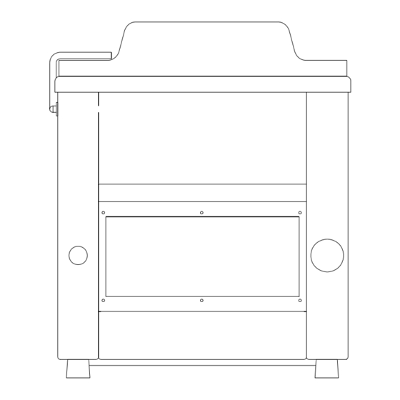
Page 26: Body Diagram
7.1 BODY DIAGRAM Body Diagram TC28100000... - Page 27 TC28100P00(P) PART NO. DESCRIPTION Q'TY NOTE TC28101002 Frame TC28102003 Back door ETC28F0061110 Box, Electric VA04120001 Vibration absorber foot TC28130001 VA04132000 Washer 2705152 Flat washer M8 (S) 2705301 Split lock washer M8 (S) 2874051 Control panel PD-01 10 28704940 Button guard ZBP0 11 29135561 Vacuum gauge 1-1/2x760mm 12 29090426...
-
Page 28: Vacuum Chamber Diagram
7.2 VACUUM CHAMBER DIAGRAM Vacuum Chamber Diagram TC28200000... - Page 29 TC28200P00 PART NO. DESCRIPTION Q'TY NOTE TC28201001 Vacuum chamber TC28210000 Hex busing block holder TC28211000 Hex busing block holder 2740168 O-ring 2740169 O-ring TC28212000 Sealing bar plate 2703308 Round head screw M4 x 12 (S) VA04213000 Sealing bar holder 2705150 Flat washer M5 (S) 10 2705303 Split lock washer M5 (S)
- Page 30 TC28200P01 PART NO. DESCRIPTION Q'TY NOTE 36 2702090 Screw, flat philip M4x10 (S) 37 29090429 Fitting, L TYPE A-015-1 1/4”x5/16" 38 2909155 Fitting, P-108 1/4” 39 29093251 Nipple 1/4"x2"...
-
Page 31: Seal Bar Configuations
7.3.1 SEALING BAR-STANDARD DIAGRAM ( F ) Sealing Bar-Standard Diagram TC28270A00... - Page 32 TC28270P00 PART NO. DESCRIPTION Q'TY NOTE TC28270000 Sealing bar (F) VA04271000 Sealing wire holder 3200955 Teflon tape, 40mm 2827010064 Sealing wire VA04277000 Spring 3900958 Teflon tape, 16mm 2703304 Screw, round hd M4x6 (S) 2704617 Socket set screw M4x10 (S) TC28231000 Teflon tap clamp...
-
Page 33: Seal Bar Diagram(Fc)
7.3.2 SEALING BAR-STANDARD DIAGRAM ( FC ) Sealing Bar-Standard Diagram TC28220A00... - Page 34 TC28220P00 PART NO. DESCRIPTION Q'TY NOTE TC28220000 Sealing bar VA04221000 Sealing wire holder 3200955 Teflon tape 40mm 2824050265 Sealing wire 2827130012 Cutting wire 2704617 Socket set screw M4 x 10 3200961 Teflon tape 2703304 Round head screw M4 x 6 TC28231000 Teflon tap clamp...
-
Page 35: Lid Diagram
7.4 LID DIAGRAM Lid Diagram TC28300000... - Page 36 TC28300P00 PART NO. DESCRIPTION NOTE TC28301001 Vacuum lid 3114459 Lid gasket VA04303001 Binding post screw 3200409 Fitting Carton TC28311001 Cushion bar 3114463 Sealing silicone(F) TC28320000 Lid holder TC28321001 Hinge pin TC28322001 Hinge bolt 10 VA04330001 Gas spring 11 TC28325000 Washer 12 2700462 Hex head screw M6 x 30 13 2705151...
-
Page 37: Electrical Box
7.5 ELECTRICAL BOX ITEM PART NO. DESCRIPTION SPECIFICATION Q’TY NOTE 2810739 Contactor 3A1a CN-11-B5 (AC24V) 2810758 Contactor CU-18/4P-4A (AC24V) 1ψ 2811534 Overload Relay RHU-10K1(4.5~6.3A) 110V DVP06 2890048 Fuse 20mm 1A 2890063 Fuse 20mm 4A 2890068 Fuse (F) 20mm 15A Option 2890069 Fuse (FC) 20mm 25A...
Need help?
Do you have a question about the TC-280 and is the answer not in the manual?
Questions and answers