Table of Contents
Advertisement
Quick Links
Advertisement
Table of Contents

Related Manuals for BOCK HA44e


Summary of Contents for BOCK HA44e
- Page 1 BOCK HA 44 e (LG) Assembly instructions 96418-06.2021-Gb Translation of the original instructions HA44e/475-4 HAX44e/475-4 HA44e/565-4 HAX44e/565-4 HA44e/665-4 HAX44e/665-4 HAX44e/475 LT 9 LG HAX44e/565 LT 12 LG HAX44e/665 LT 14 LG BOCK ® colour the world of tomorrow...
-
Page 2: Table Of Contents
About these instructions Read these instructions before assembly and before using the compressor. This will avoid misunder- standings and prevent damage. Improper assembly and use of the compressor can result in serious or fatal injury. Observe the safety instructions contained in these instructions. These instructions must be passed onto the end customer along with the unit in which the compres- sor is installed. Manufacturer Bock GmbH 72636 Frickenhausen Contact Bock GmbH Benzstraße 7 72636 Frickenhausen Germany Phone +49 7022 9454-0 Fax +49 7022 9454-137 www.bock.de service@bock.de Contents Page Safety 1.1 Identification of safety instructions 1.2 Qualifications required of personnel 1.3 General safety instructions 1.4 Intended use Safety instructions for use of flammable refrigerants 2.1 Safety instructions 2.2 Qualifications required of personnel Product description 3.1 Short description... - Page 3 Contents Page Areas of application at LG compressors 5.1 Refrigerants 5.2 Oil charge 5.3 Limits of application Compressor assembly 6.1 Storage and transport 6.2 Setting up 6.3 Pipe connections 6.4 Pipes 6.5 Laying suction ans pressure lines 6.6 Operating the shut-off valves 6.7 Operating mode of the lockable service connections 6.8 Suction pipe filter and filter drier Electrical connection 7.1 Information for contactor and motor contactor selection 7.2 Standard motor, design for direct or partial winding start 7.3 Basic circuit diagram for partial winding start with standard motor 7.4 Special motor: design for direct or star-delta start 7.5 Basic circuit diagram for star-delta start with special motor 7.6 Electronic trigger unit INT69 G 7.7 Connecting of the trigger unit INT69 G 7.8 Functional test of the trigger unit INT69 G 7.9 Electronic trigger unit INT69 G on LG compressors 7.10 Oil sump heater (accessories)
-
Page 4: Safety
1| Safety 1.1 Identification of safety instructions: DANGER Indicates a dangerous situation which, if not avoided, will cause immediate fatal or serious injury. WARNING Indicates a dangerous situation which, if not avoided, may cause fatal or serious injury. CAUTION Indicates a dangerous situation which, if not avoided, may cause fairly severe or minor injury. ATTENTION Indicates a situation which, if not avoided, may cause property damage. INFO Important information or tips on simplifying work. 1.2 Qualifications required of personnel WARNING Inadequately qualified personnel poses the risk of accidents, the consequence being serious or fatal injury. Work on compressors is therefore reserved for personnel which is qualified to work on pressurized refrigerant systems: • F or example, a refrigeration technician, refrigeration mechatronic engineer. As well as professions with comparable training, which enables personnel to assemble, install, maintain and repair refrigeration and air-conditioning systems. Personnel must be capable of assessing the work to be carried out and recognising any potential... -
Page 5: General Safety Instructions
The compressor may not be used in potentially explosive environments! These assembly instructions describe the standard version of the compressor named in the title manufactured by Bock. Bock refrigerating compressors are intended for installation in a machine (within the EU according to the EU Directives 2006/42/EC Machinery Directive, 2014/68/EU Pressure Equipment Directive). Commissioning is permissible only if the compressor has been installed in accordance with these as- sembly instructions and the entire system into which it is integrated has been inspected and approved in accordance with legal regulations. -
Page 6: Safety Instructions For Use Of Flammable Refrigerants
2 | Safety instructions for use of flammable refrigerants 2.1 Safety instructions DANGER • Explosion and fire risk! Synthetic HFO refrigerants are colourless, combustible gases which occur naturally and which are explosive in a certain blend! • HFO refrigerants are classified into the safety group A2L (hardly- inflammable refrigerant) according to EN 378. As they are heavier than air, the operating location must be above ground level to allow unrestricted discharge of the gas. •... -
Page 7: Product Description
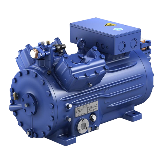
3| Product description 3.1 Short description • Semi-hermetic four-cylinder reciprocating compressor with oil pump lubrication. • Flange-mounted drive motor on the compressor case. • Specially or deep cooling with air-cooled motor and direct suction at the cylinder. Terminal box Discharge Transport shut-off valve eyelet Valve plate Cylinder cover Oil pump Name plate Oil sight glass Fig. 1 Suction shutoff valve Air guide hood with fan Fig. 2 Dimension and connection values can be found in Chapter 12. -
Page 8: Type Key
3| Product description 3.2 Name plate (example) BOCK Bock GmbH, Benzstr. 7 72636 Frickenhausen, Germany HA44e/665-4 57,7 AZ12345A001 20,3 A 19,7 A 69,2 101 A 174 A BOCK lub E55 IP44 SE 55 Fig. 3 Type designation Voltage, circuit, frequency 50 Hz Machine number Nominal rotation speed maximum operating current Displacement Starting current (rotor blocked) Voltage, circuit, frequency... - Page 9 3| Product description 3.4 Typ key LG compressor (example) LT 9 4 e 475 Low-GWP Engine performance in hp Engine for deep-freezing Swept volume e-series Numbers of cylinders Size Oil charge ² Series ¹ ¹ HA - Hermetic Air-cooled for deep-freezing ² X - Ester oil charge...
-
Page 10: Areas Of Application
4 | Areas of application 4 .1 Refrigerants • HFKW / HFC: R404A/R507 • (H)FCKW / (H)CFC: 4.2 Oil charge The compressors are filled at the factory with the following oil type: - for R404A/R507 BOCK lub E55 BOCK lub A 46 - for R22 Compressors with ester oil charge ( BOCK lub E55 ) are marked with an X in the type designation (e.g. HAX34e/315-4). INFO For refilling, we recommend the above oil types. Alternatives: see chapter 9.4 ATTENTION The oil level must be in the max. visible part of the sight glass; 1,6 Ltr. oil level damage to the compressor is possible if overfilled or min. -
Page 11: Limits Of Application
R455A, R454C 5.2 Oil charge The compressors are factory-charged with the following oil type: LG Compressors: BOCK lub E55 5.3 Limits of application ATTENTION Compressor operation is possible within the operating limits. These can be found in Bock compressor selection tool (VAP) under vap.bock.de. Observe the information given there and the follo- wing notes: - Min. pressure gas temperature ≥ 50°C (min. 20K over condens- ing temperature). Suction gas superheating on compressor ent- rance should be min. 7 - 10 K, must be increased if necessary - Min. oil temperature ≥ 30°C. - Operation in the vacuum range is not permitted. During operation in the vacuum range, there is a danger of air entering on the suction side. This can cause chemical reactions,... -
Page 12: Compressor Assembly
6| Compressor assembly INFO New compressors are factory-filled with inert gas. Leave this ser- vice charge in the compressor for as long as possible and prevent the ingress of air. Check the compressor for transport damage before starting any work. 6.1 Storage and transport Storage at (-30°C) - (+70°C), maximum permissible relative humidity 10% - 95%, no condensation Do not store in a corrosive, dusty, vaporous atmosphere or in a com- bustible environment. Use transport eyelet. Do not lift manually! Use lifting gear! 6.2 Setting up ATTENTION Attachments (e.g. pipe holders, additional units, fastening parts, etc.) directly to the compressor are not permissible! Provide adequate clearance for maintenance work. Ensure adequate compressor ventilation. The compressor must not be in the air stream to another component of the refrigeration system (e.g. condenser). The cooling of the drive motor must be reliable guaranteed. Do not use in a corrosive, dusty, damp atmosphere or a combustible environment. Setup on an even surface or frame with sufficient load- bearing capacity. -
Page 13: Pipe Connections
6| Compressor assembly 6.3 Pipe connections ATTENTION Damage possible. Superheating can damage the valve. Remove the pipe supports from the valve for soldering. Only solder using inert gas to inhibit oxidation products (scale). The pipe connections have graduated inside diameters so that pipes with standart millimetre and inch dimensions can be used. T he connection diameters of the shut-off valves are rated for maximum compressor output. The actual required pipe cross section must be matched to the output. The same applies for non-return valves. Fig. 5: graduated internal diameter 6.4 Pipes Pipes and system components must be clean and dry inside and free of scale, swarf and layers of rust and phosphate. Only use air-tight parts. Lay pipes correctly. Suitable vibration compensators must be provided to prevent pipes being cracked and broken by severe vibrations. Ensure a proper oil return. Keep pressure losses to an absolute minimum. 6.5 Laying suction and pressure lines ATTENTION Improperly installed pipes can cause cracks and tears, the result being a loss of refrigerant. -
Page 14: Operating The Shut-Off Valves
6| Compressor assembly A rule of thumb: Always lay the first pipe section starting from the shut-off valve downwards and parallel to the drive shaft. Rigid fixed point As short as Fig. 6 possible 6.6 Operating the shut-off valves Before opening or closing the shut-off valve, release the valve spindle seal by approx. ¼ of a turn counter-clockwise. After activating the shut-off valve, re-tighten the adjustable valve spindle seal clockwise. Tighten Release Valve spindle seal Fig. 7 Fig. 8... -
Page 15: Operating Mode Of The Lockable Service Connections
6| Compressor assembly 6.7 Operating mode of the lockable service connections Connection cannot Service connection be shut off closed Pipe connection Connection Spindle blocked Fig. 9 Opening the shut-off valve: Compressor Spindle: turn to the left (counter-clockwise) as far as it will go. —> Shut-off valve completely opened / service connection closed. The connection which cannot be shut off is intended for safety devices. Connection cannot Service connection be shut off opened Pipe connection Connection Spindle open Fig. 10 Opening the service connection Compressor Spindle: Turn ½ - 1 turn to the right clockwise. —> Service connection opened / shut-off valve opened. The connection which cannot be shut off is intended for safety devices. After activating the spindle, generally fit the spindle protection cap again and tighten with 14-16 Nm. This serves as a second sealing feature during operation. 6.8 Suction pipe filter and filter drier For systems with long pipes and higher degree of contamination, a filter on the suction-side is recommended. The filter has to be be renewed depending on the degree of contamination (reduced pressure loss). -
Page 16: Electrical Connection
7| Electrical connection Electrical connection DANGER Risk of electric shock! High voltage! Only carry out work when the electrical system is disconnected from the power supply! ATTENTION When attaching accessories with an electrical cable, a minimum bending radius of 3 x the cable diameter must be maintained for laying the cable. INFO Connect the compressor motor in accordance with the circuit diagram (see inside of terminal box). Use suitable cable entry point of the correct protection type (see name plate) for routing cables into the terminal box. Insert the strain reliefs and prevent chafe marks on the cables. Compare the voltage and frequency values with the data for the mains power supply. Only connect the motor if these values are the same. 7.1 Information for contactor and motor contactor selection All protection equipment, switching and monitoring devices must comply with the local safety regula- tions and established specifications (e.g. VDE) and regulations as well as the manufacturer’s speci- fications. Motor protection switches are required! Motor contactors, feed lines, fuses and motor protection switches must be rated according to the maximum operating current (see name plate). For motor protection, use a current-independent, time-delayed overload protection device for monitor- ing all three phases. Adjust the overload protection device so that it must be actuated within 2 hours at 1.2 times the maximum working current. -
Page 17: Standard Motor, Design For Direct Or Partial Winding Start
7| Electrical connection 7.2 Standard motor, design for direct or partial winding start Designation on the name plate Y/YY Compressors with this marking are suitable for direct or partial winding start. The motor winding is subdivided into two parts: Part winding 1 = 50% and part winding 2 = 50%. This winding division reduces the start-up current needed for a part winding start to approx. 50% of that for a direct start. INFO A mechanical unloaded start with bypass solenoid valve is not required. -
Page 18: Basic Circuit Diagram For Partial Winding Start With Standard Motor
7.3 Basic circuit diagram for partial winding start with standard motor FC1.1 FC1.2 FC1.1 I> I> I> I> I> I> I> I> I> FC1.1 FC1.1 FC1.2 FC1.2 FC1.2 I> I> I> L3 N PE L3 N PE ˜ Y/YY B1 B2 B1 B2 INT69 INT69G Compressor terminal box Anschlußkasten Verdichter Anschlußkasten Verdichter Fig. 11 High pressure safety monitor Safety chain (high/low pressure monitoring ) - Page 19 L1.1 L2.1 L3.1 L1.2 P> Θ DANGER Explosion risk! Θ Electronic trigger INT69 G at LG compressors has to be installed outside any Θ DELTA- P II danger area! See also chapter 7.9. Θ FC1.1/1.2 Motor protection switch Control power circuit fuse Fan motor INT69 G Electronic trigger unit INT69 G Delay relay for contactor switchover Main switch PW INT69 HA44 neu Mains contactor (part winding 1) BOCK COMPRESSORS Mains contactor (part winding 2) Control voltage switch...
- Page 20 7| Electrical connection The motor is wired for direct start (YY) at the factory. For part winding start Y / YY, the bridges must be removed and the motor feed line connected according to the circuit diagram: 400 V Direktstart YY Teilwicklungsstart Y/YY Direct start YY Part winding start Y/YY ATTENTION Failure to do this results in opposed rotary fields and results in damage to the motor. After the motor starts up via partial winding 1, partial winding 2 must be switched on after a maximum delay of one second . Failure to comply can adversely affect the service life of the motor.
-
Page 21: Special Motor: Design For Direct Or Star-Delta Start
7| Electrical connection 5.4 Sondermotor: Ausführung für Direkt- oder Stern-Dreieck-Anlauf 5.4 Sondermotor: Ausführung für Direkt- oder Stern-Dreieck-Anlauf 5.4 Sondermotor: Ausführung für Direkt- oder Stern-Dreieck-Anlauf 7.4 Special motor: design for direct or star-delta start Für den Stern-Dreieck-Anlauf ist eine mechanische Anlaufentlastung mit Bypass-Magnetventil Für den Stern-Dreieck-Anlauf ist eine mechanische Anlaufentlastung mit Bypass-Magnetventil Für den Stern-Dreieck-Anlauf ist eine mechanische Anlaufentlastung mit Bypass-Magnetventil A mechanical unloaded start with bypass solenoid valve (accessories) is required for the (Zubehör) erforderlich. -
Page 22: Basic Circuit Diagram For Star-Delta Start With Special Motor
7.5 Basic circuit diagram for star-delta start with special motor FC1.1 I> I> I> FC1.1 FC1.2 FC1.2 I> I> I> L3 N PE ˜ B1 B2 INT69G Compressor terminal box Anschlußkasten Verdichter Fig. 12 High pressure safety monitor Safety chain (high/low pressure monitoring ) Cold conductor (PTC sensor) motor winding Thermal protection thermostat (PTC sensor) Oil temperature sensor Release switch (thermostat) Datum 20.02.2009 DELTA PII Oil differential pressure sensor DELTA-P II (accessories) Bearb. bauknecht Gepr. 26.11.2020 Oil sump heater Οnderung Datum Name... - Page 23 L1.1 L2.1 L3.1 L1.2 P> Θ DANGER Explosion risk! Θ Electronic trigger INT69 G at LG compressors has to Θ be installed outside any danger area! See also chapter 7.9. DELTA- P II Θ Control power circuit fuse Fan motor INT69 G Electronic trigger unit INT69 G Delay relay for contactor switchover Main switch Mains contactor D/S INT69 HA44 neu Δ-contactor BOCK COMPRESSORS Y-contactor Control voltage switch...
-
Page 24: Electronic Trigger Unit Int69 G
7| Electrical connection 7.6 Electronic trigger unit INT69 G The compressor motor is fitted with cold conductor temperature sensors (PTC) connected to the electronic trigger unit INT69 G in the terminal box. In case of excess temperature in the motor winding, the INT69 G deactivates the motor contactor. Once cooled, it can be restarted only if the electronic lock of the output relay (terminals B1+B2) is released by interrupting the supply voltage. The hot gas side of the compressor can also be protected against overtemperature using thermal protection thermostats (accessory). The unit trips when an overload or inadmissible operating conditions occur. Find and remedy the cause. - Page 25 7| Electrical connection 7.8 Function test of the trigger unit INT69 G Before commissioning, after troubleshooting or making changes to the control power circuit, check the functionality of the trigger unit. Perform this check using a continuity tester or gauge. Relay position INT69 G Gauge state Relay position Deactivated state 11-12 INT69 G switch-on 11-14 B2 12 14 11 Remove PTC connector 11-12 Fig. 14 Insert PTC connector 11-12 Reset after mains on 11-14 7.9 Electronic trigger unit INT69 G at LG compressors The supplied INT69 G must be connected according to the wiring diagram shown here in a separate control cabinet, which must be installed outside each danger zone. ATTENTION Install heat protection thermostats and cold conductor motor winding in series! Schaltschrank Switch cabinet Schaltschrank INT69G INT69G Cold conductor (PTC 10 11 12 13 20 21 sensor) motor winding 10 11 12...
-
Page 26: Oil Sump Heater (Accessories)
7| Electrical connection 7.10 Oil sump heater (accessories) When the compressor is at a standstill, refrigerant diffuses into the lubricating oil of the compressors housing, depending on pressure and ambient temperature. This reduces the lubricating capacity of the oil. When the compressor starts up, the refrigerant contained in the oil evaporates out throught the reduction in pressure. The consequences can be foaming and migration of the oil, causing oil shocks under certain circumstances. Operation: The oil sump heater operates when the compressor is at a standstill. When the compres- sor starts up, the oil sump heater switches off again automatically. Connection: The oil sump heater must be connected via an auxiliary contact (or parallel wired auxili- Anschlussschema für Ölsumpfheizung ary contact) of the compressor contactor to a seperate electric circuit. Connection diagramm for oil sump heater El. data: 230 V - 1 - 50/60 Hz, 160 W. Plan de raccordement pour résistance de carter d‘huile Fig. 16 ATTENTION Connection to the current path of the safety control chain is not permitted. -
Page 27: Oil Sump Heater On Lg Compressors
7 | Electrical connection 7.11 Oil sump heater on LG compressors As the solubility of HFO refrigerants in oil can be very high, especially at high suction pressures, the compressor must be equipped with an oil sump heater. For this reason, a pump-down circuit is recommended during standstill to reduce the suction-side standstill pressures. Electrical data: 230 V - 1 - 50/60 Hz, 160 W. ATTENTION The oil sump heater must generally be connected and operated! • In a TT- or TN system, a residual current protection device (RCD) must be used. • In an IT system, an insulation monitoring device must be used. National standards and regulations must be observed. 7.12 Capacity regulator (Accessories) ATTENTION A fuse (max. 3xlB in accordance with IEC 60127-2-1) corresponding to the rated current must be placed in front of every magnetic coil of the capacity regulator as short-circuit protection. The ra- ted voltage of the fuse must be equal to or greater than the rated voltage of the magnetic coil. The ability of the fuses to switch off... -
Page 28: Commissioning
8| Commissioning 8.1 Preparations for start-up INFO To protect the compressor against inadmissible operating conditions, high pressure and low pressure pressostats are mandatory on the installation side. The compressor has undergone trials in the factory and all functions have been tested. There are therefore no special running-in instructions. Check the compressor for transport damage! 8.2 Pressure integrity test The compressor has been tested in the factory for pressure integrity. If however the entire system is to be subjected to a pressure integrity test, this should be carried out in accordance with EN 378-2 or a corresponding safety standard without the inclusion of the compressor. 8.3 Leak test DANGER Risk of bursting! The compressor must only be pressurised using nitrogen (N Never pressurise with oxygen or other gases! The maximum permissible overpressure of the compressor must not be exceeded at any time during the testing process (see name plate data)! Do not mix any refrigerant with the nitrogen as this could cause the ignition limit to shift into the critical range. -
Page 29: Refrigerant Charge
8| Commissioning 8.5 Refrigerant charge CAUTION Wear personal protective clothing such as goggles and protective gloves! Make sure that the suction and pressure line shut-off valves are open. With the compressor switched off, add the liquid refrigerant directly to the condenser or receiver, breaking the vacuum. If the refrigerant needs topping up after starting the compressor, it can be topped up in vapour form on the suction side, or, taking suitable precautions, also in liquid form at the inlet to the evaporator. ATTENTION Avoid overfilling the system with refrigerant! To avoid shifts in concentration, zeotropic refrigerant blends must always only be filled into the refrigerating plant in liquid form. Do not pour liquid coolant through the suction line valve on the compressor. It is not permissible to mix additives with the oil and refrigerant. 8.6 Start-up WARNING Ensure that both shut-off valves are open before starting the compressor! Check that the safety and protection devices (pressure switch, motor protection, electrical contact protection measures, etc.) are all functioning properly. Switch on the compressor and allow to run for a minimum of 10 min. Check the oil level by: The oil must be visible in the sightglass. ATTENTION I f larger quantities of oil have to be topped up, there is a risk of oil hammer effects. If this is the case check the oil return! -
Page 30: Connection Of Oil Level Regulator
8| Commissioning 8.7 Avoiding slugging ATTENTION Slugging can damage the compressor and cause refrigerant to leak. To prevent slugging: The complete refrigeration system must be properly designed. All components must be compatibly rated with each other with regard to output (particularly the evaporator and expansion valves). Suction gas superheat at the compressor input should be min. 7 - 10 K. (check the setting of the expansion valve). For LG compressors see chapter 5.3. The system must reach a state of equilibrium. Particularly in critical systems (e.g. several evaporator points), measures are recommended such as replacement of liquid traps, solenoid valve in the liquid line, etc. There should be no movement of coolant whatsoever while the compressor is at a standstill. 8.8 Connection of oil level regulator Oil level regulation systems have proven themselves with parallel circuits of several compressors. The connection "0" is provided for installing an oil level regulator (see dimensions drawing). All common oil level regulators from AC&R, ESK and Carly as well as the OM3 TraxOil oil level regulation system from Alco can be connected directly without adapters (see Fig. 17). A sight glass on the oil level regulator is not required. Anschluss Ölspiegelregulator Bei Verbundschaltungen von mehreren Verdichtern haben sich Ölstandsregulierungssysteme bewährt. Für die Montage eines Ölspie- M6 x 10 gelregulators ist der Anschluss „O“... -
Page 31: Maintenance
200 operating hours, then approx. every 3 years or 10,000 - 12,000 operating hours. Dispose of used oil according to the regulations; observe national regulations. Annual checks: Oil level, leak tightness, running noises, pressures, temperatures, function of a uxiliary devices such as oil sump heater, pressure switch. 9.3 Spare parts recommendation/accessories Available spare parts and accessories can be found on our compressor selection tool under vap.bock.de as well as at bockshop.bock.de. Only use genuine Bock spare parts! -
Page 32: Lubricants / Oil
The oil type filled as standard in the factory is marked on the name plate, and this should always be used, even in the case of maintenance units. Alternative oil types can vary significantly in quality due to additives or inferior raw materials by the manufacturer. Validation within the compressors entire operating limits can not be guaranteed, if such alternative oil types are used. It is for this reason, that we only recommend the use of oil from Bock! Bock assumes no liability for any damage arising from alternative oil types. Refrigerants Bock standard oil types BOCK lub E55 (e.g. R134a, R407C) BOCK lub E55 HFO (e.g. R455A, R454C)) BOCK lub A46 HCFC (e.g. R22) 9.5 Decommissioning Close the shut-off valves on the compressor. Drain the refrigerant (it must not be discharged into the environment) and dispose of it according to the regulations. When the compressor is depressurised, undo the fastening screws of the shut-off valves. Remove the compressor using an appropriate hoist. Dispose of the oil inside in accordance with the applicable national regulations. 9.6 Additional information when using flammable refrigerants WARNING • During maintenance and repair, it must be noted that HFO refrigerants residues may dissolve in the oil. Therefore, electrical tests must not be conducted while oil remains in the compressor. • If the compressor is to be removed from the system for maintenance or repair, the remaining refrigerant must be suctioned out and the compressor evacuated. The compressor... -
Page 33: Accessories
10| Accessories 10.1 Capacity regulator ATTENTION If the capacity regulator is installed at the factory, it is subsequently installed and connected by the customer. LR 1 Fig. 19 Delivery condition 1 (from the factory): Fig. 18 Cylinder cover prepared for capacity regulator. Fig. 20 Fig. 21 Delivery condition 2 (from the factory): Before commissioning, the blind flange with Connect capacity regulator in terminal box or screws must be removed and replaced by the switch cabinet. new set capacity regulator with O-ring joints and screws. Observe position and construction of the capacity regulator. Attention! Compressor is under pressure! Depressurize the compressor first. WARNING Several capacity regulators cannot switch at the same time during compressor operation! Otherwise the sudden change in load can damage the compressor! Comply with the switching interval of 60 s. - Page 34 10| Accessories ATTENTION Capacity-regulated operation alters the gas speeds and pressure r atios of the refrigerating plant: Adjust the suction line routing and dimensioning accordingly, do not set the control intervals too close and do not let the system switch more than 12 times per hour (refrigerating plant must have reached a state of equilibrium). Continuous operation in the control stage is not recommended as the gas velocity in the plant system under certain circumstances does not guarantee sufficient oil return to the compressor with activated capacity regulator. W e recommend switching to unregulated operation (100% capac- ity) for at least 5 minutes per capacity-regulated operating hour. An assured oil return can also be realised by a 100% capacity requirement after each compressor restart. E lectrical actuation of the solenoid valve: Normally open, (cor- responds to 100 % compressor capacity). Special accessories are only premounted in the factory if ordered specially by customer. Retrofitting is possible in full compliance with the safety instructions and repair instructions enclosed with the kits. Information about the use, operation, maintenance and servicing of the components is available in the printed literature or on the internet under www.bock.de. For the capacity regulator a step protection is optional available, Art-Nr. 81449. Fig. 22...
-
Page 35: Technical Data
11| Technical data Oil charge (sight glass centre) Oil charge (ex works) Suction line Discharge line Weight Starting current (rotor locked) Max. power consumption Max. operating current 380-420 V Y/YY - 3 - 50 Hz PW 440-480 V Y/YY - 3 - 60 Hz PW Voltage PW = Part Winding Winding ratio : 50 % / 50 % Displacement (1450 / 1740 rpm) No. of cylinders Type*... -
Page 36: Dimensions And Connections
09.05.19 09.05.19 V. Polizzi V. Polizzi A. Layh A. Layh GEA Bock GmbH - Benzstraße 7 - 72636 Frickenhausen - Germany - www.bock.de Freigabe / Approve Maß / Dimension Passung / Clearance Änd.-Nr. / Mod-No. Datum / Date Bearb. / Edited Geprüft / Appr. -
Page 37: Declaration Of Incorporation
13 | Declaration of incorporation Declaration of incorporation for incomplete machinery in accordance with EC Machinery Directive 2006/42/EC, Annex II 1. B Manufacturer: Bock GmbH Benzstraße 7 72636 Frickenhausen, Germany We, as manufacturer, declare in sole responsibility that the incomplete machinery... -
Page 38: Service
14| Service Dear customer, if you have any questions about installation, operation and accessories, please contact our technical service or specialist wholesaler and/or our representative. The Bock service team can be contacted by phone, +49 (0)7022 9454-0 or via service@bock.de Yours faithfully Bock GmbH... - Page 40 BOCK ® Bock GmbH Benzstraße 7 72636 Frickenhausen Germany Phone +49 7022 9454-0 +49 7022 9454-137 www.bock.de © Bock GmbH. All rights reserved. Subject to modifications. Printed in Germany.
Need help?
Do you have a question about the HA44e and is the answer not in the manual?
Questions and answers