Table of Contents

Related Manuals for BOCK HGX22e A Series


Summary of Contents for BOCK HGX22e A Series
- Page 1 BOCK HGX Assembly instructions 96192-01.2021-Gb Translation of the original instructions HGX22e/125-4 A HGX22e/125-4 S A HGX22e/160-4 A HGX22e/160-4 S A HGX22e/190-4 A HGX22e/190-4 S A BOCK ® colour the world of tomorrow...
- Page 2 Observe the safety instructions contained in these instructions. These instructions must be passed onto the end customer along with the unit in which the compres- sor is installed. Manufacturer Bock GmbH 72636 Frickenhausen Contact Bock GmbH Benzstraße 7...
-
Page 3: Table Of Contents
Contents Page Safety 1.1 Identification of safety instructions 1.2 Qualifications required of personnel 1.3 General safety instructions 1.4 Intended use Product description 2.1 Short description 2.2 Name plate 2.3 Type key Areas of application 3.1 Refrigerants 3.2 Oil charge 3.3 Limits of application Compressor assembly 4.1 Storage and transport 4.2 Setting up 4.3 Maximum permissible inclination 4.4 Pipe connections... -
Page 4: Safety
1| Safety 1.1 Identification of safety instructions: DANGER Indicates a dangerous situation which, if not avoided, will cause immediate fatal or serious injury. WARNING Indicates a dangerous situation which, if not avoided, may cause fatal or serious injury. CAUTION Indicates a dangerous situation which, if not avoided, may cause fairly severe or minor injury. -
Page 5: General Safety Instructions
These assembly instructions describe the standard version of the compressor named in the title manufactured by Bock. Bock refrigerating compressors are intended for installation in a machine (within the EU according to the EU Directives 2006/42/EC Machinery Directive and 2014/68/EU Pres- sure Equipment Directive). -
Page 6: Product Description
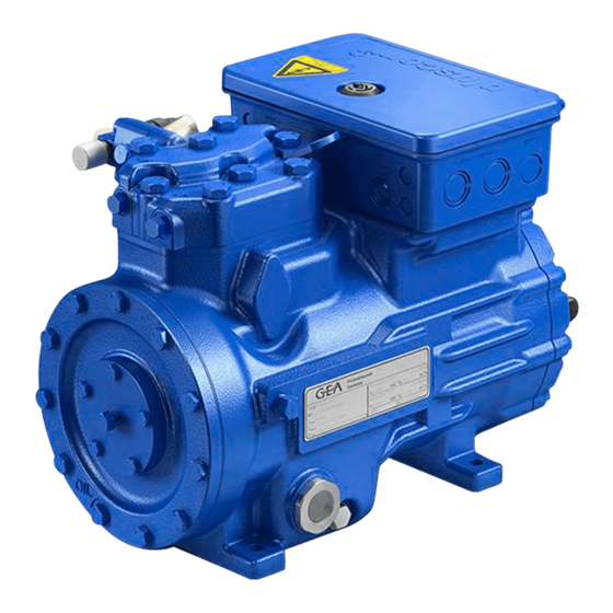
2| Product description 2.1 Short description • Semi-hermetic two-cylinder reciprocating compressor with oil pump lubrication. • Lightweight aluminum design • Suction gas cooled drive motor Transport eyelet Discharge shut- off valve Name plate Oil pump Oil sight glass Fig. 1 Cylinder cover Terminal box Valve plate... -
Page 7: Type Key
2| Product description Typschild (Beispiel) 2.2 Name plate (example) BOCK Bock GmbH, Benzstr. 7 72636 Frickenhausen, Germany HGX22e/190-4 S A AS35830A001 16,2/9,4A SE 55 Fig. 3 Typbezeichnung Spannung, Schaltung, Frequenz Type designation Voltage, circuit, frequency 50 Hz Maschinennummer Nenndrehzahl 50 Hz Machine number Nominal rotation speed... -
Page 8: Areas Of Application
3.3 Limits of application ATTENTION! Compressor operation is possible within the operating limits. These can be found in Bock compressor selection tool (VAP) under vap.bock.de. Observe the information given there. - Permissible ambient temperature (-20°C) - (+60°C) - Max. permissible discharge end temperature 140°C. - Page 9 ATTENTION! When operating in the vacuum range, there is a danger of air entering on the suction side. This can cause chemical reactions, a pressure rise in the condenser and an elevated compressed- gas temperature. Prevent the ingress of air at all costs! LP = Low pressure Max.
-
Page 10: Compressor Assembly
4 | Compressor assembly INFO New compressors are factory-filled with inert gas. Leave this ser- vice charge in the compressor for as long as possible and prevent the ingress of air. Check the compressor for transport damage before starting any work. 4.1 Storage and transport Storage at (-30°C) - (+70°C), maximum permissible relative humidity 10% - 95%, no condensation Do not store in a corrosive, dusty, vaporous atmosphere or in a com- bustible environment. -
Page 11: Maximum Permissible Inclination
4 | Compressor assembly 4.3 Maximum permissible inclination ATTENTION! Poor lubrication can damage the compressor. Respect the stated values. max. 30°, max. 2 minutes max. 15°, continuous operation Fig. 10 4.4 Pipe connections The discharge and suction line valves have stepped internal diameters so that pipes with standard millimetre and inch dimensions can be used. -
Page 12: Pipes
4 | Compressor assembly 4.5 Pipes Pipes and system components must be clean and dry inside and free of scale, swarf and layers of rust and phosphate. Only use air-tight parts. Lay pipes correctly. Suitable vibration compensators must be provided to prevent pipes being cracked and broken by severe vibrations. -
Page 13: Operating Mode Of The Lockable Service Connections
4 | Compressor assembly 4.8 Operating mode of the lockable service connections Service connec- tion closed Pipe connection Spindle Connection blocked Compressor Fig. 15 Opening the shut-off valve: Spindle: turn to the left (counter-clockwise) as far as it will go. —> Shut-off valve completely opened / service connection closed. Service connec- tion opened Pipe connection Connection... -
Page 14: Electrical Connection
5| Electrical connection Electrical connection DANGER! High voltage! Risk of electric shock! Only carry out work when the electrical system is disconnected from the power supply! ATTENTION! When attaching accessories with an electrical cable, a minimum bending radius of 3 x the cable diameter must be maintained for laying the cable. -
Page 15: Connection Of The Driving Motor
5| Electrical connection 5.2 Connection of the driving motor The compressor is designed with a motor for star-delta circuits. Designation on the name plate ∆ / Y Star-delta start-up is only possible in the ∆ voltage range. Example: 230 V ∆ 400 V Y L1 L2 Direct start... - Page 16 5.3 Circuit diagram for direct start 230 V ∆ / 400 V Y FC1.1 I> I> I> FC1.1 L3 N PE -EC1 Θ B1 B2 INT69G Compressor terminal box Anschlußkasten Verdichter Fig. 17 Cold conductor (PTC sensor) motor winding Thermal protection thermostat (PTC sensor) Load circuit safety switches Control power circuit fuse High pressure safety monitor Safety chain (high/low pressure monitoring ) Release switch (thermostat)
- Page 17 L1.1 L2.1 L3.1 L1.2 P> Θ Θ Main switch Control voltage switch Compressor motor Compressor contactor INT69 G Electronic trigger unit INT69 G Oil sump heater...
-
Page 18: Electronic Trigger Unit Int69 G
5| Electrical connection 5.4 Electronic trigger unit INT69 G The compressor motor is fitted with cold conductor temperature sensors (PTC) connected to the electronic trigger unit INT69 G in the terminal box. In case of excess temperature in the motor winding, the INT69 G deactivates the motor contactor. -
Page 19: External Connection Int69 G
5 | Electrical connection 5.6 External connection INT69 G Schaltschrank Schaltschrank Switch cabinet INT69G INT69G Cold conductor (PTC sensor) motor winding 8 09 10 11 12 Heat protection thermo- 8 09 10 11 12 stat (PTC sensor) Oil sump heater Terminal box Fig. 19 5.7 Function test of the trigger unit INT69 G Before commissioning, after troubleshooting or making changes to the control power circuit, check the functionality of the trigger unit. -
Page 20: Commissioning
6| Commissioning 6.1 Preparations for start-up INFO! To protect the compressor against inadmissible operating conditions, high pressure and low pressure pressostats are mandatory on the installation side. The compressor has undergone trials in the factory and all functions have been tested. There are therefore no special running-in instructions. -
Page 21: Refrigerant Charge
6 | Commissioning 6.5 Refrigerant charge CAUTION! Wear personal protective clothing such as goggles and protective gloves! Make sure that the suction and discharge line valves are open. With the compressor switched off, add the liquid refrigerant directly to the condenser or receiver, breaking the vacuum. If the refrigerant needs topping up after starting the compressor, it can be topped up in vapour form on the suction side, or, taking suitable precautions, also in liquid form at the inlet to the evaporator. -
Page 22: Maintenance
Annual checks: Oil level, tightness, running noise, pressures, temperatures, function of auxiliary devices such as a oil sump heater, pressure switch. 7.3 Spare parts recommendation/accessories Available spare parts and accessories can be found on our compressor selection tool under vap.bock.de as well as at bockshop.bock.de. Only use genuine Bock spare parts! -
Page 23: Extract From The Lubricants Table
7.4 Extract from the lubricants table The oil type filled as standard in the factory is marked on the name plate. This oil type should be used as a preference. Alternatives are stated in the extract from our lubricants table below. Refrigerants Bock standard oil types Recommended alternatives Fuchs Reniso Triton SEZ 32 HFKW... -
Page 24: Technical Data
8| Technical data 220-240 V ∆ / 380-420 V Y - 3 - 50 Hz 265-290 V ∆ / 440-480 V Y - 3 - 60 Hz... -
Page 25: Dimensions And Connections
Offenders will be held liable for the Oil drain payment of damages. All rights reserved in the event GEA Bock Gm Zust. / Rev. Änd.-Nr. / Mod-No. Datum / Date Bearb. / Edited Geprüft / Appr. -
Page 26: Declaration Of Installation
10| Declaration of installation Declaration of incorporation for incomplete machinery in accordance with EC Machinery Directive 2006/42/EC, Annex II 1. B Manufacturer: Bock GmbH Benzstraße 7 72636 Frickenhausen, Germany We, as manufacturer, declare in sole responsibility that the incomplete machinery... -
Page 27: Service
11| Service Dear customer, if you have any questions about installation, operation and accessories, please contact our technical service or specialist wholesaler and/or our representative. The Bock service team can be contacted by phone, +49 (0)7022 9454-0 or via service@bock.de Yours faithfully Bock GmbH... - Page 28 BOCK ® Bock GmbH Benzstraße 7 72636 Frickenhausen Germany Phone +49 7022 9454-0 +49 7022 9454-137 www.bock.de © Bock GmbH. All rights reserved. Subject to modifications. Printed in Germany.
Need help?
Do you have a question about the HGX22e A Series and is the answer not in the manual?
Questions and answers