Table of Contents
Advertisement
Quick Links
Advertisement
Table of Contents

Related Manuals for BOCK HGX12e CO2 LT Series


Summary of Contents for BOCK HGX12e CO2 LT Series
- Page 1 BOCK HGX 12 e CO Assembly instructions 96571-08.2022-Gb Translation of the original instructions HGX12e/20-4 ML CO HGX12e/20-4 S CO HGX12e/30-4 ML CO HGX12e/30-4 S CO HGX12e/40-4 ML CO HGX12e/40-4 S CO BOCK ® colour the world of tomorrow...
-
Page 2: Table Of Contents
Observe the safety instructions contained in these instructions. These instructions must be passed onto the end customer along with the unit in which the compres- sor is installed. Manufacturer Bock GmbH 72636 Frickenhausen Contact Bock GmbH Benzstraße 7... - Page 3 Contents Page Areas of application 3.1 Refrigerants 3.2 Oil charge 3.3 Limits of application Compressor assembly 4.1 Storage and transportation 4.2 Setting up 4.3 Pipe connections 4.4 Pipes 4.5 Flange shut-off valves (HP/LP) 4.6 Laying suction and pressure lines 4.7 Operating the shut-off valves 4.8 Operating mode of the lockable service connections 4.9 Oil return 4.10 Suction pipe filter...
-
Page 4: Safety
1 | Safety 1.1 Identification of safety instructions: DANGER Indicates a dangerous situation which, if not avoided, will cause immediate fatal or serious injury WARNING Indicates a dangerous situation which, if not avoided, may cause fatal or serious injury CAUTION Indicates a dangerous situation which, if not avoided, may imme- diately cause fairly severe or minor injury. -
Page 5: Safety Instructions
These assembly instructions describe the standard version of the compressors named in the title manufactured by Bock. Bock refrigerating compressors are intended for installing in a machine (within the EU according to the EU Directives 2006/42/EC Machinery Directive and 2014/68/EU Pressure Equipment Directive). -
Page 6: Product Description
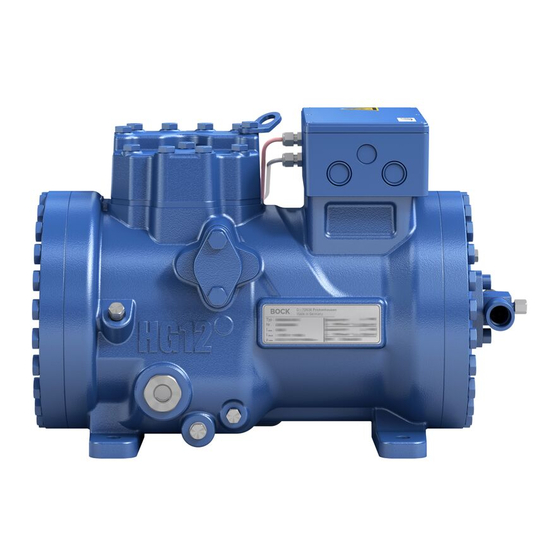
2 | Product description 2.1 Short description • Semi-hermetic two-cylinder reciprocating compressor with suction gas cooled driving motor. • The flow of refrigerant sucked in from the evaporator is led over the engine and provides for a particularly intensive cooling. Thus the engine can be kept on a relatively low temperature level specially during high load. -
Page 7: Type Key
2 | Product description 2.2 Name plate (example) BOCK Bock GmbH, Benzstr. 7 72636 Frickenhausen, Germany HGX12e/40-4 S CO BC12345A001 27,3 10,7/6,2A 111A 32,8 100/100 bar IP66 C 85E SE 55 Öl: BOCKlub E85 Fig. 3 Voltage, circuit, frequency Type designation... -
Page 8: Areas Of Application
3 | Areas of application 3.1 Refrigerants • R744: CO (required CO quality 4.5 (< 5 ppm H 3.2 Oil charge The compressors are filled at the factory with the following oil type: Compressor version ML and S: BOCKlub E85 ATTENTION Property damage possible. -
Page 9: Limits Of Application
3 | Areas of application 3.3 Limits of application ATTENTION Compressor operation is possible within the operating limits. These can be found in Bock compressor selection tool (VAP) under vap.bock.de. Observe the information given there. - Permissible ambient temperature (-20 °C) - (+60 °C). -
Page 10: Compressor Assembly
4 | Compressor assembly INFO New compressors are factory-filled with inert gas. Leave this service charge in the compressor for as long as possible and prevent the ingress of air. Immediately after refrigeration technological connection of the compressor close the shut-off devices in suction-, dis- charge-, oil return line etc. -
Page 11: Pipe Connections
4 | Compressor assembly 4.3 Pipe connections ATTENTION Damage possible. Superheating can damage the valve. Remove the pipe supports therefore from the valve for soldering and accordingly cool the valve body during and after soldering. Only solder using inert gas to inhibit oxidation products (scale). Material soldering / welding connection: S235JR The pipe connections have graduated inside diameters so that pipes with standard dimensions can be used. -
Page 12: Laying Suction And Pressure Lines
4 | Compressor assembly 4.6 Laying suction and pressure lines ATTENTION Property damage possible. Improperly installed pipes can cause cracks and tears which can result in a loss of refrigerant. INFO Proper layout of the suction and pressure lines directly after the compressor is integral to the smooth running and vibration behaviour of the system. -
Page 13: Operating Mode Of The Lockable Service Connections
To ensure the oil return function will work reliably no matter what kind of system configuration you are using, Bock recommends incorporating oil separators or oil level monitoring equipment. The "O" connection is already available from the factory for the purpose of installing the additional oil level monitoring component. -
Page 14: Electrical Connection
5 | Electrical connection Electrical connection DANGER Risk of electric shock! High voltage! Only carry out work when the electrical system is disconnected from the power supply! ATTENTION When attaching accessories with an electrical cable, a minimum bending radius of 3 x the cable diameter must be maintained for laying the cable. -
Page 15: Connection Of The Driving Motor
5 | Electrical connection 5.2 Connection of the driving motor The compressor is designed with a motor for star-delta circuits. ∆ / Y Designation on the name plate Star-delta start-up is only possible on 230 V voltage supply. Example: connection 230 V ∆... - Page 16 5.3 Circuit diagramm for direct start 230 V ∆ / 400 V Y FC1.1 I> I> I> FC1.1 L3 N PE -EC1 Θ B1 B2 INT69G Compressor terminal box Anschlußkasten Verdichter Fig. 14 Cold conductor (PTC sensor) motor winding Thermal protection thermostat (PTC sensor) Load circuit safety switches Control power circuit fuse High pressure safety monitor...
- Page 17 L1.1 L2.1 L3.1 L1.2 P> Θ Θ Main switch Control voltage switch Compressor motor Compressor contactor INT69 G Electronic trigger unit INT69 G Oil sump heater...
-
Page 18: Electronic Trigger Unit Int69 G
5| Electrical connection 5.4 Electronic trigger unit INT69 G The compressor motor is fitted with cold conductor temperature sensors (PTC) connected to the electronic trigger unit INT69 G in the terminal box. In case of excess temperature in the motor winding, the INT69 G deactivates the motor contactor. -
Page 19: Oil Sump Heater
5| Electrical connection Relay position INT69 G Gauge state Relay position Deactivated state 11-12 INT69 G switch-on 11-14 B2 12 14 11 Remove PTC connector 11-12 Fig. 16 Insert PTC connector 11-12 Reset after mains on 11-14 5.7 Oil sump heater In order to avoid damage to the compressor, the compressor has to be equipped with an oil sump heater. -
Page 20: Preparations For Start-Up
6 | Commissioning 6.1 Preparations for start-up INFO In order to protect the compressor against inadmissible operating conditions, high-pressure and low-pressure pressostats controls are mandatory on the installation side. The compressor has undergone trials in the factory and all functions have been tested. There are therefore no special running-in instructions. -
Page 21: Evacuation
6 | Commissioning 6.4 Evacuation ATTENTION Do not start the compressor if it is under vacuum. Do not apply any voltage - even for test purposes (must only be operated with refrigerant). Under vacuum, the spark-over and creepage current distances of the terminal board connection bolts shorten;... -
Page 22: Start-Up
6 | Commissioning 6.6 Start-up WARNING Ensure that both shut-off valves are open before starting the compressor! Check that the safety and protection devices (pressure switch, motor protection, electrical contact protection measures, etc.) are functioning properly. Switch on the compressor and let it run for at least 10 minutes. The machine should reach a state of equilibrium. -
Page 23: Decompression Valves
6 | Commissioning 6.8 Decompression valves ATTENTION The compressor is fitted with two decompression valves. One valve each on the suction and discharge side. If excessive pressures are reached, the valves open and prevent further pressure increase. Thereby CO is blown off to the ambient! In the event that a pressure relief valve activates repeatedly, check valve and replace if necessary as during blow-off extreme con- ditions can occur, which may result in a permanent leak. -
Page 24: Avoiding Slugging
6 | Commissioning 6.9 Avoiding slugging ATTENTION Slugging can result in damage to the compressor and cause refrigerant to leak. To prevent slugging: The complete refrigeration plant must be properly designed. All components must be compatibly rated with each other with regard to output (particularly the evaporator and expansion valves). -
Page 25: Work To Be Carried Out
7.3 Spare part recommendation Available spare parts and accessories can be found on our compressor selection tool under vap.bock.de as well as at bockshop.bock.de. Only use genuine Bock spare parts! 7.4 Lubricants... -
Page 26: Technical Data
8 | Technical data Oil charge (sight glass centre) Oil charge (ex works) Suction line Discharge line Weight permissible fre- 30 - 70 quency range Starting current (rotor locked) Max. power consumption Max. operating current 220-240 V ∆ / 380-420 V Y - 3 - 50 Hz Voltage 265-290 V ∆... - Page 27 8 | Technical data...
-
Page 28: Dimensions And Connections
9 | Dimensions and connections + 0,08 + 0,08 Anschlüsse / 11,54 11,54 Connections Saugabsperrventil, Rohr (L/S Centre of gravity Suction line valve, tube (L/S 99 3,9 99 3,9 Druckabsperrventil, Rohr Discharge line valve, tube Anschluss Saugseite, nicht abs Connection suction side, not lo Anschluss Saugseite, absperrb Connection suction side, lockab + 0,08... - Page 29 9 | Dimensions and connections Suction line see technical data, chapter 8 Discharge line 1 / 8 “ NPTF Connection suction side, not lockable 7 / 16 “ UNF Connection suction side, lockable 1 / 8 “ NPTF Connection discharge side, not lockable 7 / 16 “...
-
Page 30: Declaration Of Incorporation
BOCK ® Declaration of incorporation for incomplete machinery in accordance with EC Machinery Directive 2006/42/EC, Annex II 1. B Manufacturer: Bock GmbH Benzstraße 7 72636 Frickenhausen, Germany We, as manufacturer, declare in sole responsibility that the incomplete machinery Name: Semi-hermetic compressor Types: HG(X)12P/60-4 S (HC) ...... -
Page 31: Service
Dear customer, If you have any questions about installation, operation and accessories, please contact our technical service or specialist wholesaler and/or our representative. The Bock service team can be contacted by phone +49 (0)7022 9454-0 or via service@bock.de. Yours faithfully Bock GmbH... - Page 32 BOCK ® Bock GmbH Benzstraße 7 72636 Frickenhausen Germany Phone +49 7022 9454-0 +49 7022 9454-137 www.bock.de © Bock GmbH. All rights reserved. Subject to modifications.
Need help?
Do you have a question about the HGX12e CO2 LT Series and is the answer not in the manual?
Questions and answers