Table of Contents
Advertisement
Quick Links
Advertisement
Table of Contents

Subscribe to Our Youtube Channel
Related Manuals for BOCK HGX22e S CO2 Series


Summary of Contents for BOCK HGX22e S CO2 Series
- Page 1 /HGX 34 e S CO BOCK HGX e S CO Assembly instructions 96422-01.2021-Gb Translation of the original instructions HGX22e/85-4 S CO HGX22e/105-4 S CO HGX22e/130-4 S CO HGX34e/145-4 S CO HGX34e/170-4 S CO HGX34e/210-4 S CO HGX34e/255-4 S CO BOCK ®...
- Page 2 Observe the safety instructions contained in these instructions. These instructions must be passed onto the end customer along with the unit in which the compres- sor is installed. Manufacturer Bock GmbH 72636 Frickenhausen Contact Bock GmbH Benzstraße 7...
-
Page 3: Table Of Contents
Contents Page Safety 1.1 Identification of safety instructions 1.2 Qualifications required of personnel 1.3 General safety instructions 1.4 Intended use Product description 2.1 Short description 2.2 Name plate 2.3 Type key Areas of application 3.1 Refrigerants 3.2 Oil charge 3.3 Limits of application Compressor assembly 4.1 Storage and transport 4.2 Setting up... -
Page 4: Safety
1 | Safety 1.1 Identification of safety instructions: DANGER Indicates a dangerous situation which, if not avoided, will cause immediate fatal or serious injury WARNING Indicates a dangerous situation which, if not avoided, may cause fatal or serious injury CAUTION Indicates a dangerous situation which, if not avoided, may immediately cause fairly severe or minor injury. ATTENTION Indicates a situation which, if not avoided, may cause property damage INFO Important information or tips on simplifying work 1.2 Qualifications required of personnel WARNING Inadequately qualified personnel poses the risk of accidents, the consequence being serious or fatal injury. Work on compressors must therefore only be performed by personnel with the qualifications listed below: •... -
Page 5: Intended Use
These assembly instructions describe the standard version of the compressor named in the title manufactured by Bock. Bock refrigerating compressors are intended for installation in a machine (within the EU according to the EU Directives 2006/42/EC Machinery Directive, 2014/68/EU Pressure Equipment Directive). -
Page 6: Product Description
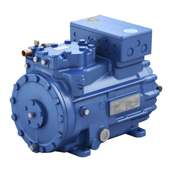
2 | Product description 2.1 Short description • HGX22e S CO : Semi-hermetic two-cylinder reciprocating compressor with suction gas cooled drive motor. • HGX34e S CO : Semi-hermetic four-cylinder reciprocating compressor with suction gas cooled drive motor. • The flow of refrigerant sucked in from the evaporator is led over the engine and provides for a particularly intensive cooling. -
Page 7: Type Key
2 | Product description 2.2 Name plate (example) BOCK Bock GmbH, Benzstr. 7 72636 Frickenhausen, Germany HGX34e/255-4 S CO2 AX34567A045 22,3 44,8/25,9A Δ: 178A Y: 103A 26,8 40/55 IP66 C85E Fig. 3 Voltage, circuit, frequency Type designation 50 Hz Nominal rotation speed Machine number... -
Page 8: Areas Of Application
3.1 Refrigerants • CO : R744 (Recommendation CO2 quality 4.5 (< 5 ppm H 3.2 Oil charge The compressors are filled at the factory with the following oil type: Bock C 85 E (only this oils may be used) ATTENTION Property damage possible. The oil level must be in the max. HGX22e S CO visible part of the sight 0,5 Ltr. -
Page 9: Compressor Assembly
4| Compressor assembly INFO New compressors are factory-filled with inert gas. Leave this service charge in the compressor for as long as possible and pre- vent the ingress of air. Check the compressor for transport damage before starting any work. 4.1 Storage and transportation Storage at (-30°C) - (+70°C), maximum permissible relative humidity 10% -95 %, no condensation. -
Page 10: Pipes
4| Compressor assembly The pipe connections have graduated inside diameters so that pipes with standart millimetre and inch dimensions can be used. The connection diameters of the shut-off valves are rated for maximum compressor output. The actual required pipe cross section must be matched to the output. The same applies for non-return valves. Fig. -
Page 11: Operating The Shut-Off Valves
4| Compressor assembly 4.6 Operating the shut-off valves Before opening or closing the shut-off valve, release the valve spindle seal by approx. ¼ of a turn counter-clockwise. After activating the shut-off valve, re-tighten the adjustable valve spindle seal clockwise. Tighten Release Valve spindle seal Fig. -
Page 12: Electrical Connection 12 Dgb
4| Compressor assembly 4.8 Suction pipe filter For systems with long pipes and higher degree of contamination, a filter on the suction-side is recommended. The filter has to be be renewed depending on the degree of contamination (reduced pressure loss). 5| Electrical connection Electrical connection DANGER Risk of electric shock! High voltage! -
Page 13: Connection Of The Driving Motor
5| Electrical connection 5.2 Connection of the driving motor The compressor is designed with a motor for star-delta circuits. Designation on the name plate ∆ / Y Star-delta start-up is only possible on 230 V voltage supply. Example: 230 V ∆ 400 V Y L1 L2 Direct start Star-delta start Direct start only L1 L2 L1 L2 L1 L2 L1 L2 INFO... - Page 14 5.3 Circuit diagramm for direct start 230 V ∆ / 400 V Y FC1.1 I> I> I> FC1.1 L3 N PE -EC1 Θ B1 B2 INT69G Compressor terminal box Anschlußkasten Verdichter Fig. 12 High pressure safety controller Safety chain (high/low pressure monitoring) Thermal protection thermostat (PTC sensor) Release switch (thermostat/pressostat) Oil sump heater Compressor motor...
- Page 15 L1.1 L2.1 L3.1 L1.2 P> Θ Θ FC1.1 Motor protection switch Control power circuit fuse INT69 G Electronic trigger unit INT69 G Main switch Mains contactor Control voltage switch...
-
Page 16: Electronic Trigger Unit Int69 G
5| Electrical connection 5.4 Electronic trigger unit INT69 G The compressor motor is fitted with cold conductor temperature sensors (PTC) connected to the electronic trigger unit INT69 G in the terminal box. In case of excess temperature in the motor winding, the INT69 G deactivates the motor contactor. -
Page 17: Oil Sump Heater (Accessories)
5| Electrical connection 5.6 Function test of the trigger unit INT69 G Before commissioning, after troubleshooting or making changes to the control power circuit, check the functionality of the trigger unit. Perform this check using a continuity tester or gauge. Relay position INT69 G Gauge state Relay position... -
Page 18: Commissioning
6| Commissioning 6.1 Preparations for start-up INFO To protect the compressor against inadmissible operating conditions, high pressure and low pressure pressostats are mandatory on the installation side. The compressor has undergone trials in the factory and all functions have been tested. There are therefore no special running-in instructions. Check the compressor for transport damage! WARNING When the compressor is not running, depending on ambient... -
Page 19: Evacuation
6| Commissioning 6.4 Evacuation ATTENTION Do not start the compressor if it is under vacuum. Do not apply any voltage - even for test purposes (must only be operated with refrigerant). Under vacuum, the spark-over and creepage current distances of the terminal board connection bolts shorten;... -
Page 20: Start-Up
6| Commissioning 6.6 Start-up WARNING Ensure that both shut-off valves are open before starting the compressor! Check that the safety and protection devices (pressure switch, motor protection, electrical contact protection measures, etc.) are functioning properly. Switch on the compressor and let it run for at least 10 minutes. The machine should reach a state of equilibrium. -
Page 21: Filter Dryer
6| Commissioning 6.8 Avoid slugging ATTENTION Slugging can result in damage to the compressor and cause refrigerant to leak. To prevent slugging: The complete refrigeration system must be properly designed. All components must be compatibly rated with each other with regard to output (particularly the evaporator and expansion valves). Suction gas superheat at the compressor input should be 15 K. -
Page 22: Maintenance
Annual checks: Oil level, leak tightness, running noises, pressures, temperatures, function of auxiliary devices such as oil sump heater, pressure switch. 7.3 Spare part recommendation/accessories Available spare parts and accessories can be found on our compressor selection tool under vap.bock.de as well as at bockshop.bock.de. Only use genuine Bock spare parts! -
Page 23: Decommissioning
7| Maintenance 7.4 Extract from the lubricants table For operation with CO the Bock oil C 85 E is necessary! 7.5 Decommissioning Close the shut-off valves on the compressor. CO does not need to be recycled and can therefore be blown off into the environment. It is essential to ensure good ventilation or conduct the CO into the outdoors to avoid danger of suffocation. -
Page 24: Technical Data
8| Technical data Oil charge Weight 220-240 V ∆ / 380-420 V Y - 3 - 50 Hz 265-290 V ∆ / 440-480 V Y - 3 - 60 Hz No. of cylinders... - Page 25 8| Technical data Oil charge Weight 220-240 V ∆ / 380-420 V Y - 3 - 50 Hz 265-290 V ∆ / 440-480 V Y - 3 - 60 Hz No. of cylinders...
-
Page 26: Dimensions And Connections
Geprüft / Appr. of the grant of a patent, utility model or design. Geprüft / Verified Zuder 18.05.16 GEA Bock GmbH - Benzstraße 7 - 72636 Frickenhausen - Germany - www.bock.de Freigabe / Approved Layh Layh Maß Dimension Passung / Clearance 18.05.16... - Page 27 Offenders will be held liable for the Sight glass payment of damages. All rights reserved in the event GEA Bock GmbH - Benzstraße 7 Zust. / Rev. Maß Dimension Passung / Clearance Änd.-Nr.
-
Page 28: Declaration Of Installation
10| Declaration of installation Declaration of incorporation for incomplete machinery in accordance with EC Machinery Directive 2006/42/EC, Annex II 1. B Manufacturer: Bock GmbH Benzstraße 7 72636 Frickenhausen, Germany We, as manufacturer, declare in sole responsibility that the incomplete machinery... -
Page 29: Service
Dear customer, if you have any questions about installation, operation and accessories, please contact our technical service or specialist wholesaler and/or our representative. The Bock service team can be contacted by phone, +49 (0)7022 9454-0 or via service@bock.de Yours faithfully Bock GmbH... - Page 30 BOCK ® Bock GmbH Benzstraße 7 72636 Frickenhausen Germany Phone +49 7022 9454-0 +49 7022 9454-137 www.bock.de © Bock GmbH. All rights reserved. Subject to modifications. Printed in Germany.
Need help?
Do you have a question about the HGX22e S CO2 Series and is the answer not in the manual?
Questions and answers