Table of Contents
Advertisement
Quick Links
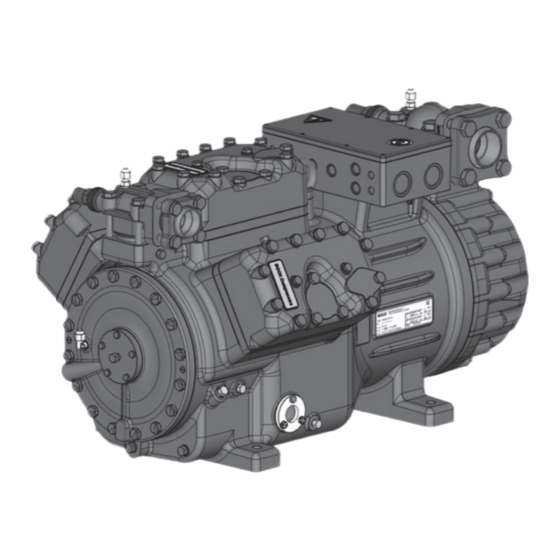
BOCK HG66e (HC/LG)
Assembly instructions
96446-11.2022-Gb
Translation of the original instructions
HG(X)66e/1340-4 (S)
HG(X)66e/1540-4 (S)
HG(X)66e/1750-4 (S)
HG(X)66e/2070-4 (S)
HGX66e/1340 ML 31 LG
HGX66e/1540 ML 36 LG
HGX66e/1750 ML 44 LG
HGX66e/2070 ML 50 LG
BOCK
®
HG66e/1340-4 (S) HC
HG66e/1540-4 (S) HC
HG66e/1750-4 (S) HC
HG66e/2070-4 (S) HC
HGX66e/1340 S 37 LG
HGX66e/1540 S 42 LG
HGX66e/1750 S 50 LG
HGX66e/2070 S 60 LG
colour the world
of tomorrow
Advertisement
Table of Contents


Need help?
Do you have a question about the HG66e/1340-4 and is the answer not in the manual?
Questions and answers