
Related Manuals for BOCK Pluscom HG34P Series


Summary of Contents for BOCK Pluscom HG34P Series
- Page 1 HG34P - CO /R410A up to 40 bar Operating instructions Types: HGX34P/215-4 CO HGX34P/255-4 CO HGX34P/215-4 R410A HGX34P/215-4 S R410A HGX34P/255-4 S R410A HGX34P/315-4 R410A...
- Page 2 The Bock service team is available by phone under +49 7022 9454-0, by e-mail under mail@bock.de or on the internet under www.bock.de. In addition, for...
-
Page 3: Table Of Contents
Contents page Safety instructions Product description Use as intended Short description Main and functional parts Name plate Type key Areas of application CO Refrigerant, oil filling, operating limits Areas of application R410A Refrigerant, oil filling, operating limits Installation Setting up Pipe connections Pipes Shutoff valves... -
Page 4: Safety Instructions
Safety instructions The Bock refrigerating compressors named in the title are intended for installation Die im Titel genannten Bock-Kältemittelverdichter sind für den Einbau in Maschinen in machines (within the EU according to EU directive 98/37/EC Machinery Directive, (innerhalb der EU gemäß den EU-Richtlinien 98/37/EG -Maschinenrichtlinie-, 97/23/ 97/23/EC Pressure Equipment Directive and 73/23/EC Low Voltage Directive). -
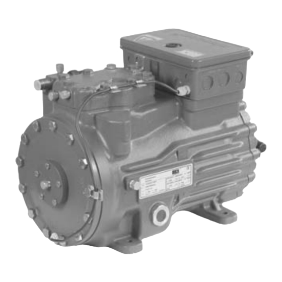
Page 5: Product Description
This operating manual describes the compressor named in the title in the standard sion manufactured by Bock. version. Bock refrigerant compressors are intended for use in refrigeration plants using the refrigerants stated below and under compliance with the operating limits. Any other... -
Page 6: Name Plate
Product description Nameplate (example) Nameplate (example) 6 Voltage, switching, frequency 6 Voltage, switching, frequency 1 Type designation 1 Type designation 50 Hz 50 Hz 7 Rated speed 7 Rated speed 2 Machine number 2 Machine number 8 Swept volume 8 Swept volume 3 Maximum operating current 3 Maximum operating current 9 Voltage, switching, frequency... -
Page 7: Areas Of Application
The compressors are filled with the following oil grade in the factory: We recommend using the above oil grades for refi lling. Alternatives: see excerpt from Bock C 55 E (only this oil may be used) the Bock lubricant table page 18. -
Page 8: Areas Of Application R410A
We recommend using the above oil grades for refi lling. Alternatives: see excerpt from Fuchs Rensio SE 55 (To alternatives see lubricants, P. 22) the Bock lubricant table page 18. Limits of application diagrams ● It is possible to operate the compressor within the operating limits shown Operation of the compressor is possible within the limits shown in the diagrams. -
Page 9: Installation
Installation Compressors are fi lled with protective gas ex works (approx. 3 bar nitrogen! ● Leave protective gas fi lling in the compressor up to evacuation. ● Do not open shutoff valves up to evacuation. ● Absolutely avoid entry of air! Pipe connections The pressure and suction shutoff valves have graduated Erection... -
Page 10: Pipes
Compressors are fi lled with protective gas ex works (approx. 3 bar nitrogen! ● Leave protective gas fi lling in the compressor up to evacuation. Installation ● Do not open shutoff valves up to evacuation. ● Absolutely avoid entry of air! Pipe connections The pressure and suction shutoff valves have graduated inside diameters, so that pipes in the customary millimeter... -
Page 11: Shutoff Valves
Installation Shut- off valves Comply with the safety instructions on page 9! Before opening or closing the shut-off valve, turn the valve spindle seal approx. ¼ of a turn counter-clockwise. After activating the shut-off valve, tighten the valve spindle seal again clockwise. -
Page 12: Electrical System
Electrical system Electrical connection Electrical connections High voltage! Perform work only with the electrical installation disconnected from the power supply! Make connection of the compressor motor according to the circuit diagram (see inside of terminal box). Comply with local safety regulations for electrical work and the safety standards EN 60204, EN 60335 when connecting. -
Page 13: Connection Of The Drive Motor
Electrical system Connection of the drive motor The compressor is equipped with a motor in ∆ / Y design Designation on the name plate Designation on the terminal box ∆ / Y ∆ / Y - starting is only possible in ∆ - voltage-range. Example: 230 V ∆... - Page 14 Electrical system Circuit diagram direct start 230 V ∆ / 400 V Y 1-2 Connections for PTC sensor (MP10) 1-2 Connections for PTC sensor R1 PTC sensor motor winding R1 PTC sensor motor winding R2 Heat protection thermostat (PTC sensor) R2 Heat protection thermostat (PTC sensor) F1 Motor safety switches F1 Motor safety switches...
- Page 15 ...
- Page 16 Electrical system Electronic trigger MP 10 The compressor motor is equipped with posistor temperature sensors (PTC) which are wired to the electronic trigger MP 10 in the terminal box. The stand-by mode is indicated by the light diode H3 (green) when mains voltage is applied. In the event of overtempe- rature in the motor winding, the device switches the compressor off and signal lamp H1 lights up red.
-
Page 17: Oil Sump Heater
Electrical system Function test of the electronic trigger MP 10 Before starting up and after any faults or changes to the control power circuit of the machine, check the electronic trigger to ensure that it functions properly: LED H1 LED H2 LED H3 Pos Procedure green ●... -
Page 18: Start-Up
Start- up Inbetriebnahme Preparations for Initial commissioning Vorbereitungen zur Inbetriebnahme Vorbereitungen zur Inbetriebnahme The compressor has undergone trials in the factory and all functions have been tested. Der Verdichter ist im Werk probegelaufen und auf sämtliche Funktionen geprüft worden. There are therefore no special running-in instructions. Besondere Einlaufvorschriften müssen daher nicht beachtet werden. -
Page 19: Refrigerant Filling
Start- up Evakuieren Evakuieren ● Zuerst Anlage evakuieren, dann Verdichter in den Evakuiervorgang einbeziehen: • Verdichter druckentlasten Filling with coolant • Saug- und Druckabsperrventil öffnen. Wear personal safety gear! • Mit der Vakuumpumpe auf Saug- und Hochdruckseite evakuieren. • Vakuum < 1,5 mbar bei abgesperrter Pumpe. Check that the compressor suction and discharge shut-off valves are open. -
Page 20: Connection Of The Oil Level Regulator
Start- up Liquid sluggings Liquid slugging can cause damage to the compressor and leakage of refrigerant. To avoid liquid slugging, the following points should be observed: The whole plant must be properly designed. All components must be rated to be compatible with each other with regard to output (particularly evaporator and expansion valve). -
Page 21: Maintenance
80305 80306 set connecting rod 80368 BS gaskets 08534 Nur Original-Bock-Ersatzteile verwenden! Only use original support Bock spare parts! Use only original Bock spare parts! Accessories You can find information on available accessories in our product catalogue and at www.bock.de. -
Page 22: Lubricants
Alternatives to this see following lubricant table. Schmierstoffe FUCHS Reniso SP 46 MOBIL SHC 425 SUNOIL Suniso 4GS R410A Bock standard oil grade Recommended alternatives Bock-Serienölsorte Empfohlene Alternativen SHELL Clavus SD 22-12 TEXACO Capella WF 46 Für HFKWs (z.B. - Page 23 220-240 V Δ / 380-420 V Y - 3 - 50 Hz 265-290 V Δ / 440-480 V Y - 3 - 60 Hz...
-
Page 24: Dimensions And Connections
Maß ca.285 DV B1 Dimensions and connections Maß ca.285 DV B1 H,D1 ca.285 DV B1 H,D1 46 (43) 4x 12 79 (74) ca.515 (510) 46 (43) 4x 12 Schwingungsdämpfer Vibration absorbers 79 (74) Amortisseurs de vibration ca.515 (510) 46 (43) 4x 12 Maße in ( ) nur für HGX34P/215+25 Dimensions in ( ) only for HGX34P/2... -
Page 25: Conformity And Manufacturer's Declaration
Conformity and manufacturer´s declaration DECLARATION OF CONFORMITY CE 96 for use of the compressors within the European Union (as per EU low voltage directive 73/23/EEC, in the version 93/68/EEC) We herewith declare that the hermetic refrigerating compressors named in the title comply with the low voltage directive 73/23/EEC in the version 93/68/EEC. - Page 28 Sehr geehrter Kunde, Bock-Verdichter sind hochwertige, zuver Vorteile in vollem Umfange und über den können, beachten Sie unbedingt die folg Montage, Betrieb und Zubehör wenden S Kältefachgroßhandel bzw. unsere Vertret +49 7022 9454-0, via e-mail: mail@boc chigen Raum steht darüber hinaus die ko bis samstags zwischen 8 und 21 Uhr zur www.bock.de...
Need help?
Do you have a question about the Pluscom HG34P Series and is the answer not in the manual?
Questions and answers