Table of Contents

Related Manuals for BOCK HGX44e CO2


Summary of Contents for BOCK HGX44e CO2
- Page 1 BOCK HGX 44 e CO (subcritical) Assembly instructions 96507-06.2021-Gb Translation of the original instructions HGX44e/320-4 S CO HGX44e/390-4 S CO HGX44e/475-4 S CO HGX44e/565-4 S CO BOCK ® colour the world of tomorrow...
-
Page 2: Table Of Contents
Observe the safety instructions contained in these instructions. These instructions must be passed onto the end customer along with the unit in which the compres- sor is installed. Manufacturer Bock GmbH 72636 Frickenhausen Contact Bock GmbH Benzstraße 7... - Page 3 Contents Page Areas of application 3.1 Refrigerants 3.2 Oil charge 3.3 Limits of application Compressor assembly 4.1 Storage and transport 4.2 Setting up 4.3 Pipe connections 4.4 Pipes 4.5 Laying suction and pressure lines 4.6 Operating the shut-off valves 4.7 Operating mode of the lockable service connections 4.8 Suction pipe filter Electrical connection 5.1 Information for contactor and motor contactor selection...
-
Page 4: Safety
1| Safety 1.1 Identification of safety instructions: DANGER Indicates a dangerous situation which, if not avoided, will cause immediate fatal or serious injury WARNING Indicates a dangerous situation which, if not avoided, may cause fatal or serious injury CAUTION Indicates a dangerous situation which, if not avoided, may immediately cause fairly severe or minor injury. -
Page 5: Intended Use
These assembly instructions describe the standard version of the compressor named in the title manufactured by Bock. Bock refrigerating compressors are intended for installation in a machine (within the EU according to the EU Directives 2006/42/EC Machinery Directive, 2014/68/EU Pressure Equipment Directive). -
Page 6: Product Description
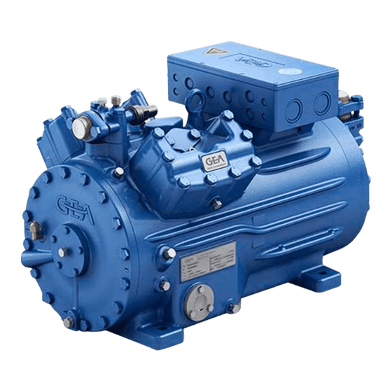
2| Product description 2.1 Short description • Semi-hermetic four-cylinder reciprocating compressor with suction-gas cooled drive motor. • The flow of refrigerant sucked in from the evaporator is led over the engine and provides for a particularly intensive cooling. Thus the engine can be kept special during high load on a relatively low temperature level. -
Page 7: Type Key
2| Product description 2.2 Name plate (example) BOCK Bock GmbH, Benzstr. 7 72636 Frickenhausen, Germany HGX44e/565-4 S CO2 BC12345A001 67,0 35,0 A 80,4 101 A 174 A BOCK lub E85 30/55 C85E Fig. 3 Type designation Voltage, circuit, frequency 50 Hz... -
Page 8: Areas Of Application
3.3 Limits of application ATTENTION Compressor operation is possible within the operating limits. These can be found in Bock compressor selection tool (VAP) under vap.bock.de. Observe the information given there. - Permissible ambient temperature (-20°C) - (+60°C). -
Page 9: Compressor Assembly
4| Compressor assembly INFO New compressors are factory-filled with inert gas. Leave this service charge in the compressor for as long as possible and pre- vent the ingress of air. Check the compressor for transport damage before starting any work. 4.1 Storage and transportation Storage at (-30°C) - (+70°C), maximum permissible relative humidity 10% -95 %, no condensation. -
Page 10: Pipe Connections
4| Compressor assembly 4.3 Pipe connections ATTENTION Damage possible Superheating can damage the valve. Remove the pipe supports therefore from the valve for soldering/ welding. Only soldering/welding using inert gas to inhibit oxida- tion products (scale). The pipe connections have graduated inside diameters so that pipes with standart millimetre and inch dimensions can be used. -
Page 11: Operating The Shut-Off Valves
4| Compressor assembly A rule of thumb: Always lay the first pipe section starting from the shut-off valve downwards and parallel to the drive shaft. Rigid As short as fixed point possible Fig. 6 4.6 Operating the shut-off valves Before opening or closing the shut-off valve, release the valve spindle seal by approx. ¼ of a turn counter-clockwise. -
Page 12: Operating Mode Of The Lockable Service Connections
4| Compressor assembly 4.7 Operating mode of the lockable service connections Connection cannot be Service connec- shut off tion closed Pipe connection Connection Spindle blocked Fig. 9 Opening the shut-off valve: Compressor Spindle: turn to the left (counter-clockwise) as far as it will go. —>... -
Page 13: Electrical Connection
5| Electrical connection Electrical connection DANGER Risk of electric shock! High voltage! Only carry out work when the electrical system is disconnected from the power supply! ATTENTION When attaching accessories with an electrical cable, a minimum bending radius of 3 x the cable diameter must be maintained for laying the cable. -
Page 14: Basic Circuit Diagram For Partial Winding Start With Standard Motor
5.3 Basic circuit diagram for partial winding start with standard motor FC1.2 FC1.1 I> I> I> I> I> I> FC1.1 FC1.2 L3 N PE Y/YY B1 B2 INT69 Anschlußkasten Verdichter Compressor terminal box Fig. 11 High pressure safety controller Safety chain (high/low pressure monitoring) Cold conductor PTC sensor motor winding Thermal protection thermostat (PTC sensor) Oil temperature sensor... - Page 15 FC1.1/1.2 Motor protection switch Control power circuit fuse INT69 G Electronic trigger unit INT69 G Timer relay for contactor switch Main switch PW INT69 HG44/66 Mains contactor (part winding 1) Mains contactor (part winding 2) BOCK COMPRESSORS Control voltage switch...
- Page 16 5| Electrical connection The motor is wired for direct start (YY) at the factory. For part winding start (Y/YY) the bridges must be removed and the motor feed line connected according to the circuit diagram: 400 V Direktstart YY Teilwicklungsstart Y/YY Direct start YY Part winding start Y/YY ATTENTION Failure to do this results in opposed rotary fields and results in...
-
Page 17: Electronic Trigger Unit Int69 G
5| Electrical connection 5.4 Electronic trigger unit INT69 G The compressor motor is fitted with cold conductor temperature sensors (PTC) connected to the electronic trigger unit INT69 G in the terminal box. In case of excess temperature in the motor winding, the INT 69 G deactivates the motor contactor. - Page 18 5| Electrical connection 5.6 Function test of the trigger unit INT69 G Before commissioning, after troubleshooting or making changes to the control power circuit, check the functionality of the trigger unit. Perform this check using a continuity tester or gauge. Gauge state Relay position Relay position INT69 G...
-
Page 19: Oil Sump Heater (Accessories) D
5| Electrical connection 5.7 Oil sump heater (accessories) In order to avoid damage to the compressor, the compressor must be equipped with an oil sump heater. ATTENTION The oil sump heater must generally be connected and operated. When the compressor is at a standstill, refrigerant diffuses into the lubricating oil of the compressors housing, depending on pressure and ambient temperature. -
Page 20: Preparations For Start-Up
6| Commissioning 6.1 Preparations for start-up INFO To protect the compressor against inadmissible operating conditions, high pressure and low pressure pressostats are mandatory on the installation side. The compressor has undergone trials in the factory and all functions have been tested. There are therefore no special running-in instructions. -
Page 21: Evacuation
6| Commissioning 6.4 Evacuation ATTENTION Do not start the compressor if it is under vacuum. Do not apply any voltage - even for test purposes (must only be operated with refrigerant). Under vacuum, the spark-over and creepage current distances of the terminal board connection bolts shorten;... -
Page 22: Start-Up
6| Commissioning 6.6 Start-up WARNING Ensure that both shut-off valves are open before starting the compressor! Check that the safety and protection devices (pressure switch, motor protection, electrical contact protection measures, etc.) are functioning properly. Switch on the compressor and let it run for at least 10 minutes. The machine should reach a state of equilibrium. -
Page 23: Avoiding Slugging
6| Commissioning 6.8 Avoiding slugging ATTENTION Slugging can damage the compressor and cause refrigerant to leak. To prevent slugging: The complete refrigeration system must be properly designed. All components must be compatibly rated with each other with regard to output (particularly the evaporator and expansion valves). Suction gas superheat at the compressor input should be 15 K. -
Page 24: Maintenance
Only use genuine Bock spare parts! 7.4 Lubricants the oil BOCK lub E85 is necessary! For operation with CO 7.5 Decommissioning It is essential to ensure good ventilation to avoid danger of suffocation by releasing CO . -
Page 25: Technical Data
8 | Technical data Oil charge Weight 380-420 V Y/YY - 3 - 50 Hz PW 440-480 V Y/YY - 3 - 60 Hz PW PW = Part Winding Winding ratio : 50 % / 50 % No. of cylinders... -
Page 26: Dimensions And Connections
9 | Dimensions and connections Centre of gravity H,D1 A1 SV H,D1 HGX44e/ Anschlüsse / HGX44e/ 390-4 S CO2 HGX44e/ Connections 320-4 S CO2 475-4 S CO2 Anschlüsse / HGX44e/ 390-4 S CO2 565-4 S CO2 Connections 320-4 S CO2 475-4 S CO2 Saugabsperrventil, Rohr (L/SW)*... - Page 27 9 | Dimensions and connections Suction line see technicla data, Chapte 8 Discharge line Connection suction side, not lockable 8 “ NPTF Connection suction side, lockable 16 “ UNF Connection discharge side, not lockable 8 “ NPTF Connection discharge side, lockable 16 “...
-
Page 28: Declaration Of Incorporation
BOCK ® Declaration of incorporation for incomplete machinery in accordance with EC Machinery Directive 2006/42/EC, Annex II 1. B Manufacturer: Bock GmbH Benzstraße 7 72636 Frickenhausen, Germany We, as manufacturer, declare in sole responsibility that the incomplete machinery Name: Semi-hermetic compressor Types: HG(X)12P/60-4 S (HC) .... -
Page 29: Service
Dear customer, if you have any questions about installation, operation and accessories, please contact our technical service or specialist wholesaler and/or our representative. The Bock service team can be contacted by phone, +49 (0)7022 9454-0 or via service@bock.de Yours faithfully Bock GmbH... - Page 30 BOCK ® Bock GmbH Benzstraße 7 72636 Frickenhausen Germany Phone +49 7022 9454-0 +49 7022 9454-137 www.bock.de © Bock GmbH. All rights reserved. Subject to modifications. Printed in Germany.
Need help?
Do you have a question about the HGX44e CO2 and is the answer not in the manual?
Questions and answers