
Related Manuals for Sentiotec IS1 P-IS1-T


Summary of Contents for Sentiotec IS1 P-IS1-T
- Page 1 Infrared control unit P-IS1-T INSTRUCTIONS FOR INSTALLATION AND USE English Version 04/23 Ident-Nr. 1-026-216...
-
Page 2: Table Of Contents
Table of Contents 1. About this instruction manual 2. Important information for your safety 2.1. Intended use 2.2. Safety information for the installer 2.3. Safety information for the user 3. Product description 3.1. Scope of delivery 3.2. Optional accessories 3.3. Product functions 4. -
Page 3: About This Instruction Manual
The current installation and operating instructions can also be found in the downloads section of our website: www.sentiotec.com/downloads. Symbols used for warnings These installation and operating instructions feature warning symbols next to activities presenting a hazard to the user. -
Page 4: Important Information For Your Safety
Instructions for installation and use p. 4/22 2. Important information for your safety The IS1 infrared control unit has been produced in accordance with the safety regulations applicable for technical units. However, hazards may occur during use. You should therefore adhere to the following safety information and the specific warnings in the individual chapters. -
Page 5: Safety Information For The Installer
Instructions for installation and use p. 5/22 2.2. Safety information for the installer ● Installation may only be performed by a qualified electrician or similarly qualified person. ● Installation and connection of the infrared control unit may only be performed when the power supply is disconnected. ●... -
Page 6: Safety Information For The User
Instructions for installation and use p. 6/22 2.3. Safety information for the user ● The device must not be used by children under 8 years old. ● The device may only be used by children over 8 years old, by persons with limited psychological, sensory or mental capabili- ties or by persons with lack of experience/knowledge under the following conditions:... -
Page 7: Product Description
Instructions for installation and use p. 7/22 3. Product description 3.1. Scope of delivery ● IS1 infrared control unit ● 1.6 m mains connection cable ● 1.5 m room sensor with silicone cable ● Installation material ● Instructions for installation and use 3.2. -
Page 8: Installation
Installation instructions, only for experts p. 8/22 4. Installation The infrared control unit can either be surface-mounted or recess mounted. 4.1. Preparing for surface mounting To mount the control unit on a surface, you need to make cable bushings in the cabin wall. -
Page 9: Preparing For Recess Mounting
Installation instructions, only for experts p. 9/22 4.2. Preparing for recess mounting Mounting the control unit in a recess requires a cut-out section. ● Cut-out section size: 160 mm x 102 mm ● Mounting depth: 39.5 mm R=5 mm ► Ensure that the control unit has sufficient rear ventilation! 4.3. -
Page 10: Electrical Connection
Installation instructions, only for experts p. 10/22 5. Electrical connection Before mounting the control unit, the electrical connections must be completed. Observe the following points when connecting the power: ● Installation may only be performed by a qualified electrician or similarly quali- fied person. - Page 11 Installation instructions, only for experts p. 11/22 1. Guide the connection cable for the room sensor through the cable bushing in the middle of the housing cover. Do not, under any circumstances, guide the sensor cables through the existing openings at the bottom. 2.
-
Page 12: Removing The
Installation instructions, only for experts p. 12/22 5.1. Removing the front cover The front cover must be removed to mount the controller on the wall. To do this, use a flat screwdriver. ● Insert the screwdriver into the hole provided at the bottom edge of the control unit. -
Page 13: Final Assembly
Installation instructions, only for experts p. 13/22 6. Final assembly After all the electrical connections have been made, the control unit can be mounted. Work on the housing must only be carried out with a screwdriver. Using a cordless screwdriver may cause irreparable damage to the housing. 6.1. -
Page 14: Final Assembly - Recess Mounting
Installation instructions, only for experts p. 14/22 6.2. Final assembly - recess mounting For recess mounting the control unit is placed in a wall cut-out section and at- tached using the 16 mm Torx screws included. DANGER! When tightening the screws, be careful not to damage any cables in the wall. -
Page 15: Fitting The Sensor
Installation instructions, only for experts p. 15/22 6.3. Fitting the sensor The room sensor is fitted in the infrared cabin about 30 cm below the ceiling or according to the cabin manufacturer's instructions. CAUTION - incorrect readings: If the room sensor is fitted too near the heater, it will produce incorrect measured values. -
Page 16: Adjusting The Heating Time Limit
Installation instructions, only for experts p. 16/22 7. Adjusting the heating time limit The heating time limit for the control unit is set at the factory to 99 minutes. This can be extended up to 24 hours by setting the jumper as described below. The jumper set is available as an accessory under the order number O-JUMP. -
Page 17: Operation
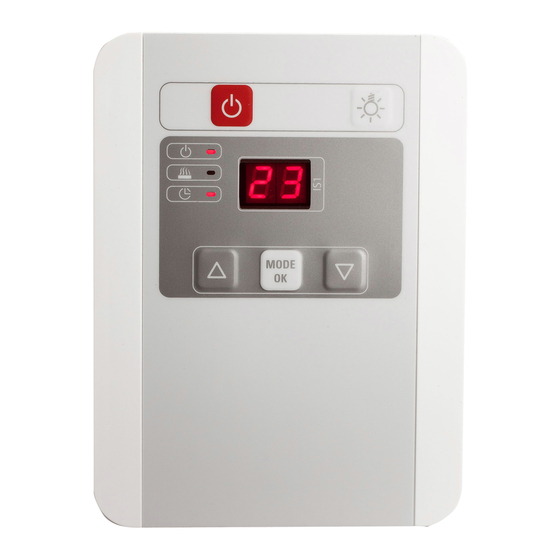
Instructions for use for the user p. 17/22 8. Operation 8.1. Operating and display elements Fig. 1:Operating and display elements Operating elements: Display elements: 1 On/Off button 6 Temperature and operating time display 2 Light 7 Temperature selection 3 + button 8 Operating time selection 4 Mode/OK button 5 - button... -
Page 18: Quick Start
Instructions for use for the user p. 18/22 8.2. Quick start ● Press button 1 to switch on the control unit. ► The current cabin temperature appears in display 6 and display 7 lights up. You can adjust the required temperature with buttons 3 and 5. While you are making the setting, display 6flashes. -
Page 19: Description Of The Functions And Control Elements
Instructions for use for the user p. 19/22 8.3. Description of the functions and control elements Observe Fig. 1:Operating and display elements on page 17. ● On/Off button Use this button to switch the control unit on and off (standby). If the operating time and temperature have already been set, the control units starts immediately with the previously selected settings. - Page 20 Instructions for use for the user p. 20/22 ● Temperature selector Here you can set the required temperature. Press buttons 3 and 5 to make the setting. While the target temperature is being displayed, display 6 flashes. You can now confirm the set value by pressing 4 or wait 5 seconds until the value is set automatically.
-
Page 21: Troubleshooting
Instructions for installation and use p. 21/22 9. Troubleshooting The infrared control unit is equipped with diagnostic software which monitors the system status when switching on and during operation. As soon as the diagnostic software identifies an error, the infrared control unit switches the heating system off. Error Description Cause / rectification... -
Page 22: Disposal
10. Disposal ● Dispose of packaging materials in accordance with the applicable disposal regulations. ● Used devices contain reusable materials, as well as hazardous substances. Do not dispose of your used device with household waste, but do so in accordance with the locally applicable regula- tions. - Page 23 Infrarotsteuerung P-IS1-T MONTAGE- UND GEBRAUCHSANWEISUNG Deutsch Version 04/23 Ident-Nr. 1-026-216...
- Page 24 Inhaltsverzeichnis 1. Zu dieser Anleitung 2. Wichtige Hinweise zu Ihrer Sicherheit 2.1. Bestimmungsgemäßer Gebrauch 2.2. Sicherheitshinweise für den Monteur 2.3. Sicherheitshinweise für den Anwender 3. Produktbeschreibung 3.1. Lieferumfang 3.2. Optionales Zubehör 3.3. Produktfunktionen 4. Montage 4.1. Vorbereiten der Montage - Aufputz 4.2.
-
Page 25: Zu Dieser Anleitung
Sie sie in der Nähe der Infrarotsteuerung auf. So können Sie jederzeit Informa- tionen zu Ihrer Sicherheit und zur Bedienung nachlesen. Sie finden die aktuellen Montage- und Gebrauchsanweisungen im Down- loadbereich unserer Webseite auf www.sentiotec.com/downloads. Symbole in Warnhinweisen In dieser Montage- und Gebrauchsanweisung ist vor Tätigkeiten, von denen eine Gefahr ausgeht, ein Warnhinweis angebracht. -
Page 26: Wichtige Hinweise Zu Ihrer Sicherheit
Montage- und Gebrauchsanweisung S. 4/22 2. Wichtige Hinweise zu Ihrer Sicherheit Die Infrarotsteuerung IS1 ist nach anerkannten sicherheitstech- nischen Regeln gebaut. Dennoch können bei der Verwendung Gefahren entstehen. Befolgen Sie deshalb die folgenden Sicher- heitshinweise und die speziellen Warnhinweise in den einzelnen Kapiteln. -
Page 27: Sicherheitshinweise Für Den Monteur
Montage- und Gebrauchsanweisung S. 5/22 2.2. Sicherheitshinweise für den Monteur ● Die Montage darf nur durch eine Elektrofachkraft oder eine ver- gleichsweise qualifizierte Person ausgeführt werden. ● Montage- und Anschlussarbeiten an der Infrarotsteuerung dürfen nur im spannungsfreien Zustand durchgeführt werden. ●... -
Page 28: Sicherheitshinweise Für Den Anwender
Montage- und Gebrauchsanweisung S. 6/22 2.3. Sicherheitshinweise für den Anwender ● Das Gerät darf nicht von Kindern unter 8 Jahren verwendet werden. ● Das Gerät darf von Kindern über 8 Jahren, von Personen mit verringerten psychischen, sensorischen oder mentalen Fähig- keiten und von Personen mit Mangel an Erfahrung und Wissen unter folgenden Bedingungen verwendet werden: –... -
Page 29: Produktbeschreibung
Montage- und Gebrauchsanweisung S. 7/22 3. Produktbeschreibung 3.1. Lieferumfang ● Infrarotsteuerung IS1 ● Netzanschlussleitung 1,6 m ● Raumfühler mit Silikonleitung 1,5 m ● Montagematerial ● Montage- und Gebrauchsanweisung 3.2. Optionales Zubehör ● IR-IS-A03 Adapterleitung für Strahler und Wärmeplatten (0,3 m) ●... -
Page 30: Montage
Montageanweisung – nur für Fachpersonal S. 8/22 4. Montage Die Infrarotsteuerung kann wahlweise aufputz oder versenkt montiert werden. 4.1. Vorbereiten der Montage - Aufputz Um die Steuerung aufputz zu montieren sind Kabeldurchführungen in der Kabinen- wand vorzusehen. Die Positionen entnehmen Sie der nachfolgenden Abbildung. 17,5 2 3 4 5 6 80,5... -
Page 31: Vorbereitung Der Montage - Versenkte Montage
Montageanweisung – nur für Fachpersonal S. 9/22 4.2. Vorbereitung der Montage - versenkte Montage Um die Steuerung in der Wand zu versenken, wird ein Ausschnitt benötigt. ● Abmessungen Ausschnitt: 160 mm x 102 mm ● Einbautiefe: 39,5 mm R=5 mm ►... -
Page 32: Elektrischer Anschluss
Montageanweisung – nur für Fachpersonal S. 10/22 5. Elektrischer Anschluss Bevor die Steuerung montiert wird muss der elektrische Anschluss fertiggestellt werden. Beachten Sie beim elektrischen Anschluss folgende Punkte: ● Die Montage darf nur durch eine Elektrofachkraft oder eine vergleichsweise qualifizierte Person ausgeführt werden. ●... - Page 33 Montageanweisung – nur für Fachpersonal S. 11/22 1. Führen Sie die Anschlussleitung des Raumfühlers durch die Durchführung in der Mitte des Gehäusedeckels. Keinenfalls dürfen die Fühlerleitungen durch die an der Unterseite vorhandenen Öffnungen geführt werden. 2. Die Zuleitung sowie die Abgänge für Heizsystem und Licht werden an der Unterseite des Gehäuses heraus geführt.
-
Page 34: Abnehmen Des Vorderen Deckels
Montageanweisung – nur für Fachpersonal S. 12/22 5.1. Abnehmen des vorderen Deckels Um die Steuerung an der Wand zu befestigen muss der vordere Deckel abge- nommen werden. Verwenden Sie dazu einen flachen Schraubendreher. ● Führen Sie den Schraubendreher in die vorgesehene Öffnung an der Unter- kante der Steuerung. -
Page 35: Endmontage
Montageanweisung – nur für Fachpersonal S. 13/22 6. Endmontage Nachdem alle elektrischen Anschlüsse hergestellt sind kann die Steuerung montiert werden. Arbeiten am Gehäuse dürfen nur mit einem Schraubendreher durchgeführt werden. Bei der Verwendung eines Akkuschraubers besteht die Gefahr, dass das Gehäuse irreparabel beschädigt wird. 6.1. -
Page 36: Endmontage - Versenkte Montage
Montageanweisung – nur für Fachpersonal S. 14/22 6.2. Endmontage - versenkte Montage Für die versenkte Montage wird die Steuerung in den Wandausschnitt gesetzt und mit den im Lieferumfang enthaltenen 16 mm Torx-Schrauben befestigt. GEFAHR! Achten Sie beim Eindrehen der Schrauben darauf keine, in der Wand verlegten Kabel zu beschädigen. -
Page 37: Fühlermontage
Montageanweisung – nur für Fachpersonal S. 15/22 6.3. Fühlermontage Der Raumfühler wird in der Infrarotkabine ca. 30 cm unterhalb der Decke oder nach Angaben des Kabinen-Herstellers montiert. VORSICHT - Falsche Messwerte: Wird der Raumfühler zu nahe an die Heizung montiert, kommt es zu falschen Messwerten. Einen horizontalen Mindestabstand von ca. -
Page 38: Ändern Der Heizzeitbegrenzung
Montageanweisung – nur für Fachpersonal S. 16/22 7. Ändern der Heizzeitbegrenzung Werkseitig ist die Heizzeitbegrenzung der Steuerung auf 99 Minuten begrenzt. Diese kann durch setzen der nachfolgend beschriebenen Jumper auf bis zu 24 Stunden erweitert werden. Der Jumpersatz ist unter der Bestellnummer O-JUMP als Zubehör erhältlich. -
Page 39: Bedienung
Gebrauchsanweisung für den Anwender S. 17/22 8. Bedienung 8.1. Bedien- und Anzeigeelemente Abb. 1:Bedien- und Anzeigeelemente Bedienelemente: Anzeigeelemente: 1 Ein-/Aus-Taste 6 Temperatur- und Laufzeitanzeige 2 Licht 7 Auswahl Temperatur 3 Taste + 8 Auswahl Laufzeit 4 Taste Mode/OK 5 Taste -... -
Page 40: Schnellstart
Gebrauchsanweisung für den Anwender S. 18/22 8.2. Schnellstart ● Durch drücken der Taste 1 wird die Steuerung eingeschalten. ► Im Display 6 erscheint nun die aktuelle Kabinentemperatur und die Anzeige 7 leuchtet. Sie können nun die Wunschtemperatur mit den Tasten 3 und 5 verändern. Während des Einstellens blinkt die Anzeige 6. -
Page 41: Beschreibung Der Funktionen Und Bedienelemente
Gebrauchsanweisung für den Anwender S. 19/22 8.3. Beschreibung der Funktionen und Bedienelemente Beachten Sie Abb. 2 Bedien- und Anzeigeelemente auf Seite 17. ● Ein/Aus Taste Mit dieser Taste kann die Steuerung Ein- und Ausgeschalten (Standby) werden. Wurden bereits Laufzeit und Temperatur eingestellt, so beginnt die Steuerung sofort mit den zuletzt getätigten Einstellungen zu arbeiten. - Page 42 Gebrauchsanweisung für den Anwender S. 20/22 ● Auswahl Temperatur Hier kann die gewünschte Temperatur eingestellt werden. Die Einstellung wird mit den Tasten 3 und 5 vorgenommen. Solange die Solltemperatur angezeigt wird blinkt die Anzeige 6. Sie können nun den eingestellten Wert mit 4 bestä- tigen oder warten bis nach 5 Sekunden der Wert automatisch übernommen wird.
-
Page 43: Problemlösung
Montage- und Gebrauchsanweisung S. 21/22 9. Problemlösung Die Infrarotsteuerung ist mit einer Diagnose-Software ausgestattet, die beim Einschalten und im Betrieb die Systemzustände überprüft. Sobald die Diagno- sesoftware einen Fehler erkennt, schaltet die Infrarotsteuerung das Heizsystem ab. Fehler Beschreibung Ursache / Behebung Sicherheitstemperatur- Der im Lieferumfang enthaltene Fühler begrenzer... -
Page 44: Entsorgung
10. Entsorgung ● Entsorgen Sie die Verpackungsmaterialien nach den gültigen Entsorgungsrichtlinien. ● Altgeräte enthalten wiederverwendbare Materialien, aber auch schädliche Stoffe. Geben Sie Ihr Altgerät deshalb auf keinen Fall in den Restmüll, sondern entsorgen Sie das Gerät nach den örtlich geltenden Vorschriften. 11. - Page 45 NOTIZEN / APPUNTI / NOTES / NOTE / NOTITIES ………………………………………………….....………………………………………………………………... ……………………………………………………………..……………………………………………………………... …………………………………………………………….....………………………………………………………... …………………………………………………….....………………………………………………………………... ……………………………………………………………..……………………………………………………………... ……………………………………………………………..……………………………………………………………... ……………………………………………………………..…………………………………………………………... …………………………………………………………….....………………………………………………………... …………………………………………………………….....………………………………………………………... …………………………………………………………….....………………………………………………………... …………………………………………………………….....………………………………………………………... …………………………………………………………….....………………………………………………………..…………………………………………………………….....………………………………………………………... …………………………………………………………….....………………………………………………………... …………………………………………………………….....………………………………………………………... …………………………………………………………….....………………………………………………………... …………………………………………………………….....………………………………………………………... …………………………………………………………….....………………………………………………………... …………………………………………………………….....………………………………………………………...
- Page 46 NOTIZEN / APPUNTI / NOTES / NOTE / NOTITIES ………………………………………………….....………………………………………………………………... ……………………………………………………………..……………………………………………………………... …………………………………………………………….....………………………………………………………... …………………………………………………….....………………………………………………………………... ……………………………………………………………..……………………………………………………………... ……………………………………………………………..……………………………………………………………... ……………………………………………………………..…………………………………………………………... …………………………………………………………….....………………………………………………………... …………………………………………………………….....………………………………………………………... …………………………………………………………….....………………………………………………………... …………………………………………………………….....………………………………………………………... …………………………………………………………….....………………………………………………………..…………………………………………………………….....………………………………………………………... …………………………………………………………….....………………………………………………………... …………………………………………………………….....………………………………………………………... …………………………………………………………….....………………………………………………………... …………………………………………………………….....………………………………………………………... …………………………………………………………….....………………………………………………………... …………………………………………………………….....………………………………………………………...
- Page 47 NOTIZEN / APPUNTI / NOTES / NOTE / NOTITIES ………………………………………………….....………………………………………………………………... ……………………………………………………………..……………………………………………………………... …………………………………………………………….....………………………………………………………... …………………………………………………….....………………………………………………………………... ……………………………………………………………..……………………………………………………………... ……………………………………………………………..……………………………………………………………... ……………………………………………………………..…………………………………………………………... …………………………………………………………….....………………………………………………………... …………………………………………………………….....………………………………………………………... …………………………………………………………….....………………………………………………………... …………………………………………………………….....………………………………………………………... …………………………………………………………….....………………………………………………………..…………………………………………………………….....………………………………………………………... …………………………………………………………….....………………………………………………………... …………………………………………………………….....………………………………………………………... …………………………………………………………….....………………………………………………………... …………………………………………………………….....………………………………………………………... …………………………………………………………….....………………………………………………………... …………………………………………………………….....………………………………………………………...
- Page 48 CENTRAL EUROPE GLOBAL RUSSIA sentiotec GmbH | Division of Harvia Group | HARVIA Адрес уполномоченного лица: Wartenburger Straße 31, P.O. Box 12, Teollisuustie 1-7, ООО «Харвия Рус» 196006, Россия.Санкт-Петербург г, A-4840 Vöcklabruck 40951 Muurame, FINLAND пр-кт Лиговский, д. 266, стр. 1, помещ.
Need help?
Do you have a question about the IS1 P-IS1-T and is the answer not in the manual?
Questions and answers