
Related Manuals for Sentiotec just sauna fin


Summary of Contents for Sentiotec just sauna fin
- Page 1 Sauna control unit just sauna fin JUST-105D-FI / JUST-105W-FI INSTRUCTIONS FOR INSTALLATION AND USE English Version 05/15 ID no. 1-026-970...
-
Page 2: Table Of Contents
Table of Contents About these instructions Important information for your safety 2.1. Intended use 2.2. Safety information for the installer 2.3. Safety information for the user Product description 3.1. Scope of delivery 3.2. Accessories 3.3. Product functions 3.4. Sensor operating modes Installation 4.1. - Page 3 5.9. Connecting the foil sensor (optional) 5.10. Status output 5.11. Finishing installation Performing tests Connection diagram Starting up 8.1. Setting the fan operating mode 8.2. Activating single-sensor mode 8.3. Activating/deactivating phase alignment 8.4. Setting the light operating mode 8.5. Activating/deactivating the foil sensor 8.6.
- Page 4 10.5. Switching off the sauna 10.6. Switching on the additional output 10.7. Switching off the additional device 10.8. Switching on the light 10.9. Switching off the light 10.10. Switching on the fan 10.11. Switching off the fan 10.12. Deactivating the operating unit 10.13.
-
Page 5: About These Instructions
These installation and operating instructions can also be found in the downloads section of our website: www.sentiotec.com/downloads. Symbols used for warnings These installation and operating instructions feature warning symbols next to activities that present a hazard to the user. -
Page 6: Important Information For Your Safety
Instructions for installation and use p. 6/40 2. Important information for your safety cordance with the applicable safety regulations for technical units. However, hazards may still occur during use. You should therefore in the individual chapters. Also observe the safety information for the devices connected. -
Page 7: Safety Information For The User
Instructions for installation and use p. 7/40 The sauna control unit must be installed outside the sauna cabin at a height of approx. 1.70 m, or in accordance with the rec- ommendation given by the sauna manufacturer. The ambient temperature must be within a range spanning -10 °C to +40 °C. The heater sensor must be attached in a way that ensures it is The heater supply cable must have a minimum cross-section of 2.5 mm... - Page 8 Instructions for installation and use p. 8/40 Children must not play with the sauna control unit. Children under 14 years of age may only clean, or perform main- tenance on, the sauna control unit if they are supervised. ence of alcohol, medication or drugs. sauna heater before the sauna control unit is switched on.
-
Page 9: Product Description
Instructions for installation and use p. 9/40 3. Product description 3.1. Scope of delivery Operating unit Power unit Heater sensor with integrated excess temperature fuse (F1) Bench sensor (F2) Sensor wires Installation material 3.2. Accessories Foil sensor (item number: P-ISF-FF) Power booster (item number: O-S2-18 / O-S2-30) Safety shut-off (item number: HT-SWL) 3.3. -
Page 10: Sensor Operating Modes
Instructions for installation and use p. 10/40 – If one of the following infrared heat plates is connected to an additional output, the foil sensor P-ISX-FF must be used, and must be activated 8.5. Activating/deactivating the foil sensor on page 26): IR-WP-100, IR-WP-175, IR-WP-390, IR-WP-510 IR-WPHL-100, IR-WPHL-175, IR-WPHL-390, IR-WPHL-510 Automatic heating period limiter... -
Page 11: Installation
Installation instructions, only for experts p. 11/40 4. Installation ATTENTION! Damage to the unit The sauna control unit is protected against jets of water, however direct contact with water could still damage the unit. Install the sauna control unit in a dry place at which a maximum humidity of 95% is not exceeded. -
Page 12: Installing The Power Unit
Installation instructions, only for experts p. 12/40 4.1. Installing the power unit 1. Screw two cross-head screws (16 mm) into the wall of the sauna at a height of approx. 1.70 m to a distance of up to 7 mm. The two screws must be placed at a distance of 145 mm from each other (see Fig. -
Page 13: Installing The Operating Unit
Installation instructions, only for experts p. 13/40 4.2. Installing the operating unit D on walls up using screws which are screwed into the fastening holes B. Fig. 3 Installing the operating unit A Installation frame C Operating unit B Fastening holes D Fixing plates WORLD OF WELLNESS... -
Page 14: Installing The Heater Sensor F1 With Excess Temperature Fuse
Installation instructions, only for experts p. 14/40 To install the operating unit, perform the following steps: 1. Prepare the installation cut-out (213 x 82 mm) in the wall of the sauna. 2. Place the installation frame A into the installation cut-out. D outwards using a screwdriver. -
Page 15: Installing The Bench Sensor F2
Installation instructions, only for experts p. 15/40 5. Place the two half-shells together, screw them together using the two cross- head screws (9 mm) and check whether the heater sensor has been securely closed. 6. Install the heater sensor on the rear of the heater using the two wood screws enclosed (16 mm). -
Page 16: Installing The Foil Sensor (Optional)
Installation instructions, only for experts p. 16/40 2. Pull the two half-shells of the bench sensor apart. 3. Connect the two connectors for the bench sensor wire to the two middle terminals on the connection panel. 4. Place the connection panel crossways in the bench sensor half-shells. 5. -
Page 17: Electrical Connection
Installation instructions, only for experts p. 17/40 5. Electrical connection ATTENTION! Damage to the unit The sauna control unit may only be used for operating and regulating 3 heat- ing circuits with a maximum heating capacity of 3.5 kW per heating circuit. The maximum additional output capacity totals 3.5 kW. -
Page 18: Connecting The Power Supply Cable And Heater Cable
Installation instructions, only for experts p. 18/40 Observe the following points when connecting the power to the sauna control unit: Please observe that in the event of a guarantee claim, a copy of the bill from the electrician performing the work must be presented. Work on the sauna control unit may only be performed when the power has been disconnected. -
Page 19: Connecting The Fan (Optional)
Installation instructions, only for experts p. 19/40 5.4. Connecting the fan (optional) 1. Guide the fan cable through the cable bushing into the connection area for 230 V/400 V 2. Connect the fan cable to the terminal strip in accordance with the connec- tion diagram. -
Page 20: Connecting Heater Sensor F1
Installation instructions, only for experts p. 20/40 5.7. Connecting heater sensor F1 1. Guide the wires for the heater sensor through the cable bushing into the low-voltage connection area 2. Connect the red wires for the heater sensor to the terminals labelled “STB” in terminal strip 3. -
Page 21: Performing Tests
Installation instructions, only for experts p. 21/40 6. Performing tests WARNING! The following tests must be performed with the power supply switched on. There is a danger of electric shock. NEVER touch live parts. 1. Check the contact of the earth conductors on the earth conductor terminal. 2. - Page 22 Installation instructions, only for experts p. 22/40 1. Ensure the phase circuit for L3 is connected to W1 when the device con- nected to the additional output is activated. 2. Check the maximum permissible heating output of 3.5 kW per phase on the sauna control unit.
-
Page 23: Connection Diagram
Installation instructions, only for experts p. 23/40 7. Connection diagram WORLD OF WELLNESS... -
Page 24: Starting Up
Installation instructions, only for experts p. 24/40 8. Starting up The function selection switch in the low-voltage connection area allows a variety of product functions to be activated. The figure at the right shows the standard setting for the function selection switch. Note that the control unit needs to be switched off for 10 seconds after making changes so that the settings... -
Page 25: Activating Single-Sensor Mode
Installation instructions, only for experts p. 25/40 8.2. Activating single-sensor mode In single-sensor mode, the sauna control unit is operated with the heater sensor with an excess temperature fuse (F1) only. The single-sensor mode must be activated above the function selection switch 2. The function selection switch 2 is set to the ON position as standard. -
Page 26: Activating/Deactivating The Foil Sensor
Installation instructions, only for experts p. 26/40 8.5. Activating/deactivating the foil sensor If an infrared heat plate is connected to an additional output, a foil sensor must be used. The foil sensor must be activated with the aid of the function selection switch 6. -
Page 27: Operating Elements
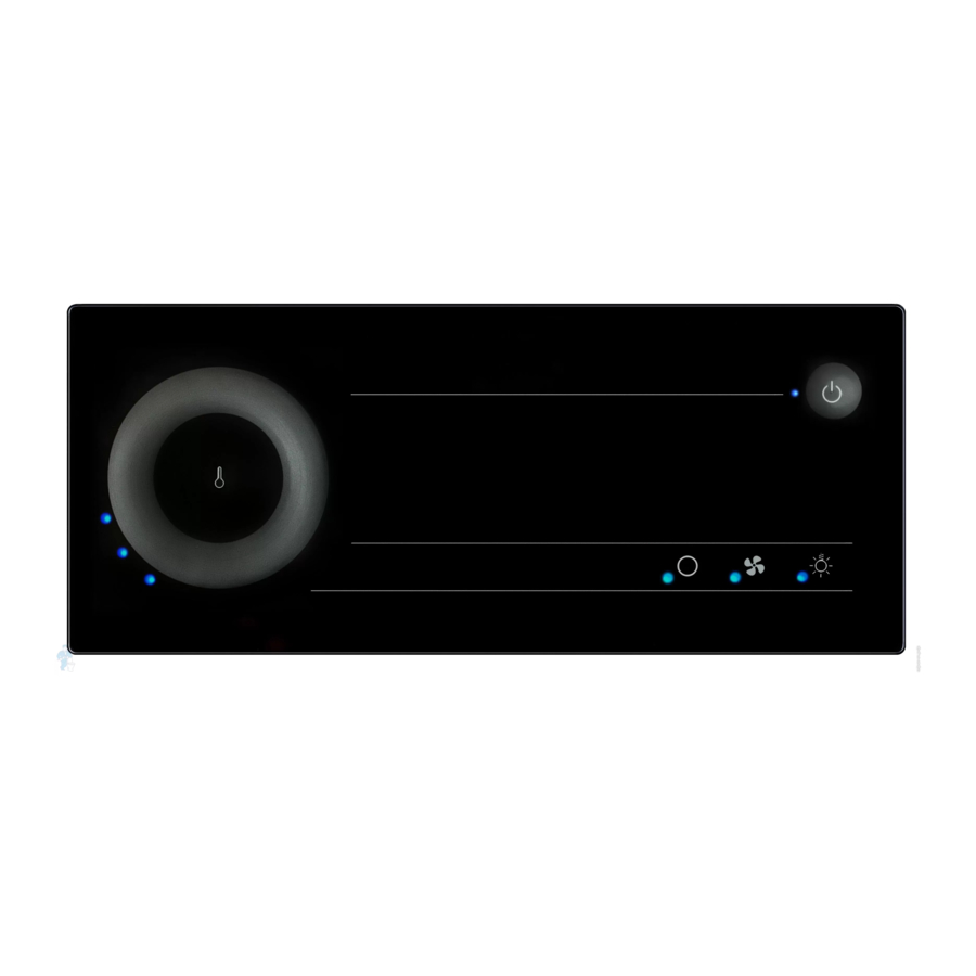
Instructions for use for the user p. 27/40 9. Operating elements 9.1. On the power unit A ON/OFF switch B Light switch 9.2. On the operating unit Operation LED Fan LED ON/OFF button Additional devices symbol Power level display Additional devices LED Light symbol Temperature symbol Light LED... -
Page 28: The Touch Wheel
Instructions for use for the user p. 28/40 9.3. The touch wheel The touch wheel can be used to set preset values for the sauna room tem- perature and for humidity. touch wheel. over the touch wheel. The preset values which you have set are indicated by the number of LEDs which light up on the LED wheel In two-sensor mode (with bench sensor, F2), in addition to the preset values, values measured in the sauna room (actual values) are displayed. -
Page 29: Power Level Display
Instructions for use for the user p. 29/40 9.5. Power level display If the dimmer switch function is activated for the device (see 8. Starting up), you can adjust the power of the light and the fan from power level 1 to power level 8. -
Page 30: Operation
Instructions for use for the user p. 30/40 10. Operation 10.1. Switching on the light on the power unit (cleaning lights) The light in the sauna room can be switched on and off at the power unit inde- pendently of the ON/OFF switch A. To switch the light on or off on the power unit, press the light switch B. -
Page 31: Starting The Sauna
Instructions for use for the user p. 31/40 10.4. Starting the sauna 1. Press the temperature symbol in the middle of the touch wheel The sauna heater switches on. 2. Use the touch wheel to set the preferred temperature. The LED wheel shows the preset temperature for a few seconds. -
Page 32: Switching Off The Additional Device
Instructions for use for the user p. 32/40 When the dimmer switch function is activated When the dimmer switch function for the additional output is activated, the power for the additional device can be set to any level between level 1 to level 7. 1. -
Page 33: Switching On The Light
Instructions for use for the user p. 33/40 10.8. Switching on the light When the dimmer switch function is activated When the dimmer function for the light is activated, the power for the light can be set to any level between level 1 to level 8. 1. -
Page 34: Switching On The Fan
Instructions for use for the user p. 34/40 10.10. Switching on the fan When the dimmer switch function is activated When the dimmer switch function for the fan is activated, the power for the fan can be set to any level between level 1 to level 8. 1. -
Page 35: Deactivating The Operating Unit
Instructions for use for the user p. 35/40 10.12. Deactivating the operating unit Press the ON/OFF button for one second. LEDs and the LED wheel goes out. The operation LED lights up in red. The operating unit is in standby mode. 10.13. -
Page 36: Cleaning And Maintenance
Instructions for use for the user p. 36/40 11. Cleaning and maintenance 11.1. Cleaning ATTENTION! Damage to the unit The sauna control unit is protected against jets of water, however direct contact with water could still damage the unit. NEVER immerse the device in water. Never pour water over the device. -
Page 37: Troubleshooting
Instructions for use for the user p. 37/40 13. Troubleshooting Error messages The sauna control unit is equipped with diagnostic software which monitors system statuses at start-up and during operation. As soon as the diagnostic Errors are indicated by a recurring warning tone emitted by the power unit and on the operating unit. -
Page 38: Fuses
Installation instructions, only for experts p. 38/40 14. Fuses Fuses for light, fan/power expansion and electronics as well as a spare fuse are located in the sauna control unit‘s connection area. These are 1A time delay micro fuses and can be ordered using the PRO-FUSE item number. -
Page 39: Technical Data
Instructions for installation and use p. 39/40 15. Technical data Ambient conditions Storage temperature: -25 °C to +70 °C Ambient temperature: -10 °C to +40 °C Relative humidity: max. 95% Dimensions Installation cut-out: 213 x 82 mm Power unit 307 x 175 x 52 mm Operating unit (with installation frame) 222 x 94 x 38 mm Operating unit (without installation frame) - Page 40 Instructions for installation and use p. 40/40 Light Contact rating: 100 W Fuse: 1A T Contact rating: 100 W Fuse: 1A T Setting ranges Temperature: 55 °C to 110 °C Thermal safety Heater sensor with excess temperature fuse (139 °C shut-off temperature) Automatic heating time limitation 6 h* Single-sensor mode or two-sensor mode for selection Connection cables...
Need help?
Do you have a question about the just sauna fin and is the answer not in the manual?
Questions and answers