Table of Contents
Advertisement
Available languages
Available languages
Quick Links
Sauna control unit
Pro D
INSTRUCTIONS FOR INSTALLATION AND USE
English
Pro D2
Pro D2 white
Pro D2i
Pro D2i white
Pro D3
D3 white
Pro D3i
D3i white
Version 12/20
1-041-288/PRO-D2
1-041-290/PRO-D2W
1-041-291/PRO-D2I
1-041-292/PRO-D2IW
1-041-293/PRO-D3
1-041-294/PRO-D3W
1-041-295/PRO-D3I
1-041-296/PRO-D2IW
Ident-Nr. 1-041-284
EN
DE
FR
IT
NL
SV
FI
RU
Advertisement
Chapters
Table of Contents

Subscribe to Our Youtube Channel
Related Manuals for Sentiotec Pro D2


Summary of Contents for Sentiotec Pro D2
- Page 1 Sauna control unit Pro D INSTRUCTIONS FOR INSTALLATION AND USE English Pro D2 1-041-288/PRO-D2 Pro D2 white 1-041-290/PRO-D2W Pro D2i 1-041-291/PRO-D2I Pro D2i white 1-041-292/PRO-D2IW Pro D3 1-041-293/PRO-D3 D3 white 1-041-294/PRO-D3W Pro D3i 1-041-295/PRO-D3I D3i white 1-041-296/PRO-D2IW Version 12/20 Ident-Nr. 1-041-284...
-
Page 2: Table Of Contents
Table of Contents 1. About this instruction manual 2. Important information for your safety 2.1. Intended use 2.2. Safety information for the installer 2.3. Safety information for the user 3. Product description 3.1. Specifications supplied 3.2. Optional accessories 3.3. Product functions 3.4. - Page 3 7. Terminal diagram 8. Commissioning 8.1. Setting the function selector switch 8.2. Settings on the technician menu 9. Controls 9.1. Control panel Pro D2 9.2. Control panel Pro D2i 9.3. Control panel Pro D3 9.4. Control panel Pro D3i 9.5.
- Page 4 10.6. Switching off sauna mode 10.7. Starting combi mode (only Pro D3/Pro D3i) 10.8. Switching off combi mode (only Pro D3/Pro D3i) 10.9. Starting additional output (only Pro D2i/Pro D3i) 10.10. Switching off additional output (optional, only Pro D2i/Pro D3i) 10.11. Switching on the light 10.12. Switching off the light 10.13. Starting the fan 10.14. Switching off the fan 10.15. Setting the preset time 10.16. Cancelling the preset time function 10.17.
- Page 5 14. Disposal 15. Troubleshooting 15.1. Error messages 15.2. Low-water display (only Pro D3/Pro D3i) 15.3. Fuses 16. Technical data 16.1. Power unit 16.2. Control panel Pro D2/Pro D2i/Pro D3/Pro D3i 16.3. Additional output control panel Pro D (optional)
-
Page 6: About This Instruction Manual
These installation and operating instructions can also be found in the downloads section of our website: www.sentiotec.com/downloads. Symbols used for warning notices In these instructions for installation and use, a warning notice located next to an activity indicates that this activity poses a risk. -
Page 7: Important Information For Your Safety
Instructions for installation and use p. 7/70 2. Important information for your safety The sauna control units of the Pro D series have been produced in accordance with the applicable safety rules and regulations. However, hazards may occur during use. Therefore adhere to the following safety information and the specific warning notices in the individual chapters. -
Page 8: Safety Information For The Installer
Instructions for installation and use p. 8/70 2.2. Safety information for the installer ● Installation may only be performed by a qualified electrician or similarly qualified person. ● Work on the sauna control unit may only be performed when the power has been disconnected. ● A fully disconnecting all-pole isolating device compliant with overvoltage category III must be fitted on-site. -
Page 9: Safety Information For The User
Instructions for installation and use p. 9/70 2.3. Safety information for the user ● The sauna control unit must not be used by children under 8 years old. ● The sauna control unit may be used by children above 8 years old, by persons with limited psychological, sensory or mental capabilities or by persons with lack of experience/knowledge only when:... -
Page 10: Product Description
Instructions for installation and use p. 10/70 3. Product description 3.1. Specifications supplied ● Operating unit (depending on version Pro D2/D2i/D3/D3i) ● Power unit ● Heater sensor with integrated overheat cut-out ● Sensor wires ● Installation material ● Wire jumper for bridging terminals V1 and Wm for combi heaters without low-water shut-off 3.2. -
Page 11: Product Functions
3.3. Product functions Pro D2/Pro D2 white The sauna control unit Pro D2/Pro D2 white features the following functions: ● Regulation of sauna heaters with a heating output of up to 10.5 kW in the temperature range spanning 30 °C to 110 °C. - Page 12 Instructions for installation and use p. 12/70 Pro D2i/Pro D2i white Same functional scope as the Pro D2/Pro D2 white, however with further additions: ● Additional output Either for dimming (up to 500 W), switching (up to 3.5 kW) or regulating the sauna room temperature via the additional output.
- Page 13 Instructions for installation and use p. 13/70 Pro D3/Pro D3 white The sauna control unit Pro D3/Pro D3 white features the following functions: ● Regulation of combi heaters with a heating output of up to 10.5 kW and evaporator output of up to 3.5 kW in the temperature range spanning 30 °C to 110 °C and a humidity range spanning 0% to 100%.
- Page 14 We recommend using the following infra- red lamps: ● 1-027-780/ DIR-350-R, 1-027-845/WIR-350-R, 1-027-781/DIR-500-R, 1-027-846/WIR-500-R, 1-027-782/DIR-750-R, 1-027-847/WIR-750-R, 1-027-779/DIR-1300-R, 1-027-844/WIR-1300-R ● 1-027-785/ECO-350-R, 1-027-784/ECO-350-G, 1-027-788/ECO-500-R, 1-027-787/ECO-500-G, 1-027-790/ECO-750-R Pro D2 (white) Pro D2i (white) Pro D3 (white) Pro D3i (white) Fig. 1 Overview of Pro D functions...
-
Page 15: Sauna Operating Modes
1-028-784/IR-WP-390, 1-028-938/IR-WP-510 ● 1-028-149/IR-WPHL-100, 1-028-941/IR-WPHL-175, 1-028-601/IR-WPHL-390, 1-027-885/IR-WPHL-510 3.4. Sauna operating modes The sauna control unit Pro D2/Pro D2i enables sauna mode operation. The sauna control unit Pro D3/Pro D3i provides two operating modes, sauna mode and combi mode. Sauna operating mode Dry heat is provided in sauna mode. -
Page 16: Sensor Operating Modes
Instructions for installation and use p. 16/70 3.5. Sensor operating modes The sauna control units of the Pro D series can be operated with one or two sensors. A temperature sensor (bench sensor F2) or a humidity sensor (FTS2, only Pro D3/Pro D3i) can be used as the second sensor. Single-sensor mode (F1) The single-sensor mode is activated at the factory. - Page 17 Instructions for installation and use p. 17/70 Two-sensor mode with bench sensor (F2) Two-sensor mode must be activated using the function selection switch (see “Activating two-sensor operation” on page 36). In two-sensor operation with bench sensor, a second temperature sensor (bench sensor) is installed above the rear sauna bench.
-
Page 18: Installation
Installation instructions, for professionals only p. 18/70 4. Installation 4.1. Installing the power supply unit ATTENTION! Damage to the unit The sauna control unit is protected against splashing water, however direct contact with water could still damage the unit. ● Install the sauna control unit in a dry place at which a maximum humidity of 95% is not exceeded. - Page 19 Installation instructions, for professionals only p. 19/70 To install the sauna control unit, perform the following steps: 1. Screw two cross-head screws (16 mm) into the wall of the sauna at a height of approx. 1.70 m and leaving a protruding length of 7 mm. The two screws must be placed at a distance of 145 mm from each other (see Fig.
-
Page 20: Installing The Control Panel
Installation instructions, for professionals only p. 20/70 4.2. Installing the control panel The control panel 2 is installed on the cabin wall at a maximum distance of 10 metres from the power supply unit 1 (see Fig. 4). Installation requires the use of a standard jigsaw, for example, to cut out the recess for the control unit. - Page 21 Installation instructions, for professionals only p. 21/70 1. Cut out the 70 x 65 or 60 x 48 mm recess using a jigsaw, for example (see Fig. 5 and Fig. 6). 2. Provide cable guides for the connecting cables. 3. Screw the housing to the cabin wall through the hole with the 4 or 2 wood screws enclosed.
- Page 22 Installation instructions, for professionals only p. 22/70 4. The front panel of the control unit is inserted with slight pressure into the hous- ing. Ensure that the lower catches engage noticeably. Fig. 7 In- stalling the control panel 5. Connect the 4-pin connector to the RJ11 socket on the control unit.
-
Page 23: Installing The Heater Sensor F1 With Overheat Cut-Out
Installation instructions, for professionals only p. 23/70 4.3. Installing the heater sensor F1 with overheat cut-out Observe the following points when installing the heater sensor: ● The heater sensor must be installed on the rear of the heater, above the mid- dle of the sauna heater. -
Page 24: Installing Bench Sensor F2 (Optional)
Installation instructions, for professionals only p. 24/70 4.4. Installing bench sensor F2 (optional) The bench sensor must be installed on the wall of the sauna room, above the rear bench seat. A clearance of approx. 15 cm from the roof of the sauna room must be maintained. -
Page 25: Installing Foil Sensor Fts2 (Optional, Only Pro D2I/Pro D3I)
Installation instructions, for professionals only p. 25/70 4.6. Installing foil sensor FTS2 (optional, only Pro D2i/Pro D3i) If one of the following infra-red heater panels is connected to an additional output, the foil sensor 1-014-445/P-ISX-FF must be used: ● 1-028-348/IR-WP-100 ●... -
Page 26: Electrical Connection
Installation instructions, for professionals only p. 26/70 5. Electrical connection ATTENTION! Damage to the unit ● The sauna control unit may only be used for operating and controlling 3 heat- ing circuits with a maximum heating capacity of 3.5 kW per heating circuit. The maximum evaporator output (only Pro D3/Pro D3i) is 3.5 kW. -
Page 27: Connecting The Power Supply Cable, Heater And Evaporator
Installation instructions, for professionals only p. 27/70 Observe the following points when connecting the power to the sauna control unit: ● Installation may only be performed by a qualified electrician or similarly quali- fied person. Please observe that in the event of a guarantee claim, a copy of the bill from the electrician performing the work must be presented. ●... -
Page 28: Connecting The Control Panel
Installation instructions, for professionals only p. 28/70 5.2. Connecting the control panel 1. Feed the connection cable for the control panel through the cable gland 4 into the low-voltage connection area 1. 2. Connect the plug of the RJ-10 cable to the connection socket h. The sauna control units of the Pro D series enable operation of up to 2 Pro D control panels and an additional output control panel on one power supply unit. -
Page 29: Connecting The Light
Installation instructions, for professionals only p. 29/70 5.3. Connecting the light 1. Feed the light cable through the cable gland b into the connection area for 230 V/400 V f. 2. Connect the light cable to the terminal strip d in accordance with the terminal diagram. -
Page 30: Connecting The Power Booster (Optional)
Installation instructions, for professionals only p. 30/70 5.6. Connecting the power booster (optional) 1. Feed the cable for the power booster through the cable gland a into the connection area for 230 V/400 V g. 2. Connect the cable for the power booster to the terminal strip e in accordance with the connection diagram. -
Page 31: Connecting Foil Sensor (Optional, Only Pro D2I/Pro D3I)
Installation instructions, for professionals only p. 31/70 5.10. Connecting foil sensor (optional, only Pro D2i/Pro D3i) 1. Feed the wires for the sensor through the cable gland 4 into the low-voltage connection area 1. 2. Connect the sensor cables for the sensor to the terminals labelled “FF” in terminal strip 2. -
Page 32: Status Output
Installation instructions, for professionals only p. 32/70 5.13. Status output Any electrical device can be connected to the status output terminal which is suitable for 24 V DC voltage and draws a current no greater than 200 mA. Make sure the polarity is correct when connecting a device. If LEDs are used, a suit- able series resistor must be used. - Page 33 Installation instructions, for professionals only p. 33/70 Switch on the sauna control unit. ► A recurring warning tone sounds, “4F1” appears in the display. ► The control unit switches off the heater. g. Switch off the sauna control unit. h. Reconnect the white wire for the heater sensor. 3. Check the phase circuit for sauna mode L1, L2, L3 is connected to U, V, W. 4.
-
Page 34: Terminal Diagram
Installation instructions, for professionals only p. 34/70 7. Terminal diagram... -
Page 35: Commissioning
Installation instructions, for professionals only p. 35/70 8. Commissioning 8.1. Setting the function selector switch The function selection switch in the low-voltage connection area allows a variety of product functions to be activated. The figure at the right shows the standard setting for the function selection switch. - Page 36 Installation instructions, for professionals only p. 36/70 Activating/deactivating phase alignment Phase alignment is activated or deactivated using the function selection switch 3. ● The function selection switch 3 is set to the ON position as standard. Phase alignment is therefore activated. ●...
- Page 37 Installation instructions, for professionals only p. 37/70 Selecting sensor for room temperature regulation with additional output (only Pro D2i/Pro D3i) For room temperature regulation using additional output (see “Room tempera- ture control with the additional output” on page 53) the sensor for the regulation can be selected with the function selection switch 6.
-
Page 38: Settings On The Technician Menu
Installation instructions, for professionals only p. 38/70 8.2. Settings on the technician menu Opening the technician menu Additional settings can be made on the technician menu. To access the techni- cian menu, perform the following steps: 1. Switch on the power supply unit. Press the On/Off button F. ► The sauna control unit is in stand-by mode. ►... - Page 39 Installation instructions, for professionals only p. 39/70 Activating evaporator single mode (only Pro D3/Pro D3i) The evaporator is factory set so that it can only be operated together with the heating system. To operate the evaporator on its own without the heating system, this function must be activated.
- Page 40 Installation instructions, for professionals only p. 40/70 Changing the light dimming characteristic Because incandescent bulbs and LEDs react differently to the dimming function, it is possible to select the dimming characteristic according to the light system used. Perform the following steps: 1. Open the technician menu (see page 38). 2. Select “dl” by pressing the mode button D. 3.
- Page 41 Installation instructions, for professionals only p. 41/70 Setting the fan operating mode The fan can either be modulated or switched on and off. The dimmer switch function for the fan is activated as standard. If you wish to deactivate the dimmer switch function for the fan, perform the following steps: 1. Open the technician menu (see page 38). 2.
- Page 42 Installation instructions, for professionals only p. 42/70 Activating the simultaneous display of the temperature and the humidity (only Pro D3/Pro D3i) To activate simultaneous display (automatic switching between the temperature and humidity display) of the temperature and humidity, carry out the following steps: 1.
- Page 43 Installation instructions, for professionals only p. 43/70 Setting mode of the additional output (only Pro D2i/Pro D3i) Two different modes are available for the additional output: 1. Intensity regulation 2. Room temperature regulation Perform the following steps to switch between the two modes: 1. Open the technician menu (see page 38). 2.
- Page 44 Installation instructions, for professionals only p. 44/70 Set foil operating mode with temperature control (only Pro D2i/Pro D3i) Here you can specify that if the temperature control is set (see “Set operating mode of auxiliary output-lr”on page 43 ), the auxiliary output remains in temperature control mode even when the sauna heater is switched on.
-
Page 45: Controls
Instructions for use for the user p. 45/70 9. Controls 9.1. Control panel Pro D2 9.2. Control panel Pro D2i... -
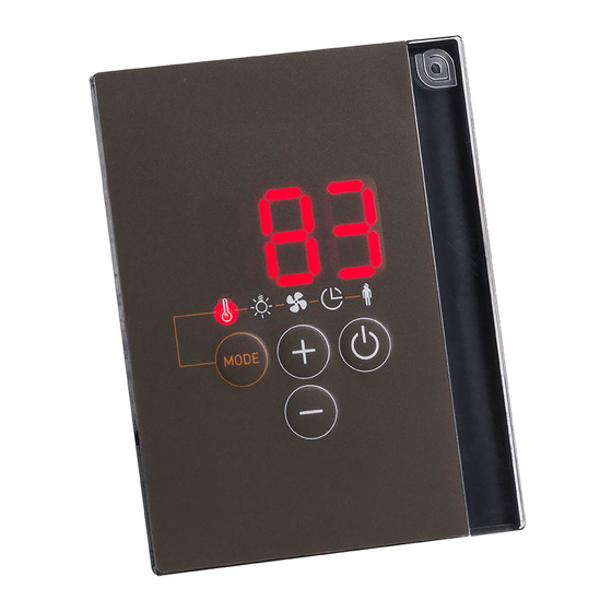
Page 46: Control Panel Pro D3
Instructions for use for the user p. 46/70 9.3. Control panel Pro D3 9.4. Control panel Pro D3i Display Temperature Humidity (only Pro D3/Pro D3i) preset time Additional output (only Pro D2i/Pro D3i) User programs Light On/Off button Minus button Plus button Mode button... -
Page 47: Additional Output Control Panel Pro D (Optional)
Instructions for use for the user p. 47/70 9.5. Additional output control panel Pro D (optional) On/Off button Standby for remote operation display Plus button Intensity display Minus button 9.6. Power unit F On/Off switch E Light switch... -
Page 48: Operation
Instructions for use for the user p. 48/70 10. Operation 10.1. Switching on the light on the power supply unit (cleaning lights) The light in the sauna room can be switched on and off at the power supply unit independently of the On/Off switch F. ● To switch the light on or off on the power supply unit, press the light switch E. If the light switch E is switched on, the sauna room light will operate at full power. If you wish to dim the light using the control panel, switch off the light switch E. -
Page 49: Activating The Control Panel
Instructions for use for the user p. 49/70 10.3. Activating the control panel The control unit can be started with the last used settings for temperature, humid- ity* and light or with the standard settings. ● For activation with the last used settings, press the On/Off button A for one second. ►... -
Page 50: Starting Sauna Mode
Instructions for use for the user p. 50/70 10.5. Starting sauna mode 1. Select the temperature symbol 5 by pressing the mode button D. Then briefly press the On/Off button A. ► The sauna heater switches on. 2. Set the desired temperature with the plus button B and the minus button C. ►... -
Page 51: Starting Combi Mode (Only Pro D3/Pro D3I)
Instructions for use for the user p. 51/70 10.7. Starting combi mode (only Pro D3/Pro D3i) 1. Select the temperature symbol 5 by pressing the mode button D. Then briefly press the On/Off button A. ► The sauna heater switches on. 2. Set the desired temperature with the plus button B and the minus button C. ►... -
Page 52: Starting Additional Output (Only Pro D2I/Pro D3I)
Instructions for use for the user p. 52/70 The evaporator (humidity function 6) can only be started when the sauna heater (temperature function 5) is switched on. The maximum humidity level which can be set depends on the temperature of the sauna. The higher the sauna temperature, the lower the maximum humidity level which can be set. - Page 53 Instructions for use for the user p. 53/70 Intensity regulation when the dimmer switch function is activated When the dimmer switch function for the additional output is activated, the power for the additional device can be set to a scale of 1 to 7. 7 corresponds to full power. 1.
-
Page 54: Switching Off Additional Output (Optional, Only Pro D2I/Pro D3I)
Instructions for use for the user p. 54/70 Using the optional control panel “Additional output control panel Pro D” The optional control panel enables the switching on and off of the additional output as well as the dimming or changing of the temperature. The additional output can only be activated if the control unit is already switched on. 1. -
Page 55: Switching On The Light
Instructions for use for the user p. 55/70 10.11. Switching on the light When the dimmer switch function is activated When the dimmer function for the light is activated, the power for the light can be set to any level between level 0 to level 100. At 0, the light is switched off. 100 corresponds to full power. 1. -
Page 56: Starting The Fan
Instructions for use for the user p. 56/70 10.13. Starting the fan When the dimmer switch function is activated When the dimmer switch function for the fan is activated, the power for the fan can be set to a scale of 0 to 100. 100 corresponds to full power. 1. -
Page 57: Setting The Preset Time
Instructions for use for the user p. 57/70 10.15. Setting the preset time You can set the preset time to the minute. The maximum preset time totals 6 hours. WARNING! Risk of fire Combustible objects that are placed on the heater will ignite and cause fires. -
Page 58: Cancelling The Preset Time Function
Instructions for use for the user p. 58/70 10.16. Cancelling the preset time function ● Press the On/Off button A, to cancel the preset function. ► The preset time countdown is cancelled. ► The control unit starts immediately with the previously set functions. 10.17. Setting the duration When you start the sauna, you can already determine how long the sauna is to operate. -
Page 59: Activating Standby For Remote Operation
Instructions for use for the user p. 59/70 10.18. Activating standby for remote operation EN 60335-2-53 specifies that sauna control units with a remote start function must be set manually to “Standby for remote operation” mode. This activation must take place again after each remote start and stop procedure. Perform the following steps: 1. -
Page 60: Cancelling The Post-Drying Program (Only Pro D3/Prod3I)
Instructions for use for the user p. 60/70 10.20. Cancelling the post-drying program (only Pro D3/ProD3i) After the combi-mode, the post-drying program is started automatically. This in- volves heating the sauna room to 80 °C with the fan running for 30 minutes. In the display 1, the text “dry” is displayed and the temperature symbol flashes. -
Page 61: User Programs
● Additional output (intensity or room temperature regulation) ● Light ● Fan 11.1. Preset user programs The following user programs are already predefined. The “humidity” value is not included in the Pro D2 and Pro D2i control units. The “additional output” value is not included in the Pro D2 and Pro D3 control units. Light User Tempera-... -
Page 62: Accessing User Programs
Instructions for use for the user p. 62/70 11.2. Accessing user programs 1. Select the user program symbol 4 by pressing the mode button D. ► The user program symbol lights up. 2. Select the desired user program (1 - 5) with the plus button B and the minus button C. - Page 63 Instructions for use for the user p. 63/70 Perform the following steps to save the settings in the table above in user program 2: 1. Select the temperature symbol 5 by pressing the mode button D. Then briefly press the On/Off button A. ► The sauna heater switches on. 2.
-
Page 64: The Eco-Function
Instructions for use for the user p. 64/70 12. The Eco-function The Eco-function allows you to save energy in breaks between sauna sessions. When the Eco-function is activated, the connected appliances run with reduced power. You can choose between a 20, 40 or 60-minute sauna break. The sauna heater and the evaporator are switched on again before the end of the break. -
Page 65: Cleaning And Maintenance
Instructions for use for the user p. 65/70 13. Cleaning and maintenance 13.1. Cleaning ATTENTION! Damage to the unit The sauna control unit is protected against splashing water, however direct contact with water could still damage the unit. ● Never immerse the appliance in water. ●... -
Page 66: Troubleshooting
Installation instructions, for professionals only p. 66/70 15. Troubleshooting 15.1. Error messages The sauna control unit is equipped with diagnostic software which monitors system statuses when it switches on and during operation. As soon as the diagnostic software identifies an error, the sauna control unit switches the sauna heater off. Errors are indicated by a recurring warning tone and by flashing of the symbols 2 to 8. Furthermore, the error number appears in the additional display 1. Switch the sauna control unit off using the On/Off switch 6 and rectify the error before switching the sauna control unit on again. -
Page 67: Low-Water Display (Only Pro D3/Pro D3I)
Instructions for use for the user p. 67/70 15.2. Low-water display (only Pro D3/Pro D3i) The sauna control unit features an automatic low-water cut-out feature which is active in combi mode, as long as your combi heater supports it. If the water tank in the evaporator is empty, this is indicated by a recurring warn- ing tone and the message “FIL”... -
Page 68: Technical Data
Instructions for installation and use p. 68/70 16. Technical data 16.1. Power unit Ambient conditions Storage temperature: -25 °C to +70 °C Ambient temperature: -10 °C to +40 °C Relative humidity: max. 95% Sauna control unit Dimensions (W x H x D): 307 x 175 x 57 mm Switched voltage/three-phase 3N: 400 V AC... - Page 69 Instructions for installation and use p. 69/70 Setting ranges Temperature: 30 °C to 110 °C Humidity: 0% to 100% The maximum humidity level which can be set depends on the temperature of the sauna. The higher the sauna temperature, the lower the maximum humidity level which can be set.
-
Page 70: Control Panel Pro D2/Pro D2I/Pro D3/Pro D3I
Instructions for installation and use p. 70/70 16.2. Control panel Pro D2/Pro D2i/Pro D3/Pro D3i Ambient conditions Storage temperature: -25 °C to +70 °C Ambient temperature: 0 °C to +100 °C Relative humidity: max. 99% non-condensing Sauna control unit Dimensions (W x H x D):... - Page 71 Saunasteuerung Pro D MONTAGE- UND GEBRAUCHSANWEISUNG Deutsch Pro D2 1-041-288 / PRO-D2 Pro D2 white 1-041-290 / PRO-D2W Pro D2i 1-041-291 / PRO-D2I Pro D2i white 1-041-292 / PRO-D2IW Pro D3 1-041-293 / PRO-D3 Pro D3 white 1-041-294 / PRO-D3W...
- Page 72 Inhaltsverzeichnis 1. Zu dieser Anleitung 2. Wichtige Hinweise zu Ihrer Sicherheit 2.1. Bestimmungsgemäßer Gebrauch 2.2. Sicherheitshinweise für den Monteur 2.3. Sicherheitshinweise für den Anwender 3. Produktbeschreibung 3.1. Lieferumfang 3.2. Optionales Zubehör 3.3. Produktfunktionen 3.4. Sauna-Betriebsarten 3.5. Fühler-Betriebsarten 4. Montage 4.1. Leistungsteil montieren 4.2.
- Page 73 6. Prüfungen durchführen 7. Anschlussplan 8. Inbetriebnahme 8.1. Einstellung der Funktionswahlschalter 8.2. Einstellungen im Technikermenü 9. Bedienelemente 9.1. Bedienteil Pro D2 9.2. Bedienteil Pro D2i 9.3. Bedienteil Pro D3 9.4. Bedienteil Pro D3i 9.5. Zusatzausgang Bedienteil Pro D (optional) 9.6.
- Page 74 10.6. Sauna-Betrieb ausschalten 10.7. Kombi-Betrieb starten (nur Pro D3 / Pro D3i) 10.8. Kombi-Betrieb ausschalten (nur Pro D3 / Pro D3i) 10.9. Zusatzausgang starten (nur Pro D2i / Pro D3i) 10.10. Zusatzausgang ausschalten (nur Pro D2i / Pro D3i) 10.11. Licht einschalten 10.12.
- Page 75 14. Entsorgung 15. Problemlösung 15.1. Fehlermeldungen 15.2. Wassermangelanzeige (nur Pro D3 / Pro D3i) 15.3. Sicherungen 16. Technische Daten 16.1. Leistungsteil 16.2. Bedienteil Pro D2 / Pro D2i / Pro D3 / Pro D3i 16.3. Zusatzausgang Bedienteil Pro D (optional)
-
Page 76: Zu Dieser Anleitung
Nähe der Saunasteuerung auf. So können Sie jederzeit Informationen zu Ihrer Sicherheit und zur Bedienung nachlesen. Sie finden diese Montage- und Gebrauchsanweisung auch im Download- bereich unserer Webseite auf www.sentiotec.com/downloads. Symbole in Warnhinweisen In dieser Montage- und Gebrauchsanweisung ist vor Tätigkeiten, von denen eine Gefahr ausgeht, ein Warnhinweis angebracht. -
Page 77: Wichtige Hinweise Zu Ihrer Sicherheit
Montage- und Gebrauchsanweisung S. 7/37 2. Wichtige Hinweise zu Ihrer Sicherheit Die Saunasteuerungen der Pro D Serie sind nach anerkannten sicherheitstechnischen Regeln gebaut. Dennoch können bei der Verwendung Gefahren entstehen. Befolgen Sie deshalb die folgen- den Sicherheitshinweise und die speziellen Warnhinweise in den einzelnen Kapiteln. -
Page 78: Sicherheitshinweise Für Den Monteur
Montage- und Gebrauchsanweisung S. 8/37 2.2. Sicherheitshinweise für den Monteur ● Die Montage darf nur durch eine Elektrofachkraft oder eine ver- gleichsweise qualifizierte Person ausgeführt werden. ● Arbeiten an der Saunasteuerung dürfen nur im spannungsfreien Zustand durchgeführt werden. ● Es ist bauseits eine allpolige Trennvorrichtung mit voller Abschal- tung entsprechend der Überspannungskategorie III vorzusehen. -
Page 79: Sicherheitshinweise Für Den Anwender
Montage- und Gebrauchsanweisung S. 9/37 2.3. Sicherheitshinweise für den Anwender ● Die Saunasteuerung darf nicht von Kindern unter 8 Jahren ver- wendet werden. ● Die Saunasteuerung darf von Kindern über 8 Jahren, von Perso- nen mit verringerten psychischen, sensorischen oder mentalen Fähigkeiten und von Personen mit Mangel an Erfahrung und Wissen unter folgenden Bedingungen verwendet werden: –... -
Page 80: Produktbeschreibung
Montage- und Gebrauchsanweisung S. 10/37 3. Produktbeschreibung 3.1. Lieferumfang ● Bedienteil (je nach Ausführung Pro D2 / D2i / D3 / D3i) ● Leistungsteil ● Ofenfühler mit integrierter Übertemperatur-Sicherung ● Fühlerleitungen ● Montagematerial ● Drahtbrücke zur Überbrückung der Klemmen V1 und Wm für Kombiöfen ohne Wassermangel-Abschaltung 3.2. -
Page 81: Produktfunktionen
S. 11/37 3.3. Produktfunktionen Pro D2 / Pro D2 white Die Saunasteuerung Pro D2 / Pro D2 white verfügt über folgende Funktionen: ● Regeln von Saunaöfen mit einer Heizleistung bis 10,5 kW im Temperaturbe- reich von 30 °C bis 110 °C. - Page 82 Montage- und Gebrauchsanweisung S. 12/37 Pro D2i / Pro D2i white Funktionsumfang wie Pro D2 / Pro D2 white jedoch zusätzlich: ● Zusatzausgang Wahlweise Dimmen (bis 500 W), Schalten (bis 3,5 kW) oder Regeln der Kabinentemperatur über den Zusatzausgang. Zusatzausgang hat keine Übertemperatursicherung. Deshalb dürfen am Zusatzausgang nur eigensichere Geräte betrieben werden.
- Page 83 Montage- und Gebrauchsanweisung S. 13/37 Pro D3 / Pro D3 white Die Saunasteuerung Pro D3 / Pro D3 white verfügt über folgende Funktionen: ● Regeln von Kombi-Saunaöfen mit einer Heizleistung bis 10,5 kW und einer- Verdampferleistung bis 3,5 kW im Temperaturbereich von 30 °C bis 110 °C und einem Feuchtebereich von 0 bis 100 %.
- Page 84 / WIR-750-R, 1-027-779 / DIR-1300-R, 1-027-844 / WIR-1300-R ● 1-027-785 / ECO-350-R, 1-027-784 / ECO-350-G, 1-027-788 / ECO-500-R, 1-027-787 / ECO-500-G, 1-027-790 / ECO-750-R – Wenn an den Zusatzausgang eine der folgenden Infrarot-Wärmeplatten Pro D2 (white) Pro D2i (white) Pro D3 (white) Pro D3i (white) Abb.1...
-
Page 85: Sauna-Betriebsarten
● 1-028-149 / IR-WPHL-100, 1-028-941 / IR-WPHL-175, 1-028-601 / IR-WPHL-390, 1-027-885 / IR-WPHL-510 3.4. Sauna-Betriebsarten Die Saunasteuerung Pro D2 / Pro D2i ermöglicht den Saunabetrieb. Die Saunasteu- erung Pro D3 / Pro D3i ermöglicht zwei Betriebsarten, Sauna- und Kombi-Betrieb. Sauna-Betrieb Im Sauna-Betrieb steht trockene Wärme zur Verfügung. -
Page 86: Fühler-Betriebsarten
Montage- und Gebrauchsanweisung S. 16/37 3.5. Fühler-Betriebsarten Die Saunasteuerungen der Pro D Serie können mit einem oder mit zwei Fühlern betrieben werden. Als zweiter Fühler kann ein Temperaturfühler (Bankfühler F2) oder ein Feuchte-Temperaturfühler (FTS2, nur Pro D3 / Pro D3i) verwendet werden. Ein-Fühlerbetrieb (F1) Der Ein-Fühlerbetrieb ist ab Werk aktiviert. - Page 87 Montage- und Gebrauchsanweisung S. 17/37 Zweifühler-Betrieb mit Bankfühler (F2) Der Zwei-Fühlerbetrieb muss mittels Funktionswahlschalter aktiviert werden (siehe „Zwei-Fühlerbetrieb aktivieren“ auf Seite 36). Im Zwei-Fühlerbetrieb mit Bankfühler wird ein zweiter Temperaturfühler (Bank- fühler) oberhalb der hinteren Saunabank montiert. Die Saunasteuerung zeigt als Ist-Temperatur jene Temperatur an, die vom Bankfühler gemessen wird.
-
Page 88: Montage
Montageanweisung – nur für Fachpersonal S. 18/37 4. Montage 4.1. Leistungsteil montieren ACHTUNG! Schäden am Gerät Die Saunasteuerung ist spritzwassergeschützt, trotzdem kann direkter Kontakt mit Wasser das Gerät beschädigen. ● Montieren Sie die Saunasteuerung an einem trockenen Ort, an dem eine maximale Luftfeuchte von 95% nicht überschritten wird. - Page 89 Montageanweisung – nur für Fachpersonal S. 19/37 Zur Montage der Saunasteuerung führen Sie folgende Schritte durch: 1. Drehen Sie zwei Kreuzschlitzschrauben (16 mm) in ca. 1,70 m Höhe bis zu einem Abstand von 7 mm in die Saunawand ein. Die beiden Schrauben müssen einen Abstand von 145 mm zueinander haben (siehe Abb.2).
-
Page 90: Bedienteil Montieren
Montageanweisung – nur für Fachpersonal S. 20/37 4.2. Bedienteil montieren Das Bedienteil 2 wird an der Kabinenwand im maximalen Abstand von 10 Metern zum Leistungsteil 1 montiert (siehe Abb.4). Für die Montage wird beispielsweise eine handelsübliche Stichsäge benötigt um die Ausnehmung für das Bedienteil zu schneiden. Das Bedienteil kann sowohl in der Kabine als auch außerhalb der Kabine montiert werden. - Page 91 Montageanweisung – nur für Fachpersonal S. 21/37 1. Mit beispielsweise einer Stichsäge die Ausnehmung 70 x 65 oder 60 x 48 mm schneiden (siehe Abb.5 und Abb.6). 2. Leitungsführungen für die Verbindungsleitungen vorsehen. 3. Gehäuse durch die Bohrung mit den 4 oder 2 beiligenden Holzschrauben an die Kabinenwand schrauben.
- Page 92 Montageanweisung – nur für Fachpersonal S. 22/37 4. Die Frontplatte des Bedienteils wird mit leichtem Druck in das Gehäuse eingesteckt. Achten Sie darauf, dass der untere Befestigungshaken spürbar einrastet. Abb.7 Montage Bedienteil 5. Verbinden Sie den 4-poligen Stecker mit der RJ11 Buchse des Bedienteils.
-
Page 93: Ofenfühler F1 Mit Übertemperatur-Sicherung Montieren
Montageanweisung – nur für Fachpersonal S. 23/37 4.3. Ofenfühler F1 mit Übertemperatur-Sicherung montieren Beachten Sie bei der Montage des Ofenfühlers folgende Punkte: ● Der Ofenfühler ist an der Ofen-Rückwand oberhalb der Mitte des Saunaofens zu montieren. Dabei ist ein Abstand von zirka 15 cm zur Kabinendecke ein- zuhalten. -
Page 94: Bankfühler F2 Montieren (Optional)
Montageanweisung – nur für Fachpersonal S. 24/37 4.4. Bankfühler F2 montieren (optional) Der Bankfühler ist an der Kabinenwand oberhalb der hinteren Sitzbank zu mon- tieren. Dabei ist ein Abstand von zirka 15 cm zur Kabinendecke einzuhalten. Zur Montage des Bankfühlers führen Sie folgende Schritte durch: 1. -
Page 95: Folien-Fühler Montieren (Optional, Nur Pro D2I / Pro D3I) Montieren
Montageanweisung – nur für Fachpersonal S. 25/37 4.6. Folien-Fühler montieren (optional, nur Pro D2i / Pro D3i) montieren Wenn an den Zusatzausgang eine der folgenden Infrarot-Wärmeplatten ange- schlossen wird, muss der Folienfühler 1-014-445 / P-ISX-FF verwendet werden: ● 1-028-348 / IR-WP-100 ●... -
Page 96: Elektrischer Anschluss
Montageanweisung – nur für Fachpersonal S. 26/37 5. Elektrischer Anschluss ACHTUNG! Schäden am Gerät ● Die Saunasteuerung darf nur zum Steuern und Regeln von 3 Heizkreisen mit einer Heizleistung von max. 3,5 kW pro Heizkreis eingesetzt werden. Die maximale Verdampferleistung (nur Pro D3 / Pro D3i) beträgt 3,5 kW. Die ma- ximale Leistung des Zusatzausgangs (nur Pro D2i / Pro D3i) beträgt 3,5 kW. -
Page 97: Versorgungsleitung, Ofen Und Verdampfer Anschließen
Montageanweisung – nur für Fachpersonal S. 27/37 Beachten Sie beim elektrischen Anschluss der Saunasteuerung folgende Punkte: ● Die Montage darf nur durch eine Elektrofachkraft oder eine vergleichsweise qualifizierte Person ausgeführt werden. Bitte beachten Sie, dass im Falle eines Garantieanspruches eine Kopie der Rechnung des ausführenden Elektrofachbetriebes vorzulegen ist. ●... -
Page 98: Bedienteil Anschließen
Montageanweisung – nur für Fachpersonal S. 28/37 5.2. Bedienteil anschließen 1. Führen Sie das Anschlusskabel des Bedienteils durch die Kabeldurchfüh- rung 4 in den Anschlussbereich für Kleinspannung 1. 2. Stecken Sie den Stecker des RJ-10-Kabels in die Anschlussbuchse h. Die Saunasteuerungen der Pro D Serie ermöglichen den Betrieb von bis zu 2 Pro D Bedienteilen und einem Zusatzausgang Bedienteil, an einem Leistungsteil. -
Page 99: Licht Anschließen
Montageanweisung – nur für Fachpersonal S. 29/37 5.3. Licht anschließen 1. Führen Sie die Lichtleitung durch die Kabeldurchführung b in den An- schlussbereich für 230 V / 400 V f. 2. Schließen Sie die Lichtleitung gemäß dem Anschlussplan an die Klemmleis- te d an. -
Page 100: Leistungserweiterung (Optional) Anschließen
Montageanweisung – nur für Fachpersonal S. 30/37 5.6. Leistungserweiterung (optional) anschließen 1. Führen Sie die Leitung der Leistungserweiterung durch die Kabeldurchfüh- rung a in den Anschlussbereich für 230 V / 400 V f. 2. Schließen Sie die Leitung der Leistungserweiterung gemäß dem An- schlussplan an die Klemmleiste e an. -
Page 101: Folienfühler (Optional, Nur Pro D2I / Pro D3I) Anschließen
Montageanweisung – nur für Fachpersonal S. 31/37 5.10. Folienfühler (optional, nur Pro D2i / Pro D3i) anschließen 1. Führen Sie die Fühlerleitungen durch die Kabeldurchführung 4 in den Anschlussbereich für Kleinspannung 1. 2. Schließen Sie die Fühlerleitungen an die Klemmen mit der Beschriftung "FF" in der Klemmleiste 2 an. -
Page 102: Statusausgang
Montageanweisung – nur für Fachpersonal S. 32/37 5.13. Statusausgang An der Klemme für den Statusausgang kann jeder Verbraucher angeschlossen werden, der für eine Spannung von 24 Volt DC geeignet ist und nicht mehr als 200 mA Strom bezieht. Achten Sie beim Anschluss auf die richtige Polung. Bei der Verwendung von LEDs muss ein geeigneter Vorwiderstand verwendet werden. - Page 103 Montageanweisung – nur für Fachpersonal S. 33/37 Schalten Sie die Saunasteuerung ein. ► Ein wiederkehrender Warnton ertönt, im Display wird "4F1" angezeigt. ► Die Steuerung schaltet den Ofen ab. g. Schalten Sie die Sauansteuerung aus. h. Klemmen Sie die weiße Ofenfühler-Leitung wieder an. 3.
-
Page 104: Anschlussplan
Montageanweisung – nur für Fachpersonal S. 34/37 7. Anschlussplan... -
Page 105: Inbetriebnahme
Montageanweisung – nur für Fachpersonal S. 35/37 8. Inbetriebnahme 8.1. Einstellung der Funktionswahlschalter Über die Funktionswahlschalter im Anschlussbereich für Kleinspannung können verschiedene Produktfunk- tionen aktiviert werden. Die Abbil- dung rechts zeigt die Standardein- stellung der Funktionswahlschalter. Beachten Sie, dass nach Ände- rungen die Steuerung für 10 Sek. - Page 106 Montageanweisung – nur für Fachpersonal S. 36/37 Phasenrollierung aktivieren/deaktivieren Die Phasenrollierung wird mit dem Funktionswahlschalter 3 aktiviert bzw. de- aktiviert. ● Standardmäßig befindet sich der Funktionswahlschalter 3 in ON-Position. Die Phasenrollierung ist damit aktiviert. ● Wenn Sie die Phasenrollierung deaktivieren möchten, bringen Sie den Funk- tionswahlschalter 3 in die OFF-Position.
- Page 107 Montageanweisung – nur für Fachpersonal S. 37/37 Fühler für Raumtemperaturregelung mit Zusatzausgang auswählen (nur Pro D2i / Pro D3i) Bei Raumtemperaturregelgung mittels Zusatzausgang (siehe „Raumtempera- turregelung des Zusatzausgangs“ auf Seite 53) kann mit dem Funktions- wahlschalter 6 der Fühler, für die Regelung, ausgewählt werden. ●...
-
Page 108: Einstellungen Im Technikermenü
Montageanweisung – nur für Fachpersonal S. 38/42 8.2. Einstellungen im Technikermenü Techniker-Menü aufrufen Im Techniker-Menü können weitere Einstellungen vorgenommen werden. Um ins Technikermenü zu gelangen, führen Sie folgende Schritte aus: 1. Schalten Sie das Leistungsteil ein. Drücken Sie dazu den Ein/Aus-Schalter F. ►... - Page 109 Montageanweisung – nur für Fachpersonal S. 39/42 Verdampfer-Single-Betrieb aktivieren (nur Pro D3 / Pro D3i) Werkseitig lässt sich der Verdampfer nur gemeinsam mit dem Heizsystem in Be- trieb nehmen. Um den Verdampfer alleine ohne Heizsystem betreiben zu können, muss diese Funktion aktiviert werden. Führen Sie dazu folgende Schritte durch: 1.
- Page 110 Montageanweisung – nur für Fachpersonal S. 40/42 Licht-Dimmkurve ändern Da Glühbirnen und LEDs unterschiedlich auf die Dimmfunktion reagieren, besteht die Möglichkeit die Dimmkurve entsprechend dem verwendeten Lichtsystem auszuwählen. Führen Sie folgende Schritte durch: 1. Rufen Sie das Techniker-Menü auf (siehe Seite 38). 2.
- Page 111 Montageanweisung – nur für Fachpersonal S. 41/42 Lüfter-Betriebsmodus einstellen Der Lüfter ist wahlweise dimmbar oder schaltbar. Standardmäßig ist die Dimm- funktion des Lüfters aktiviert. Wenn Sie die Dimmfunktion des Lüfters deaktivieren möchten, führen Sie folgende Schritte durch: 1. Rufen Sie das Techniker-Menü auf (siehe Seite 38). 2.
- Page 112 Montageanweisung – nur für Fachpersonal S. 42/42 Gleichzeitige Anzeige der Temperatur und des Feuchtewertes aktivieren (nur Pro D3 / Pro D3i) Um die gleichzeitige (automatischer Wechsel zwischen Anzeige der Temperatur und Feuchte) Anzeige von Temperatur und Feuchte zu aktivieren, führen Sie folgende Schritte durch: 1.
- Page 113 Montageanweisung – nur für Fachpersonal S. 43/70 Betriebsart des Zusatzausgangs einstellen (nur Pro D2i/Pro D3i) Für den Zusatzausgang stehen zwei verschiedene Betriebsarten zur Verfügung: 1. Intensitätsregelung 2. Raumtemperaturregelung Um zwischen den beiden Betriebsarten zu wechseln, führen Sie folgende Schritte durch: 1.
- Page 114 Montageanweisung – nur für Fachpersonal S. 44/70 Betriebsart Folienbetrieb mit Temperaturregelung einstellen (nur Pro D2i/Pro D3i) Hier kann festgelegt werden, dass der Zusatzausgang bei eingestellter Tem- peraturregelung (siehe „Betreibsart des Zusatzausgangs einstellen-Ir“ auf Seite 43) auch bei Zuschalten des Saunaofens im Betrieb Temperaturrege- lung bleibt.
-
Page 115: Bedienelemente De
Gebrauchsanweisung für den Anwender S. 45/70 9. Bedienelemente 9.1. Bedienteil Pro D2 9.2. Bedienteil Pro D2i... -
Page 116: Bedienteil Pro D3
Gebrauchsanweisung für den Anwender S. 46/70 9.3. Bedienteil Pro D3 9.4. Bedienteil Pro D3i Anzeige Temperatur Lüfter Feuchte (nur Pro D3 / Pro D3i) Vorwahlzeit Zusatzausgang (nur Pro D2i / Pro D3i) Benutzerprogramme Licht Ein/Aus-Taste Minus-Taste Plus-Taste Mode-Taste... -
Page 117: Zusatzausgang Bedienteil Pro D (Optional)
Gebrauchsanweisung für den Anwender S. 47/70 9.5. Zusatzausgang Bedienteil Pro D (optional) Ein/Aus-Taste Anzeige Standby für Fernwirken Plus-Taste Intensitätsanzeige Minus-Taste 9.6. Leistungsteil F Ein/Aus-Schalter E Lichtschalter... -
Page 118: Bedienung
Gebrauchsanweisung für den Anwender S. 48/70 10. Bedienung 10.1. Licht am Leistungsteil einschalten (Reinigungsbeleuchtung) Das Licht in der Saunakabine kann am Leistungsteil unabhängig vom Ein/Aus- Schalter F eingeschaltet und ausgeschaltet werden. ● Um das Licht am Leistungsteil einzuschalten bzw. auszuschalten, drücken Sie den Lichtschalter E. -
Page 119: Bedienteil Aktivieren
Gebrauchsanweisung für den Anwender S. 49/70 10.3. Bedienteil aktivieren Die Steuerung kann mit den zuletzt verwendeten Einstellungen für Temperatur, Feuchte* und Licht oder mit den Standardeinstellungen gestartet werden. ● Für das aktivieren mit den zuletzt verwendeten Einstellungen, drücken Sie für eine Sekunde die Ein/Aus-Taste A. ►... -
Page 120: Sauna-Betrieb Starten
Gebrauchsanweisung für den Anwender S. 50/70 10.5. Sauna-Betrieb starten 1. Wählen Sie durch drücken der Mode-Taste D das Temperatur-Symbol 5 aus. Drücken Sie anschließend kurz die Ein/Aus-Taste A. ► Der Saunaofen wird eingeschaltet. 2. Stellen Sie mit der Plus-Taste B und Minus-Taste C die gewünschte Tem- peratur ein. -
Page 121: Kombi-Betrieb Starten (Nur Pro D3 / Pro D3I)
Gebrauchsanweisung für den Anwender S. 51/70 10.7. Kombi-Betrieb starten (nur Pro D3 / Pro D3i) 1. Wählen Sie durch drücken der Mode-Taste D das Temperatur-Symbol 5 aus. Drücken Sie anschließend kurz die Ein/Aus-Taste A. ► Der Saunaofen wird eingeschaltet. 2. Stellen Sie mit der Plus-Taste B und Minus-Taste C die gewünschte Tem- peratur ein. -
Page 122: Zusatzausgang Starten (Nur Pro D2I / Pro D3I)
Gebrauchsanweisung für den Anwender S. 52/70 Der Verdampfer (Feuchtefunktion 6) lässt sich nur starten, wenn der Saunaofen (Temperaturfunktion 5) eingeschaltet ist. Dabei ist die ma- ximal einstellbare Soll-Feuchte von der Saunatemperatur abhängig. Je höher die Saunatemperatur, desto niedriger ist der maximal einstellbare Feuchtewert. - Page 123 Gebrauchsanweisung für den Anwender S. 53/70 Intensitätsregelung bei aktivierter Dimmfunktion Wenn die Dimmfunktion des Zusatzausgangs aktiviert ist, können Sie die Leistung des Zusatzgeräts auf einer Skala von 1 bis 7 einstellen. Der Wert 7 entspricht der vollen Leistung. 1. Wählen Sie durch drücken der Mode-Taste D das Zusatzausgang-Symbol 7 aus.
-
Page 124: Zusatzausgang Ausschalten (Nur Pro D2I / Pro D3I)
Gebrauchsanweisung für den Anwender S. 54/70 Verwenden des optionalen Bedienteils „Zusatzausgang Bedienteil Pro D“ Das optionale Bedienteil ermöglicht das Ein- und Ausschalten des Zusatzaugangs sowie das Dimmen oder die Änderung der Temperatur. Der Zusatzaugsgang kann nur aktiviert werden, wenn die Steuerung bereits eingeschalten ist. 1. -
Page 125: Licht Einschalten
Gebrauchsanweisung für den Anwender S. 55/70 10.11. Licht einschalten Bei aktivierter Dimmfunktion Wenn die Dimmfunktion des Lichts aktiviert ist, können Sie die Leistung des Lichts von Stufe 0 bis Stufe 100 einstellen. Beim Wert 0 ist das Licht ausgeschaltet. Der Wert 100 entspricht der vollen Leistung. 1. -
Page 126: Lüfter Starten
Gebrauchsanweisung für den Anwender S. 56/70 10.13. Lüfter starten Bei aktivierter Dimmfunktion Wenn die Dimmfunktion des Lüfters aktiviert ist, können Sie die Leistung des Lüfters auf einer Skala von 0 bis 100 einstellen. Der Wert 100 entspricht der vollen Leistung. 1. -
Page 127: Vorwahlzeit Einstellen
Gebrauchsanweisung für den Anwender S. 57/70 10.15. Vorwahlzeit einstellen Sie können die Vorwahlzeit minutengenau einstellen. Die maximale Vorwahlzeit beträgt 6 Stunden. WARNUNG! Brandgefahr Brennbare Gegenstände, die auf dem heißen Saunaofen liegen, entzün- den sich und verursachen Brände. ● Legen Sie NIEMALS brennbare Gegenstände auf den Saunaofen. ●... -
Page 128: Vorwahlzeit-Funktion Abbrechen
Gebrauchsanweisung für den Anwender S. 58/70 10.16. Vorwahlzeit-Funktion abbrechen ● Drücken Sie die Ein/Aus-Taste A, um die Vorwahlzeit-Funktion abzubrechen. ► Das Ablaufen der Vorwahlzeit wird abgebrochen. ► Die Steuerung startet sofort mit den zuvor eingestellten Funktionen. 10.17. Laufzeit einstellen Sie können bereits beim Starten der Sauna bestimmen, wie lange die Sauna in Betrieb sein soll. -
Page 129: Standby Für Fernwirken Aktivieren
Gebrauchsanweisung für den Anwender S. 59/70 10.18. Standby für Fernwirken aktivieren Laut EN 60335-2-53 müssen Saunasteuerungen mit Fernstartfunktion manuell auf die Betriebsart „Standby für Fernwirken“ gestellt werden. Diese Aktivierung muss nach jedem Fernstart- und Fernstopp-Vorgang neu erfolgen. Führen Sie dazu folgende Schritte durch: 1. -
Page 130: Nachtrockenprogramm Abrechen (Nur Pro D3 / Prod3I)
Gebrauchsanweisung für den Anwender S. 60/70 10.20. Nachtrockenprogramm abrechen (nur Pro D3 / ProD3i) Nach dem Kombi-Betrieb wird automatisch das Nachtrockenprogramm gestartet. Dabei wird die Saunakabine bei eingeschaltetem Lüfter für 30 Minuten auf 80 °C aufgeheizt. In der Anzeige 1 wird der Text "dry" angezeigt und das Temperatur- Symbol blinkt. -
Page 131: Benutzerprogramme
● Zusatzausgang (Intensitäts- oder Raumtemperaturregelung) ● Licht ● Lüfter 11.1. Voreingestellte Benutzerprogramme Folgende Benutzerprogramme sind bereits vordefiniert. Bei den Steuerungen Pro D2 und Pro D2i ist der Wert „Feuchte“ nicht enthalten. Bei den Steuerungern Pro D2 und Pro D3 ist der Wert „Zusatzausgang“ nicht enthalten. Licht Lüfter Benutzer-... -
Page 132: Benutzerprogramme Aufrufen
Gebrauchsanweisung für den Anwender S. 62/70 11.2. Benutzerprogramme aufrufen 1. Wählen Sie durch drücken der Mode-Taste D das Benutzerprogramme- Symbol 4 aus. ► Das Benutzerprogramme-Symbol leuchtet. 2. Wählen Sie mit der Plus-Taste B und Minus-Taste C das gewünschte Be- nutzerprogramm (1 - 5) aus. 3. - Page 133 Gebrauchsanweisung für den Anwender S. 63/70 Führen Sie folgende Schritte durch, um die Einstellungen in der Tabelle oben im Benutzerprogramm 2 zu speichern: 1. Wählen Sie durch drücken der Mode-Taste D das Temperatur-Symbol 5 aus. Drücken Sie anschließend kurz die Taste Ein/Aus-Taste A. ►...
-
Page 134: Die Eco-Funktion
Gebrauchsanweisung für den Anwender S. 64/70 12. Die Eco-Funktion Die Eco-Funktion ermöglicht Ihnen, in den Pausen zwischen den Saunagängen Energie zu sparen. Die angeschlossenen Geräte laufen bei aktivierter Eco-Funktion mit reduzierter Leistung. Sie können zwischen einer 20-, 40-, oder 60-minütigen Saunapause wählen. -
Page 135: Reinigung Und Wartung
Gebrauchsanweisung für den Anwender S. 65/70 13. Reinigung und Wartung 13.1. Reinigung ACHTUNG! Schäden am Gerät Die Saunasteuerung ist spritzwassergeschützt, trotzdem kann direkter Kontakt mit Wasser das Gerät beschädigen. ● Tauchen Sie das Gerät NIEMALS in Wasser. ● Übergießen Sie das Gerät nicht mit Wasser. ●... -
Page 136: Problemlösung
Montageanweisung – nur für Fachpersonal S. 66/70 15. Problemlösung 15.1. Fehlermeldungen Die Saunasteuerung ist mit einer Diagnosesoftware ausgestattet, die beim Einschalten und im Betrieb die Systemzustände überprüft. Sobald die Diagno- sesoftware einen Fehler erkennt, schaltet die Saunasteuerung den Saunaofen ab. Fehler werden durch einen wiederkehrenden Warnton und das Blinken der Sym- bole 2 bis 8 angezeigt. -
Page 137: Wassermangelanzeige (Nur Pro D3 / Pro D3I)
Gebrauchsanweisung für den Anwender S. 67/70 15.2. Wassermangelanzeige (nur Pro D3 / Pro D3i) Die Saunasteuerung verfügt im Kombi-Betrieb über eine automatische Wasser- mangel-Abschaltung, sofern Ihr Kombi-Ofen dies unterstützt. Ist der Wassertank des Verdampfers leer, wird dies durch einen wiederkehrenden Warnton und dem Text "FIL"... -
Page 138: Technische Daten
Montage- und Gebrauchsanweisung S. 68/70 16. Technische Daten 16.1. Leistungsteil Umgebungsbedingungen Lagertemperatur: -25 °C bis +70 °C Umgebungstemperatur: -10 °C bis +40 °C Luftfeuchtigkeit: max. 95% Saunasteuerung Abmessungen (B x H x T): 307 x 175 x 57 mm Schaltspannung / dreiphasig 3N: 400 V AC Frequenz: 50 Hz... - Page 139 Montage- und Gebrauchsanweisung S. 69/70 Einstellbereiche Temperatur: 30 °C bis 110 °C Feuchte: 0 % bis 100 % Dabei ist die maximal einstellbare Feuchte von der Saunatemperatur abhängig. Je höher die Saunatemperatur, desto niedriger ist der maximal einstellbare Feuchtewert. Thermische Sicherheit Ofenfühler mit Übertemperatur-Sicherung (139 °C Abschalttemperatur) Automatische Heizzeitbegrenzung einstellbar (6 h, 12 h, 18 h, 24 h)* Wahlweise Ein-Fühlerbetrieb oder Zwei-Fühlerbetrieb...
-
Page 140: Bedienteil Pro D2 / Pro D2I / Pro D3 / Pro D3I
Montage- und Gebrauchsanweisung S. 70/70 16.2. Bedienteil Pro D2 / Pro D2i / Pro D3 / Pro D3i Umgebungsbedingungen Lagertemperatur: -25 °C bis +70 °C Umgebungstemperatur: 0 °C bis +100 °C Luftfeuchtigkeit: max. 99% nicht kondensierend Abmessungen (B x H x T):... - Page 141 NOTIZEN / APPUNTI / NOTES / NOTE / NOTITIES ………………………………………………….....………………………………………………………………... ……………………………………………………………..……………………………………………………………... …………………………………………………………….....………………………………………………………... …………………………………………………….....………………………………………………………………... ……………………………………………………………..……………………………………………………………... ……………………………………………………………..……………………………………………………………... ……………………………………………………………..…………………………………………………………... …………………………………………………………….....………………………………………………………... …………………………………………………………….....………………………………………………………... …………………………………………………………….....………………………………………………………... …………………………………………………………….....………………………………………………………... …………………………………………………………….....………………………………………………………..…………………………………………………………….....………………………………………………………... …………………………………………………………….....………………………………………………………... …………………………………………………………….....………………………………………………………... …………………………………………………………….....………………………………………………………... …………………………………………………………….....………………………………………………………... …………………………………………………………….....………………………………………………………... …………………………………………………………….....………………………………………………………...
- Page 142 GmbH | Division of Harvia Group | Wartenburger Straße 31, A-4840 Vöcklabruck T +43 (0) 7672/22 900-50 | F -80 | info@sentiotec.com | www.sentiotec.com...
Need help?
Do you have a question about the Pro D2 and is the answer not in the manual?
Questions and answers