Table of Contents
Advertisement
Quick Links
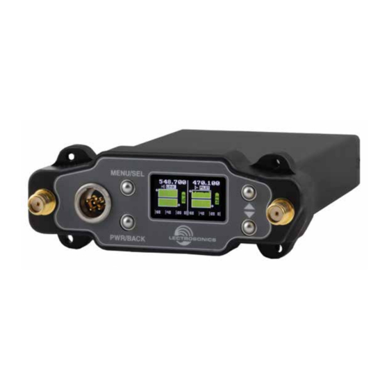
DSR
Two Channel Digital Slot Receiver
DSR-A1B1, DSR-B1C1, DSR-941, DSR-961
• Two independent channels, compact
design
• Vector diversity for superior performance
• Latest generation of SR Series:
Compatible with extensive existing
ecosystem
• Compatible with D2, HDM, Duet, DCHX
Digital modes and all Hybrid modes
Fill in for your records:
Serial Number:
Purchase Date:
INSTRUCTION MANUAL
• 24 bit/48 kHz digital for flawless audio
• AES 256-bit, CTR mode encryption, with 4
different key policies available
• Analog and AES3 digital audio outputs
• External DC powering options and USB
jack for firmware updates and data
transfer
Rio Rancho, NM, USA
www.lectrosonics.com
Advertisement
Table of Contents

Related Manuals for Lectronics DSR-A1B1


Summary of Contents for Lectronics DSR-A1B1
- Page 1 INSTRUCTION MANUAL Two Channel Digital Slot Receiver DSR-A1B1, DSR-B1C1, DSR-941, DSR-961 • Two independent channels, compact • 24 bit/48 kHz digital for flawless audio design • AES 256-bit, CTR mode encryption, with 4 • Vector diversity for superior performance different key policies available •...
- Page 2 Quick Start Summary The following checklist includes the minimum required settings to start using the receiver. • Install either a battery sled, camera slot adapter or other power source via bottom plate adapter. • Connect power to the receiver. • Set the COMPAT (compatibility) mode for the trans- mitters to be used.
-
Page 3: Table Of Contents
Two Channel Digital Receiver Table of Contents Block Diagram/Schematic ...........4 Camera Slot Adapters & Installation ......22 Technical Description ...........5 Rear Panel Adapters & Installation ......23 Front Panel Controls and Functions ......6 Adapters for Stand-Alone Use ........23 MENU/SELECT Button..........6 Battery Adapters and Mounting Kits .......24 PWR/BACK Button.............6 SRBATTSLED Top/Bottom ........24 Up/Down Arrow Buttons ..........6... -
Page 4: Block Diagram/Schematic
DSR Block Diagram LECTROSONICS, INC. -
Page 5: Technical Description
Two Channel Digital Receiver Technical Description and complete transparency is preserved. All signals presented to the transmitter’s front end, including any faint microphone hiss, will be faithfully reproduced at The DSR digital 2-channel receiver is a much-requested, the receiver. When switched to NORMAL, (the factory versatile slot receiver, equally appropriate for bag use, default setting for Hybrid modes) enough noise reduc- as well as camera hop applications. -
Page 6: Front Panel Controls And Functions
DSR Front Panel Controls After choosing the band, the unit will scan the available spectrum and choose the frequency with the lowest in- terference and will display it as shown. If there is already a frequecy programmed, you will have the choice to choose the Old (Existing Frequency) or New Frequency. -
Page 7: Tuning Groups
Two Channel Digital Receiver Digital Mode Hybrid Mode Scan Zoom: To zoom the screen, first pause the screen. Press the To manually tune: start by selecting Channel 1 or 2 in UP+DOWN buttons together to zoom (a small magnify- the upper right corner. Then, press MENU/SEL to select ing glass will appear in the right corner). -
Page 8: Diversity Modes
The DSR allows null Editing Existing Entries: testing with a special Editing group entries is done the same way they were calibration mode as created, with the exception of the “Del” (delete) box. To shown on the display. delete an entry, press MENU/SEL to navigate to the de- When the display shows lete box, then use the UP or DOWN buttons to select or “calibrate,”... -
Page 9: Audio Setup
Two Channel Digital Receiver Pilot Bypass: Smart NR: Allows the user to bypass the pilot tone on each channel Allows user to enable Smart Noise Reduction on either- while in a Hybrid compat mode and defeats the pilot tone receiver channel or both. Settings are: Off, Normal and squelch when on (no pilot tone is required). -
Page 10: Dsr Lcd Menu Map
DSR LCD Menu Map The menus presented on the LCD are arranged in a straightforward manner, with those that are likely to be used more often located at the top of the tree. Main Menu Tree Select option with arrow buttons S m a r t T u n e T x 1 R a n g e ? S e a r c h i n g . - Page 11 to toggle. P o l a r i t y P o s . N e g . Select option with arrow buttons Two Channel Digital Receiver C o m p a t M o d e to toggle. C o m p a t M o d e D C H X C h 2 H D M DSR LCD Menu Map...
-
Page 12: Ir & Keys Menu
sync. option available, and the default setting on all Lec- trosonics D2 digital units. All encryption-capable Send Frequency Lectrosonics transmitters and receivers contain Sends operating frequency to the transmitter, each chan- the Universal key. The key does not have to be nel separately. -
Page 13: Settings Menu
Two Channel Digital Receiver message “Encryption Key Sent” on the receiver display, Edit Names and “Encryption Key Received” on the transmitter display. IR key transfer failure will be indicated by the Allows the user to change the names of the Receiver message “IR Sync Failed”... -
Page 14: Antenna Mounting And Orientation
Antenna Mounting and Orientation A variety of accessories are available to enable various The diagrams below depict typical orientations of trans- mounting options. For maximum operating range, the mitter and receiver antennas in field production and how antennas should be vertical and above the camera and the RF signal transfer is affected. -
Page 15: Amj Jointed And Sna Dipole Antennas
Two Channel Digital Receiver AMJ Jointed Antenna A “bendable” mounting strap is included that allows The AMJ antenna is a general purpose design with a vertical orientation on a variety of surfaces. Several other hinged joint that pivots in both directions for positioning adapters are also available for temporary or fixed instal- the whip at any desired angle. -
Page 16: Antenna/Block Reference Table
Antenna/Block Reference Table The two AMJ whip antennas supplied with the receiver are factory cut to specific frequency blocks as shown in the table below. A colored cap and label are used on blocks 20 through 26, and a black cap and label are used on the other blocks to denote the frequency range of each model. -
Page 17: Interference Management
Two Channel Digital Receiver Interference Management Multi-channel System Checkout 3. Turn each transmitter on one at a time. Interference can result from a wide variety of sources including TV station signals, other wireless equipment in Start with all transmitters turned off. As you turn on use nearby, or from intermodulation within a multi-chan- each one, look at the matching receiver to verify a nel wireless system itself. -
Page 18: Supplied Parts And Accessories
Supplied Parts and Optional Parts and Accessories Accessories Ships With 21770 Male SMA to Female BNC Adapter. (2) AMJ19; (2) AMJ22 A1B1 (2) AMJ22; (2) AMJ25 B1C1 (2) AMJ944 21926 USB cable for firmware updates. (2) AMJ961 AMJ19 Swivelling Whip Antenna with Standard SMA Connector, Block 19. -
Page 19: Audio Output Cables/Connectors
Two Channel Digital Receiver SRSUPER UMCWBD-L Mounting adapter for SR/DSR receivers includes Unislot Rack mount with power and RF signal distribution for mounting kit, Superslot compatible. four diversity compact receivers in a single rack space. Refer to following kits for retrofit. ZS-UMC-411A-KIT Kit for UCR411A mounting. -
Page 20: Ratpac Adapter Kit
MCSRPT RATPAC Adapter Kit 12 inch long TA3 female to stripped and tinned wires for balanced output. PIN 1: Shield / PIN 2: Audio (+) white/ PIN 3: Audio (-) green. Adapter kit to build either a 3-pin or 5-pin TA Series right PIN 3: Audio (-) green angle connector. -
Page 21: External Power Cables
Two Channel Digital Receiver External Power Cables 21747 Locking LZR style plug to stripped and tinned; 6 feet long. 21746 Locking LZR style plug to stripped and tinned; 12 inches long. PS200 Hirose 7-4 pin to LZR type locking plug, 12” long. -
Page 22: Camera Slot Adapters & Installation
Camera Slot Adapters SRSUPER Adapter kit for Un- SRUNISCREWKIT islot camera slots ® such as those pro- (also for SUPERSLOT) vided on Ikegami ® Contains: Panasonic cameras, ® 3 - #28862 (longest) as well as the SL-6 5 - #28864 (mid-length) by Sound Devices ®... -
Page 23: Rear Panel Adapters & Installation
Two Channel Digital Receiver Adapters for Stand-Alone Use Rear Panel and Adapters Several different panel adapters are available to config- ure the receiver for use with popular camera slots and For stand-alone use, SREXT for stand-alone use. The adapters are retained by two this kit includes a rear screws through the side panel of the housing, making panel with two TA3... -
Page 24: Battery Adapters And Mounting Kits
Battery Adapters and Installing the SRBATTSLED Orient the battery sled so that the PCB connectors will Mounting Kits mate when the sled is inserted. Battery sled adapters configure the receiver for stand- alone use or to provide battery backup power. Several options are available: •... -
Page 25: Sr9Vbp 9V Adapter
Two Channel Digital Receiver Attach the bracket to the sleeve with the long pan head SRSLEEVE mounting adapter screw into the standard pressnut. The retaining pin fits This sleeve is supplied with Velcro swatches for mount- into the opening in the bracket. Attach the cold shoe ing an SR Series receiver on a flat surface of camera, mounting foot to the tensioning nut and rotate it to orient cart, rack, etc. -
Page 26: Troubleshooting
Troubleshooting Symptom Possible Cause INITIAL POWER ON Display not active or lit. External power supply disconnected or inadequate. Main power supply fuse tripped. Turn the receiver off, remove the cause of the overload and turn the receiver back on. Wrong polarity power source. The external DC in requires POSITIVE to be on the center pin. -
Page 27: Specifications And Features
Two Channel Digital Receiver Specifications and Features Dimensions: 3.375” wide x 1.23” high x 4.50” deep Operating Frequencies (MHz): 85.7 wide x 31 high x 114 deep mm Model A1B1: 470.100 - 614.375 Model B1C1: 537.600 - 691.175 941: 941.525 - 959.825 961: 961.100 - 1014.900 Specifications subject to change without notice. -
Page 28: Service And Repair
Service and Repair If your system malfunctions, you should attempt to correct or isolate the trouble before concluding that the equipment needs repair. Make sure you have followed the setup procedure and operating instructions. Check the interconnecting cables and then go through the Troubleshooting section in this manual. We strongly recommend that you do not try to repair the equipment yourself and do not have the local repair shop at- tempt anything other than the simplest repair. - Page 29 Two Channel Digital Receiver Rio Rancho, NM...
- Page 30 LECTROSONICS, INC.
- Page 31 Two Channel Digital Receiver Rio Rancho, NM...
- Page 32 LIMITED ONE YEAR WARRANTY The equipment is warranted for one year from date of purchase against defects in materials or workmanship provided it was purchased from an authorized dealer. This warranty does not cover equipment which has been abused or damaged by careless handling or shipping.
Need help?
Do you have a question about the DSR-A1B1 and is the answer not in the manual?
Questions and answers