Table of Contents
Advertisement
Quick Links
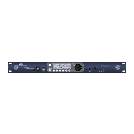
Venue 2 Modular Receiver
With Built-in Multicoupler
Two versions available:
VRM2WBL tunes bands A1, B1, B2, C1 in tuning range 470.100 to 691.175 MHz
VRM2WBM tunes bands B1, B2, C1, C2, D1, in tuning range 537.600 to 767.975 MHz
Hardware/Software Installation and Configuration
CAN RSS-Gen/CNR-Gen
Fill in for your records:
Serial Number:
Purchase Date:
Essential Setup Steps for Operation
1) Install receiver modules, connect antennas and power supply
2) Install transmitter batteries and antennas
3) Identify and set operating frequencies on the receiver using
Smart Tune
and set frequencies on the transmitters
TM
4) Attach microphones and adjust transmitter input gain
5) Verify operation with a walk test through the area where the
system will be used
INSTALLATION GUIDE
Rio Rancho, NM, USA
www.lectrosonics.com
Advertisement
Table of Contents

Related Manuals for Lectronics Venue 2


Summary of Contents for Lectronics Venue 2
- Page 1 INSTALLATION GUIDE Venue 2 Modular Receiver With Built-in Multicoupler Two versions available: VRM2WBL tunes bands A1, B1, B2, C1 in tuning range 470.100 to 691.175 MHz VRM2WBM tunes bands B1, B2, C1, C2, D1, in tuning range 537.600 to 767.975 MHz...
- Page 2 Venue 2 Wideband Receiver LECTROSONICS, INC.
-
Page 3: Table Of Contents
Digital Hybrid Wireless Modular Receiver System ® Table of Contents Introduction ................4 Firmware Update ..............17 Important Safety Instructions..........5 System Restore ..............17 Front Panel ................6 Wireless Designer Software and USB Driver ....18 Rear Panel ................7 Wireless Designer Software and USB Driver ....19 Hardware Installation ............8 Software Installer ..............19 Receiver Modules ...............8... -
Page 4: Introduction
Venue 2 Wideband Receiver Introduction Tuning Range Designation The Venue 2 Wideband receiver is a modular rack mount design for use with a wide variety of transmit- ters from Lectrosonics and other manufacturers. The VRM host assembly covers three frequency bands, and the VRT modules covers a single band (three Lec- trosonics blocks) as shown at right. -
Page 5: Important Safety Instructions
Digital Hybrid Wireless Modular Receiver System ® Important Safety Instructions 14) Refer all servicing to qualified service personnel. This symbol, wherever it appears, alerts Servicing is required when the apparatus has you to the presence of uninsulated dan- been damaged in any way, such as power-supply gerous voltage inside the enclosure -- volt- cord or plug is damaged, liquid has been spilled age that may be sufficient to constitute a... -
Page 6: Front Panel
Headphone Alert indicators buttons monitor The Venue 2 receiver mainframe (VRM2) serves as LCD Screen a “host assembly” for up to six receiver modules. The tracking receiver module (VRT2) can be mixed and The LCD is a backlit, graphics-type Liquid Crystal matched in the assembly in any combination to suit the Display used to set up and monitor system operation. -
Page 7: Rear Panel
Windows® Vista , Windows 7/8/10 or Mac OSX A serial RS-232 interface is provided for setup and operating systems. control of a Venue 2 system from computers or other devices using industry standard RS-232 communication links. Rio Rancho, NM, USA... -
Page 8: Hardware Installation
Venue 2 Wideband Receiver Hardware Installation Removing Receiver Modules Receiver Modules 1. Turn the power off. All modules must be within the frequency passband of the host assembly. Frequency bands are marked on 2. Gently pull outwards on the side panel and push the receiver modules. -
Page 9: Audio Outputs
Digital Hybrid Wireless Modular Receiver System ® Audio Outputs Balanced XLR audio outputs on the rear panel can be used to drive balanced or unbalanced inputs at line level on any type of mixer, recorder or other type of audio equipment. Note: When the modules are paired for diversity operation, the audio will appear at both XLR jacks associated with the module pair. -
Page 10: Lcd Interface
Venue 2 Wideband Receiver LCD Interface Navigating the Menus When the receiver is turned on, LCD will show the Three menus are provided for complete system setup: model number, firmware version and serial number • Top Menu for overall system settings during the boot sequence. -
Page 11: Using Setup Screens
Digital Hybrid Wireless Modular Receiver System ® Using Setup Screens The FREQ ADJUST setup screen in the RX Menu shown here is another type of a multiple module setup screen. The difference from the previous example is When a menu item is selected, a setup screen will that this type presents multiple settings within each open to enable adjustments and settings to be made. -
Page 12: Setup Details
Venue 2 Wideband Receiver Setup Details Audio Output Levels Setup The output level of the installed receiver modules can Direct Access to Receiver Setup be adjusted in a single setup screen in the RX Menu. Basic adjustments to each receiver can be made in a single screen available with the numbered Receiver Select button below the frame of each receiver. -
Page 13: Diversity Pairing
Digital Hybrid Wireless Modular Receiver System ® Optimizing the Signal to Noise Ratio Modulation (audio level) Given the information above, the optimum signal to noise ratio is achieved when the least amount of gain is applied to the signal, since gain (amplification) is the source of noise buildup. -
Page 14: Talkback Setup
A simple setup screen in the Venue 2 receiver makes it easy to des- ignate channels with this function enabled and which output will deliver the talkback audio. -
Page 15: Top Menu System Info
Digital Hybrid Wireless Modular Receiver System ® IR Transmitter Setup Top Menu SYSTEM INFO Firmware and hardware versions and the serial num- The IR (infrared) port simplifies transmitter setup by ber of the unit is listed in the SYSTEM INFO screen. sending the settings saved in the receiver to an IR en- abled transmitter. -
Page 16: Smart Tune Tm
Venue 2 Wideband Receiver Smart Tune After selecting the receiver to use for the scan, select START and press the encoder. The START item will change to STOP while the scanning is taking place. Clear frequencies can be discovered automatically us- ing the SmartTune utility. -
Page 17: Firmware Update
Digital Hybrid Wireless Modular Receiver System ® Firmware Update Firmware updates are detailed in the Wireless De- 4) The unit will now be in the “Recovery Mode.” Re- signer software help file. Launch the software and click lease the Recovery Mode button. on Online Help, then on Venue2 Receiver Setup and 5) Open Wireless Designer, and proceed to update Monitoring, then on the item for updating firmware. -
Page 18: Wireless Designer Software And Usb Driver
WD 64-bit USB Driver... is for use with the DR digital receiver or Venue 2 receiver http://www.lectrosonics.com/europe/ LecNet2 64-bit USB Driver... is for use with earlier or use the flash drive supplied with the receiver. -
Page 19: Wireless Designer Software And Usb Driver
Digital Hybrid Wireless Modular Receiver System ® Wireless Designer Software Installer Installation oftware supplied on USB drive. Can also be Software and USB Driver downloaded from the web site. Software for Mac OS X Operating Systems ® Installation Using only the Firefox web browser, open Wireless Designer. -
Page 20: Top Menu
Venue 2 Wideband Receiver Menu Map TOP MENU TOP MENU DETECT takes an inventory of the receiver modules installed in the mainframe and displays the results in an on-screen table. DETECT SMART TUNE SMART TUNE is an automatic process that scans the tuning range of all modules and automatically finds clear frequencies. - Page 21 Digital Hybrid Wireless Modular Receiver System ® SPECTRUM BACK LIGHT ANTENNA NETWORK RS232 SETUP COMMAND SYSTEM INFO LOCK PANEL SCAN POWER SETUP VIEW TX AUDIO LF ROLLOFF TX PHASE PROG SWITCH AUTO ON TX PANEL BATT TIMER TX BACKLIGHT STEP SIZE NARROW BAND GAIN LOCK...
-
Page 22: Rx Menu
Venue 2 Wideband Receiver RX MENU COMPAT MODE sets the DSP-based compatibility mode for each channel. TOP MENU links back to the Top Menu for overall system setup. TALKBACK enables the Talkback Mode on the desired channels and selects the FREQ ADJUST opens a setup screen to output channel for the talkback audio. -
Page 23: Connecting To A Network
USB port. Launch Wireless Designer. Turn on • Client devices the Venue 2 receiver, or turn it off and back on if it’s already turned on. Wait for the receiver to fully boot An example of a simple network is a modem used in a up (the main window appears). -
Page 24: Multi-Channel System Checkout
Scanning with the RF spectrum analyzer built into the Venue 2 system will identify external RF signals, but it does not address the compatibility of the selected frequencies. -
Page 25: Antennas
Antennas Use and Placement Using Remote Antennas The Venue 2 mainframe is designed for rack mounting. Remote antennas can be placed at a distance from Although it can be operated with two whip antennas, it the receiver to optimize reception. To overcome loss... -
Page 26: Front Mounted Antennas
Venue 2 Wideband Receiver Front Mounted Antennas Step 3 Remove the four screws holding the chassis cover, The internal coaxial cables and connectors can be then remove the cover by lifting the rear up. moved to the front panel if so desired, using small flat blade and Phillips screwdrivers. - Page 27 Digital Hybrid Wireless Modular Receiver System ® Step 5 Step 9 Align the flats on the BNC connectors with the flats in The coaxial cables should route toward the front of the the holes in the front panel and secure them with the receiver as shown so the cable fits loosely under the lock washers and nuts.
-
Page 28: Accessories And Common Replacement Parts
Venue 2 Wideband Receiver Accessories and Common Replacement Parts Remote Antennas ALP500 ALP Series LPDA (log periodic dipole array) models ALP620 SNA600A folding dipole antenna ALP650 ALP Kit mounting hardware Coaxial Cable ARG2 coaxial cable - 2 ft. length ARG15 coaxial cable - 15 ft. length ARG25 coaxial cable - 25 ft. -
Page 29: Service And Repair
Digital Hybrid Wireless Modular Receiver System ® Service and Repair If your system malfunctions, you should attempt to correct or isolate the trouble before concluding that the equip- ment needs repair. Make sure you have followed the setup procedure and operating instructions. Check the inter- connecting cables and then go through the TROUBLESHOOTING section in this manual. - Page 30 Venue 2 Wideband Receiver LECTROSONICS, INC.
- Page 31 Digital Hybrid Wireless Modular Receiver System ® Rio Rancho, NM, USA...
- Page 32 LIMITED ONE YEAR WARRANTY The equipment is warranted for one year from date of purchase against defects in materials or workmanship provided it was purchased from an authorized dealer. This warranty does not cover equipment which has been abused or damaged by careless handling or shipping.
Need help?
Do you have a question about the Venue 2 and is the answer not in the manual?
Questions and answers