Advertisement
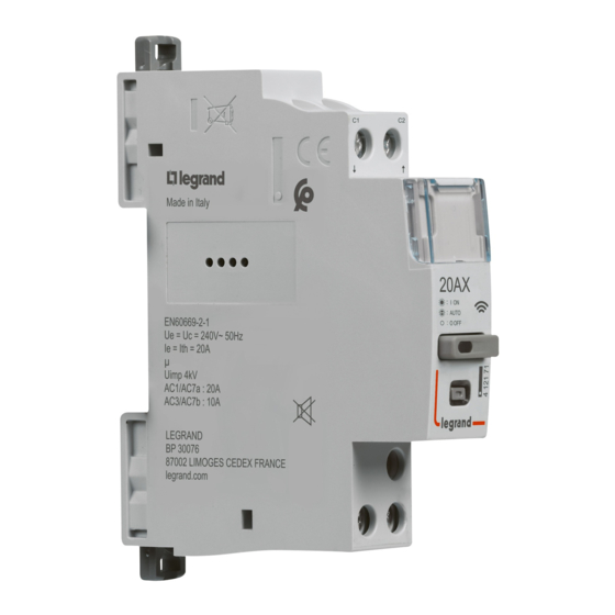
Connected Contactor
4 121 71 - 1 991 22
Requires the installation of a:
Gateway module
Composition
Connected Contactor
F
2,4 à
Silent
2,4835Ghz
< 10dB
<100 mW
U
-5°C
100-240V~
+45°C
50/60Hz
OR
EN 60669-2-1
ON/OFF
AUTO
1
1
oooooooooooooooo
2
2
oooooooooooooooo
3
4
3
ooooooooooo
5
4
oooooooooooooo
6
5
ooooooooooo
7
6
ooooooooooooooo
8
7
oooooooo
10
9
8
11
ooooooooooooo
12
9
oooooo
13
10
oooooooooooooo
14
11
ooooooooooo
15
12
oooooooooooooooo
17
16
13
oooooooooooooo
18
19
14
ooooooooooo
20
15
oooooooooooooo
21
16
oooooooooooo
22
17
ooooooooooooooo
23
24
18
oooooooooooooo
25
19
26
ooooooooooo
27
20
oooooooooooooooo
28
kWh
21
oooooooooooooo
29
22
ooooooooooo
30
23
oooooooooooooo
24
oooooooooooooooo
25
ooooooooooo
26
oooooooooooooooo
Mar
27
oooooooooooooo
28
ooooooooooo
29
oooooooooooooo
30
oooooooooooo
Planning Measure
Shedding
I
kWh
Connected
20A MAX
shedding
compatible
Connected Starter Pack
"... with Netatmo"
Control wiring
authorized
L
Self-protected
MCB
C1
C2
C1
EV plug
4800W
2400VA
remote
Imperative security precaution
The instructions for installation and
use must be strictly observed in order
to avoid the risk of electric shock or fire.
Any kind of
OR
"with Netatmo"
gateway
C1
line OUT
C2
N
LED
FLUO
3840W
650W
C2
Load
L
3000W
Advertisement
Table of Contents

Related Manuals for LEGRAND 4 121 71


Summary of Contents for LEGRAND 4 121 71
- Page 1 Connected Contactor 4 121 71 - 1 991 22 Requires the installation of a: Gateway module Connected Starter Pack "... with Netatmo" Any kind of “with Netatmo” gateway Composition Control wiring authorized EN 60669-2-1 Self-protected line OUT ON/OFF AUTO Load...
- Page 2 C1, C2: Preparation, connection 2x 1.5mm² 2.5mm² N, L, Load: 2x 2.5mm² Turn off the power 6mm² at general C1,C2, circuit breaker N, L, Load: MIN : 0.8Nm 4 mm MAX : 1.4Nm Wiring examples Thanks to its control circuit with integrated power and protection, you no longer need to install a circuit breaker 2A to protect the control circuit if you wire a contact between C1 and C2.
- Page 3 **: After wiring the installation, refit the front plate so that no active live part is accessible. Finalize the installation in the Legrand Home + Control app Download the Home + Control App and follow the instructions for adding the connected product in your setup.
- Page 4 (> 5 seconds) until the configuration indicator lights up in fixed red. It is no longer associated with the gateway present in the installation. >5s www.legrand.fr/reference/412171 LEGRAND - Pro and Consumer Service - BP 30076 87002 LIMOGES CEDEX FRANCE • www.legrand.com SIMPLIFIED DECLARATION OF CONFORMITY The undersigned, Legrand declares that the radio equipment listed on this instruction sheet are compliant to the directive 2014/53/UE.
Need help?
Do you have a question about the 4 121 71 and is the answer not in the manual?
Questions and answers