Table of Contents
Advertisement
No: 24811 – 12/16 rev. 1
Catalog Numbers • Les Numéros de Catalogue • Números de Catálogo: LMCP8/LMCP24/LMCP48
Country of Origin: Made in China • Pays d'origine: Fabriqué en Chine • País de origen: Hecho en China
Wattstopper
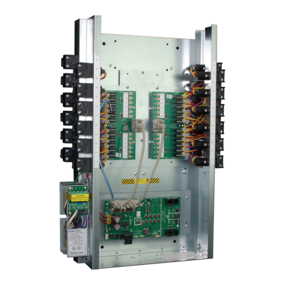
Relay Panel Interiors
Panel with Digital Lighting Management Support
User Manual
SPECIFICATIONS
Input voltage ....................... 115/277V 60 Hz, 120/347V 60 Hz, 240V 60 Hz
Class 2 connection to two independent DLM local networks 24VDC
output, up to 250mA across 2 RJ45 ports per local network (A and B
networks, 250 mA each).
Free-topology DLM local network segments may include Digital Lighting
Management (DLM) switches, occupancy sensors, daylight sensors and
input modules
Category 5e cable, up to 1,000 ft. total per local network
Terminals for connection to DLM segment network (BACnet MS/TP)
Segment network parameters
WattStopper LM-MSTP wire
Linear topology; 4000 ft. maximum per segment
Accessory power (jumper selectable)
LMCP8 ........................................................................................N/A
LMCP24 ...............................650 mA @ 15VDC, 400 mA @ 24VDC
LMCP48 ...............................650 mA @ 15VDC, 400 mA @ 24VDC
.................................................15VDC to power Segment Manager
............................................. 24VDC for Class 2 accessory devices
HDR relays:
Coil voltage, 24 VDC, pulse ON and pulse OFF
Mechanically latched contacts
½" K.O. mounting, LV plug-connection, individually replaceable
Contact ratings:
@ 277V .......................................................................... 30 A ballast
@ 347V .......................................................................... 20 A ballast
@ 120V .......................................................................20 A tungsten
@ 347V ....................................................................... 30 A resistive
@ 120V ..................................................................................1.5 HP
SCCR (short circuit current rating) 14,000 A @ 347VAC with HDR
Heavy Duty Relay
Operating conditions:
for indoor use only ......................................... 32-140 oF (0 – 60 oC)
............................................................. 5-95% RH, non-condensing
UL and CUL listed
WARNING: The DB9 cables cannot be plugged in or unplugged without
powering down the panel.
®
Advertisement
Table of Contents


Need help?
Do you have a question about the Wattstopper LMCP8 and is the answer not in the manual?
Questions and answers