Table of Contents
Advertisement
Quick Links
Advertisement
Table of Contents

Related Manuals for Huvitz CLM-7000


Summary of Contents for Huvitz CLM-7000
- Page 1 User’s Manual Automatic Lensmeter CLM-7000 Ver 1.0...
- Page 2 SHANGHAI HUVITZ reserves the right to make changes in its products or product specifications at any time and without prior notice, and is not required to update this documentation to reflect such changes.
-
Page 3: Table Of Contents
CLM-7000 User Guide -------------------------------------------------------------------------- CONTENTS INTRODUCTION ......................4 1.1..................4 UTLINE OF THE INSTRUMENT 1.2......................4 LASSIFICATION SAFETY INFORMATION .................... 5 2.1......................5 NTRODUCTION 2.2....................... 6 AFETY YMBOLS 2.3..................... 7 NVIRONMENT FACTORS 2.4....................9... - Page 4 ------------------------------------------------------------------------- CLM-7000 User Guide 8.3. UV S ......................25 CREEN 8.4. )..............26 ONTACT ISPLAY 8.5.................. 27 UNGLASSES ISPLAY 8.6......................27 ETUP CREEN 8.7....................32 RINTOUT ORMAT MEASUREMENTS ..................... 33 9.1......................33 ORMAL LENSES 9.2......................35 RAMED LENSES 9.3.
-
Page 5: Introduction
Introduction 1.1. Outline of the instrument The Automatic Lensmeter CLM-7000 is the equipment for measuring the refractive power of lenses and gives the spherical, cylindrical and axis of the lenses. The Automatic Lensmeter C LM-7000 also contains the PD(=pupil distance) measurement and the UV Protection Ratio Test. -
Page 6: Safety Information
------------------------------------------------------------------------- CLM-7000 User Guide Safety Information 2.1. Introduction Safety is everyone’s responsibility. The safe use of this equipment is largely dependent upon the installer, user, operator, and maintainer. It is imperative that personnel study and become familiar with this entire manual before attempting to install, use, clean, service or adjust this equipment and any associated accessories. -
Page 7: Safety Symbols
Protective earth connected to conductive parts of Class I equipment for safety purposes. Extra Symbols External serial communication port. User can transmit the memorized data to other equipment such as Shanghai Huvitz’s other machines or PC. -
Page 8: Environment Factors
------------------------------------------------------------------------- CLM-7000 User Guide 2.3. Environment factors Avoid the following environments for operation or storage Where the equipment is exposed to water vapor. Don’t operate equipment with a wet hand. Where the equipment is exposed to direct sunlight . Where the temperature changes extremely. - Page 9 CLM-7000 User Guide -------------------------------------------------------------------------- Be careful not to be inserted dust, especially, metal. Don’t disassemble the product or open. We aren’t responsible for it for nothing. Be careful not to close the fan located on the l ateral or rear side of the equipment.
-
Page 10: Safety Precautions
The equipment must be operated only by, or under direct supervision a properly trained and qualified person. Modifications of this equipment may only be carried out by Shanghai Huvitz’s service technicians or other authorized persons. Customer maintenance of this equipment may only be performed as stated in the User’s Manual and Service Manual. - Page 11 CLM-7000 User Guide -------------------------------------------------------------------------- This equipment may only be used together with accessories supplied by Shanghai Huvitz’s. If the customer makes use of other accessories, use them only if their safe usability under technical safety aspects has been proved and confirmed by Shanghai Huvitz or the manufacturer of the accessory.
-
Page 12: Features
6. Measuring progressive multi-focal lenses and general multi-focal lenses can be performed easily and rapidly. 7. CLM-7000 can measure soft contact lenses easily and accurately using the specialized mechanical jig and the display. (but, contact lens zig is optional) 8. CLM-7000 supports gorgeous displays through the proper colored LCD. -
Page 13: Notes For Using The Instrument
CLM-7000 User Guide -------------------------------------------------------------------------- Notes for using the instrument Do not hit or drop the instrument. The instrument may be damaged if it receives a strong impact. The impact can damage the function of this instrument. So handle with care. -
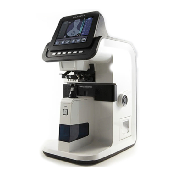
Page 14: Configurations
------------------------------------------------------------------------- CLM-7000 User Guide Configurations 5.1. Main Unit 1. LCD 2. Key Button 7. Marking Lever 3. Lens Holder 8. Lens Table 4. Lens Support 9. Table Lever 5. Menory Button 10. Printer 6. UV Cover [Figure 1. Component Names (I)] 1. - Page 15 CLM-7000 User Guide -------------------------------------------------------------------------- 1. Power Switch [Figure 2. Component Names (II)] 2. Power Connector [Figure 3. Component Names (III)] 1. Power Switch 2. Power Connector...
-
Page 16: Accessories
------------------------------------------------------------------------- CLM-7000 User Guide 5.2. Accessories Printing Paper Dust Cloth Fuse (250V, T3.15AL) Tweezers : A kind of tool to pick up the contact lens Power Cable Dust Cap User’s Manual Blower 10) Ink Case 11) Contact Lens Jig : mechanical jig for measuring a contact lens (Optional) -
Page 17: Settings And Preparation For Operating
CLM-7000 User Guide -------------------------------------------------------------------------- Settings and Preparation for Operating 6.1. Receiving inspection Step 1. Checking accessories. 12) Open the box and make sure that all the accessories (printing paper, Dust Cloth, user’s manual and so on) are in it Step 2. Removing the protection tape. -
Page 18: Display Protection Function
------------------------------------------------------------------------- CLM-7000 User Guide Turn on the machine. Make sure that there is nothing on the lens cap. If you encounter the message “No Signal” or “Out of range”, please clean the 4- pin hole. And then turn on again. -
Page 19: Buttons For Operations
CLM-7000 User Guide -------------------------------------------------------------------------- Buttons For Operations 7.1. Switching Screen According To the Button Selection Normal Lens Mode Progressive Lens Mode Soft Contact Lens Mode Hard Contact Lens Mode UV Lens Mode D-Sunglasses Lens Mode [Figure 5. Switching Screen According To the Button Selection]... -
Page 20: Usage Of Buttons
------------------------------------------------------------------------- CLM-7000 User Guide 7.2. Usage of buttons MODE Setup Screen will be shown TRNS To transpose the sign of cylindrical reading PROG Enter the Progressive Multi-Focal Screen SOFT CNCT To go into the display for soft contact lens HARD CNCT... - Page 21 CLM-7000 User Guide -------------------------------------------------------------------------- LENS To return to the display for the normal lens S→R In case of single lens, you can switch between left and right selection of the framed lens or you can select left /right lens CLEAR To Initialize data and convert screen.
-
Page 22: Description Of Screen Layout
------------------------------------------------------------------------- CLM-7000 User Guide Description of Screen Layout 8.1. Measurement Screen 1. Active Direction 4. Measuring point 5. Lens Type 2. Cylinder 3. Sequential No. 6. Measured Data 7. Message Box 11. Total PD 10. ABBE Data 8. State icon 9. - Page 23 CLM-7000 User Guide -------------------------------------------------------------------------- 8.1.1. Detail explanation ① Active Direction Tells whether current lens is a single or a left/right lens. ② Cylinder Displays the cylinder value with (+) sign when the power has (+) value and with (-) sign when the power has (-) value ③...
- Page 24 ------------------------------------------------------------------------- CLM-7000 User Guide ALIGNMENT OK : is displayed when the optical center falls within 0.5 prism. MARKING OK : is displayed when the optical center is precise. And it tells that you can mark focus and cylindrical axis after you adjust the angle using the marking lever.
-
Page 25: About The Progressive Display
CLM-7000 User Guide -------------------------------------------------------------------------- 8.2. About the progressive display 1. Maximum ADD 2. Horizontal Guide Line 3. Measuring Point 4. Target for Far Vision 5. Addition [Figure 7. The display for the progressive powered lens] 8.2.1. Detail explanation ① Maximum ADD The maximum additive value after detecting the far vision focus. -
Page 26: Uv Screen
------------------------------------------------------------------------- CLM-7000 User Guide 8.3. UV Screen 2. Current Transmission Ratio 3. Right 1. Left Transmission Ratio Transmission Ratio 4. Transmission Height [Figure 8. UV Screen Layout] 8.3.1. Detail explanation ① Left Transmission Ratio Shows the left-side stored value. ②... -
Page 27: Contact Lens Display (Soft, Hard)
CLM-7000 User Guide -------------------------------------------------------------------------- 8.4. Contact Lens Display (Soft, Hard) 1. Signal 2. Start/Stop Record 3. Score Graph Of Each Point [Figure 9. Contact Lens Display] 8.4.1. Detail explanation ① Signal Shows the share of every signal. ② Start/Stop Record Start : Start recording the continuous measurement. -
Page 28: D-Sunglasses Lens Display
------------------------------------------------------------------------- CLM-7000 User Guide 8.5. D-Sunglasses Lens Display [Figure 10. D-Sunglasses Lens Display] 8.6. Setup Screen [Figure 11. Setup Display]... - Page 29 CLM-7000 User Guide -------------------------------------------------------------------------- 8.6.1. Detail explanation LENS - NORMAL : normal lens - PROGRESSIVE : progressive lens - SOFT CONTACT : soft contact lens - HARD CONTACT : hard contact lens - UV : uv lens - SUNGLASSES : dark sunglasses lens...
- Page 30 ------------------------------------------------------------------------- CLM-7000 User Guide PRISM - NO DISPLAY : will not display the prism information. - X Y : displays the prism information in X-Y coordinates. - P B : represents the prism information with absolute distance and angle. - mm : displays the center difference in (x, y) coordinate by millimeter (mm).
- Page 31 CLM-7000 User Guide -------------------------------------------------------------------------- WAVELENGTH - e Line : displays the refractive power according to e-Line - d Line : displays the refractive power according to d-Line SLEEP MODE - ON : turns on the display protection mode. - OFF : turns off the display protection mode.
- Page 32 ------------------------------------------------------------------------- CLM-7000 User Guide - ON(DEFAULT) : turns on the PD function - OFF : turns off the PD function - ON(AVERAGE ST): turns on the special PD function that makes the RPD and LPD even in case that the difference between RPD and LPD is less than 3mm.
-
Page 33: Printout Format
CLM-7000 User Guide -------------------------------------------------------------------------- INFORMATION Using ‘AUTO MEASURE’, ‘AUTO PRINTER’, ‘RS 232C’, ‘PRINTER’, you can achieve the full automatic measurement. TIME To configure date and time. INFORMATION Select the input position by the left fourth and the fifth button and increase/decrease the number by the second and the third button. -
Page 34: Measurements
------------------------------------------------------------------------- CLM-7000 User Guide Measurements 9.1. Normal lenses [Figure 13. How To Measure a Normal Lens] Step 1 Press ‘CLEAR’ button( ) to initialize the state of measurement. The symbol ‘S’ must appear on the upper-right part of the screen. (But, ‘ AUTO R/L ’... - Page 35 CLM-7000 User Guide -------------------------------------------------------------------------- Step 4 If the lens has astigmatism power, turn the lens so that the astigmatism an gle become 180°. INFORMATION You don’t have to control astigmatism power to 180°if there is no astigmatism power or you have no plan to mark astigmatism focus and cylindrical axis.
-
Page 36: Framed Lenses
------------------------------------------------------------------------- CLM-7000 User Guide INFORMATION In case of a lens with power, the figure on the left bottom of the screen will display lens support with lens. CAUTION Move lens gently and softly with care. After placing the lens on the lens support, Lower-directed impact or sudden moving might result in the scratch or crack of the lens. - Page 37 CLM-7000 User Guide -------------------------------------------------------------------------- Step 2 Place the right lens on the support and lower the lens holder. Step 3 Place the PD location sensor in the middle of the frame when PD function is on. Step 4 Press the ‘MEM’ button to store the measured data.
-
Page 38: Progressive Multi-Focal Lenses
------------------------------------------------------------------------- CLM-7000 User Guide 9.3. Progressive Multi-Focal Lenses 9.3.1. The structure of progressive powered lens The Uncut Lens Lens Table Eye point mark for near Eye point mark for distance(=far) [Figure 17. The structure of single lens] INFORMATION The lens should be placed with its horizontal marks parallel to the lens table. - Page 39 CLM-7000 User Guide -------------------------------------------------------------------------- INFORMATION The dimension of progressive powered lens depends on the specification of manufacture. INFORMATION The old type progressive lens may not observe the 2~3mm shift toward the frame center. INFORMATION Do not lift up the lens by hand at the time of measurement. Place the lens holder over the lens in order to hold the lens by foot.
- Page 40 ------------------------------------------------------------------------- CLM-7000 User Guide Step 3 The icon in the left bottom of display will be changed as below (Standard → Progressive icon). The display will be automatically changed to progressive mode. [Figure 20. The changes of state icon] INFORMATION Automatic Detection may not be available in case the progressive power is less than 1D.
- Page 41 CLM-7000 User Guide -------------------------------------------------------------------------- INFORMATION Automatic detection may not be available if the progress area is expanded into the far vision focus. In this case placed the cross marker (+) at the close point to the center and press “ MEM ” button to set the focus of far vision.
- Page 42 ------------------------------------------------------------------------- CLM-7000 User Guide INFORMATION In case the horizontal indicator is out of the tolerance range, move the right lens to right (left lens to left), since the near focus is located at 2~3mm toward the center of frame. Step 2 Pull the lens till the vertical indicator for near focus reaches to the criteria for near focus.
- Page 43 CLM-7000 User Guide -------------------------------------------------------------------------- 9.3.5. roubleshooting for progressive measurement ① Do not detect the progressive lens automatically Cause 1 : Lens holder is not located in the progressive area (Normal lens icon will be displayed in the left bottom of display.) Solution : Move the lens to the progressive area for progressive measurement.
-
Page 44: General Multi-Focal Lenses
------------------------------------------------------------------------- CLM-7000 User Guide Cause 1 : Lift up the lens by hand at the time of measurement Solution : Place the lens holder over the lens in order to hold the lens by foot. Then move the lens forward/backward or left/right for measurement. -
Page 45: Soft Contact Lenses (Contact Lens Zig Is Optional)
CLM-7000 User Guide -------------------------------------------------------------------------- 9.4.2. Measuring at the Progressive Display Step 1 Press the ‘ PROG ’ button( ) to activate the progressive display. Step 2 Place the lens over the first focus. The measurement is done automatically. Step 3 Move the lens over the second focus. And then the measurement is done automatically. -
Page 46: Hard Contact Lenses
------------------------------------------------------------------------- CLM-7000 User Guide INFORMATION You can specify the measurement duration at the User Setup Page. And then if you turn on the ‘AUTO REC’ function, it is unnecessary for you to press ‘STOP RECORD’ button( ) to stop the continuous measurement. -
Page 47: D-Sunglasses Lenses
CLM-7000 User Guide -------------------------------------------------------------------------- Step 3 Press the ‘CAL’ button( ) to calibrate the transmission ratio into 100% if it is not. Step 4 Place the lens on the UV detector. Step 5 Press the ‘MEM’ button to memorize the transmission ratio and press the ‘PRINT’... -
Page 48: Prism
------------------------------------------------------------------------- CLM-7000 User Guide [Figure 23. How To Mark Focus and Cylindrical Axis] 9.9.2. When there is astigmatism Step 1 Place the lens and control the lens so that it becomes ‘MARKING OK’. Step 2 Keep ‘MARKING OK’ and control lens up to the angle of prescription slip. -
Page 49: Maintenance
CLM-7000 User Guide -------------------------------------------------------------------------- 10. Maintenance 10.1. Replacing Printing Paper [Figure 24. How to Replace the Printing Paper] Step 1 Open the printer cover. Step 2 Insert the paper into the printer shaft and put the shaft into the pre- defined position. -
Page 50: Replacing Fuse
[Figure 25. Replacing fuse] Step 1 Pull out the fuse box. Step 2 Replace the old one with the new one. Step 3 Put into the fuse box with the new one. INFORMATION Use 250V, T3.15AL fuse for the Auto Lensmeter CLM-7000. -
Page 51: Storage
CLM-7000 User Guide -------------------------------------------------------------------------- 10.3. Storage During night time, be sure to cover the dust cloth as the below picture, because some dust might make spoil your equipment. [Figure 26. Storage for night time] If you don’t use your equipment for one week or more, make sure that the dust cap should be fitted into the lens support as the below picture. -
Page 52: Disposal
------------------------------------------------------------------------- CLM-7000 User Guide 10.4. Disposal NOTE To dispose the instrument, accessories, and components, follow local governing ordinances and recycling plans regarding disposal or recycling of instrument or device components. Especially a lithium battery may pollute the environment if the instrument or a lithium battery is abandoned. -
Page 53: Troubleshooting
CLM-7000 User Guide -------------------------------------------------------------------------- 11. Troubleshooting 11.1. Various Messages Message box shows information when you are measuring or this instrument is out of order. Here is the description on messages that appear in measuring. ALIGNMENT OK : When the optic center falls within 0.5 prism. - Page 54 Never use liquids such as alcohol, acetone, etc. Because such liquids might melt the glue on the 4-pin hole. After that, if the message “No Signal” or “Out of range” isn’t be disappeared, please ask to your local distributor or the Shanghai Huvitz service department.
-
Page 55: Specifications
CLM-7000 User Guide -------------------------------------------------------------------------- 12. Specifications Measurement Range Sphere Power -25D ~ +25D Cylinder Power 0 to ±10.00D Cylinder Axis ~ 180 degrees(1 Step) Add Power 0 to +10D Prism Power 0 to 10 Precision Diopter Steps 0.01 / 0.125 / 0.25D Prism Power 0.01 / 0.125 / 0.25... -
Page 56: Service Information
Model No. : Serial No. : If you can’t contact with your local distributor, you can directly get in touch with the service department of the SHANGHAI HUVITZ using the phone number and the address written in the below table.
Need help?
Do you have a question about the CLM-7000 and is the answer not in the manual?
Questions and answers