Table of Contents
Advertisement
Quick Links
Advertisement
Table of Contents

Related Manuals for Huvitz HLM-1


Summary of Contents for Huvitz HLM-1
- Page 2 Auto Lensmeter HLM-1 Service Manual Auto Lensmeter HLM-1...
-
Page 3: Table Of Contents
INDEX INTRODUCTION ......................... 4 1.1............................. 4 OMPONENTS 1.2............................. 6 EPAIR ROCEDURE 1.3................................7 AUTIONS 1.4............................7 OFTWARE VERSION 1.5..............................7 PTICAL YSTEM 1.6..........................8 EASUREMENT RINCIPLE CHECKING AND SETUP METHOD ..................9 2.1............................... 9 ETUP RDER 2.2. - Page 4 Auto Lensmeter HLM-1 ELECTRICAL BLOCK DIAGRAM....................42 4.1.......................... 42 LECTRICAL BLOCK DIAGRAM 4.2. SMPS............................44 NSPECTING 4.3. LCD TEST ................................ 45 4.4. LED TEST................................. 45 HOW TO UPGRADE THE FIRMWARE SOFTEWARE ............42 5.1............................... 426 NTRODUCTION 5.2..447...
-
Page 5: Introduction
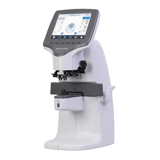
Introduction Components List 1.1. LCD Screen Button Marking Lever Lens Table Lens Table Lever Lens Holder Lever Lens Cap MEM Button (Save Button) Figure 1. Components Names (I) - Page 6 Auto Lensmeter HLM-1 Power Switch Figure 2. Components Names (II) RS-232 Connector Power Connector Figure 3. Components Names (III)
-
Page 7: Repair Procedure
Repair Procedure 1.2. Power ON 1. Examining the Internal Components First 2. Inspecting The value, S.C.A. Prism Normal State Checking Abnormal State Cleaning the Pinhole Power off and on Normal State Checking Abnormal State Setup Again Exit Figure 4. Repair procedure flow chart... -
Page 8: Cautions
Auto Lensmeter HLM-1 Cautions 1.3. Always protect this instrument with Dust Cover after using. Do not vibrate or drop this instrument; it can cause damage. Use soft cloth or cotton swaps with alcohol when clean the pinhole. -
Page 9: Measurement Principle
Signal Receiving Part Hartmann plate : divide the signal into 81 points. Prevent the other light except the signal 2-dimentional CMOS sensor : converts signals into digital value. Measurement Principle 1.6. Basic Principle When there is no lens (0D state), parallel light that has transmitted the collimator lens passes the pinhole and makes image on CCD. -
Page 10: Checking And Setup Method
Auto Lensmeter HLM-1 2. Checking and Setup Method Setup Order 2.1. Start up with pressing 3 and 6 keys, then you can meet “Setup Mode” as below. While this mode, ‘SETUP MODE’ mark will show in the upper area. Calibration can be processed only in SETUP mode; LENS, PRISM, CYLINDER. To all setting, you should convert the display step (STEP) into 0.01. -
Page 11: How To Set Origin
How to Set Origin 2.2. The steps of setting origin are as follows: Press the ‘LENS’ (Key 1) button. Press the ‘MEASURE’ (Key 2) button. C. Determine the lens to measure by using two ‘-INDEX’, ’+INDEX’ buttons. D. ‘D-0.01’ button and ‘D+0.01’ button by the given value in the Standard Lens-set specification. -
Page 12: How To Set 12 Standard Lenses
Auto Lensmeter HLM-1 If you want to return to the previous one without saving in the SAVE screen, press the rightmost ‘PREV’ button. How to Set 12 standard lenses 2.3. If the measured value is not accurate, you should set the diopter variables again by using the standard lens-set: for all the 12 lenses in the standard lens set. -
Page 13: How To Set Prism
How to Set Prism 2.4. If the measured value is not accurate, you should set the 2, 5, 10, 15, 20 lens again by using the standard lens-set. First, convert prism display format into P-B. Then, press the ‘PRISM’ (Key 2) button. C. -
Page 14: The Calibration Of The Cylindrical Axis
Auto Lensmeter HLM-1 ANGLE PRISM BASE 0° ~ 30° center 31° ~ 60° center 61° ~ 90° center 91° ~ 120° center 121° ~ 150° center 151° ~ 180° center 181° ~ 210° center 211° ~ 240° center 241° ~ 270° center 271°... - Page 15 C. ‘-0.01’ button and ‘+0.01’ button by the given value in the Standard Lens-set specification. D. Locate it to the center while cling it to the lens. (Axis : 90°, Prism_x, y: 0) E. Press the ‘MEASURE’ button and check if ‘A90’ value is changed. F.
-
Page 16: Diopter Setting Variables List
Auto Lensmeter HLM-1 Diopter Setting Variables List 2.6. The followings are diopter setting variables list: WAVEFRONT DATA INFORMATION [ALL DIOPTER] 0 [-25.01]: L=+174.05; 123.48, 122.67: average distance and distance rates between the four points and -25D 1 [-19.99]: L=+168.52; 119.09, 119.23: average distance and distance rates between the four points and -20D …... -
Page 17: How To Change The Ccd Camera
How to change the CCD camera 2.7. The procedures for changing a camera are as followings. A. Remove all subassemblies that are the side cover, the lens table and the lower cover and the CCD cover etc. B. Loose the Base Screw I and then take out the old CCD assembly. C. - Page 18 Auto Lensmeter HLM-1 We should place the CMOS Camera keeping two conditions: The first condition is the position of center point. The center position is shown at the 5 row like this. - CEN: (+640.00, +512.00) It must be within ( +640.00 ± 15, 512 ± 15 ) The second one is the orientation of CMOS Camera.
-
Page 19: How To Change The Led Assembly
How to change the LED Assembly 2.8. The spare part for the LED assembly is the Upper Frame. So, we provide all upper frame assembly for the LED assembly. The procedures for changing the upper frame Assembly are as followings: A. - Page 20 Auto Lensmeter HLM-1 3. Loose and take out the screws in Upper Holes. 4. Loose the Socket Set Screws. 5. Lift up the Pinhole Housing and replace it the new one. 6. Turn on the machine to the Setup Mode and then press ‘LENS’ (Key 1) button for a while to go into the Calibration Display.
-
Page 21: Repair Standard
3. Repair Standard Removing Cover Assembly 3.1. - Page 22 Auto Lensmeter HLM-1 Component Removal method B6_COVER-HANDLE-CAP - First, extract [1] and remove 3 screws on [3]. - Next, extract [4], remove 4 screws on [14] [15] and 6 MACHINE-SCREW-PHW-M3-L6 screws on bottom. Separate [14] [15]. B6_COVER-PD-BAR-HANDLE - Disconnect all Cables on Main Board.
-
Page 23: Frame Assemblely
Frame Assemblely 3.2. - Page 24 Auto Lensmeter HLM-1 Component Removal method WASHER (4) - Disconnect all cables from [10]. ROUND HEAD SCREW (4*6) - Remove 4 screws and separate [10]. SPRING WASHER (4) - Remove 3 screws and separate [11]. GROUND CONNECTION STICKER - Remove 2 screws, separate [12] and extract [13].
-
Page 25: Back Bone Assembly
Back Bone Assembly 3.3. - Page 26 Auto Lensmeter HLM-1 Component Removal method B4_BACK-BONE - Disconnect ‘PD Bar Board’ cable from ‘Main Board’. B4_CCD-CAMERA-COVER - Remove cap [19] ROUND HEAD SCREW (2*3) - Remove 4 screws on back side of [16]. FRAME CR RUBBER 1 (reference 3.3.1 PD-Bar Sub-Assembly) B6_LED-BONE-ASSY - Then, remove 1 screw on back side of [16] from the [1].
-
Page 27: Pd Bar Sub- Assembly
3.3.1 PD Bar Sub- Assembly... - Page 28 Auto Lensmeter HLM-1 Component Removal method PD-RACK-GEAR-SHAFT - First, remove [9] from Back Bone Assembly and separate Z_WASHER_4X16 [2] [3]. O RING(For PD BAR) - Then, remove 4 screws from [6] and take off [6]. B4_PD-SHAFT - Remvoe 1 screw and separate [1].
-
Page 29: Foot Frame Sub- Assembly
3.3.2 Foot Frame Sub- Assembly... - Page 30 Auto Lensmeter HLM-1 Component Removal method FOOT HOLDER Please see the drawing for disassemble, as needed F T2 CONTROL POS PIN - Assembly is the reverse procedure of disassembly. POSITION FOOT SPRING C7_POSITION-FOOT-RUBBER-ASSY E-RING MACHINE SCREW(TH) B4_FOOT-FRAME-BRACKET-13...
-
Page 31: Pen Frame Sub- Assembly
3.3.3 PEN Frame Sub- Assembly... - Page 32 Auto Lensmeter HLM-1 Component Removal method B4_PEN-FRAME-BRK Please see the drawing for disassemble, as needed B4_PEN-PRESS-BRK - Assembly is the reverse procedure of disassembly. B4_PEN-CONT-SUPPT B4_PEN-PRESS-BRK-KNOB SCREW (2.6*6) SET SCREW (SS) (3*12) WRENCH BOLT PEN GUIDE SHAFT PEN GUIDE SPRING...
-
Page 33: Pen Slide Sub- Assembly
3.3.4 PEN Slide Sub- Assembly... - Page 34 Auto Lensmeter HLM-1 Component Removal method B4_PEN-SLIDE-BASE Please see the drawing for disassemble, as needed B4_SLIDE-ASSY - Be careful the balls PCB SUPPORT BOLT - Assembly is the reverse procedure of disassembly. SCREW (3*5) SET SCREW(SS) (3*4) WRENCH BOLT...
-
Page 35: Pd Pinion Sub- Assembly
3.3.5 PD Pinion Sub- Assembly... - Page 36 Auto Lensmeter HLM-1 Component Removal method PD PINION BRK Please see the drawing for disassemble, as needed PD PINION SHAFT - Assembly is the reverse procedure of disassembly. PD PINION NUT B6_PD-PINION-SHAFT-HOLDER GEAR WASHER GEAR(L) WASHER(WAVE) ROUND HEAD SCREW (2*6)
-
Page 37: Led Bone Sub- Assembly
3.3.6 LED Bone Sub- Assembly... - Page 38 Auto Lensmeter HLM-1 Component Removal method B4_LED-BONE-13 -Turn part [2] for disassemble lens [3] B4_LED-LENS-NUT-13 Please see the drawing for disassemble, as needed NEW LM LENS - Assembly is the reverse procedure of disassembly B6_LED-HOUSING-ASSY-GREEN SET SCREW(SS) (3*5)
-
Page 39: Lcd Assembly
3.4 LCD Assembly... - Page 40 Auto Lensmeter HLM-1 Component Removal method B6_LCD-FRONT-COVER - Disconnect all cables from LCD assembly. B6_LCD-WINDOW - First, remove 4 screws from [5] LCD(GRAPHIC) and separate [5] [3] [2] step by step. HARNESS(MB(CN17) TO LCD) - Next, remove 3 screws from [10] and separate [10] [8].
-
Page 41: Under Cover Assembly
3.5 Under Cover Assembly... - Page 42 Auto Lensmeter HLM-1 Component Removal method B6_LCD-FRONT-COVER - Disconnect all cables from LCD assembly. B6_LCD-WINDOW - Remove 4 screws from [4] and separate [4] [3]. LCD(GRAPHIC) HARNESS(MB(CN17) TO LCD) - Be careful that there is no scratch and assembly is the B6_LCD-PRESS-COVER reverse procedure of disassembly.
-
Page 43: Electrical Block Diagram
Electrical block diagram Electrical block diagram 4.1. CN17 CN16 CN15 CN10... - Page 44 Auto Lensmeter HLM-1...
-
Page 45: Inspecting Smps
Inspecting SMPS 4.2. Check1. Check if POWER SWITCH and RUG is connected properly. Check2. Check FUSE in POWER SOCKET with DMM. Check1. Is Power LED on in SMPS MODULE? Check2. Check the voltage of DC POWER Cable with DMM. Change SMPS MODULE (It should be AC100 - 220V) *REFERENCE: “ELECTRICAL CONSTRUCTION DIAGRAM”... -
Page 46: Lcd Test
Auto Lensmeter HLM-1 LCD TEST 4.3. Measurement screen is not displayed… Check1. SMPS TEST Check1. LCD is bright but there is no Check if connector of LCD is character or figure. connected correctly to MAIN Check2. There are horizontal lines on LCD BOARD. -
Page 47: How To Upgrade The Firmware Softeware
5. How to upgrade the firmware software 5.1. Introduction Upgrade software for HLM-1 proceeds by serial communication. DNW which is PC program to transmit firmware software from PC to Lensmeter is necessary. An administrator of the Lensmeter hardware can receive the Firmware by e-mail or else and load it to his/her lensmeter by this downloading program when the new upgrade version of firmware comes out. - Page 48 Auto Lensmeter HLM-1 5.2. How to upgrade the firmware software using DNW application in HLM machines A. Execute the DNW application. B. Press ‘Options’ button to set the COM port.
- Page 49 C. Set the connected COM port and baud rate(115200). D. Press ‘Connect’ button.
- Page 50 Auto Lensmeter HLM-1 E. Power on the Lensmeter with pressing 5 key. Then you can see the below messages. F. Press ‘Transmit’ button and select firmware file.
- Page 51 G. . Wait until download is the end. H. Reboot the Lensmeter after restart system message.
- Page 52 Auto Lensmeter HLM-1 Appendix: Compare HLM-7000 and HLM-1 Model HLM-7000 HLM-1 0D ~ ±25D 0D ~ ±25D Sphere (0.01/0.125/0.25) (0.01/0.06/0.12/0.25) 0D ~ ±10D 0D ~ ±10D Cylinder (0.01/0.125/0.25) (0.01/0.06/0.12/0.25) Axis 0° ~ 180° (1° step) 0° ~ 180° (1° step)
Need help?
Do you have a question about the HLM-1 and is the answer not in the manual?
Questions and answers