
Subscribe to Our Youtube Channel
Related Manuals for Huvitz HLM-7000


Summary of Contents for Huvitz HLM-7000
- Page 1 ------------------------------------------------------------------------------- HLM-7000 User Guide Operator Manual Automatic Lensmeter HLM-7000 ОсОО «МЕДОФФ» www.medoff.net...
- Page 2 HUVITZ reserves the right to make changes in its products or product specifications at any time and without prior notice, and is not required to update this documentation to reflect such changes.
-
Page 3: Table Of Contents
------------------------------------------------------------------------------ HLM-7000 User Guide CONTENTS INTRODUCTION ....................6 1.1................. 6 UTLINE OF THE INSTRUMENT 1.2..................... 6 LASSIFICATION SAFETY INFORMATION ..................7 2.1....................... 7 NTRODUCTION 2.2....................8 AFETY YMBOLS 2.3..................9 NVIRONMENT FACTORS 2.4..................11... - Page 4 HLM-7000 User Guide -------------------------------------------------------------------------- 7.2..................... 22 SAGE OF BUTTONS DESCRIPTION OF SCREEN LAYOUT ..............25 8.1..................25 EASUREMENT CREEN 8.1.1. Detail explanation ..................26 8.2................ 28 BOUT THE PROGRESSIVE DISPLAY 8.2.1. Detail explanation ..................28 8.3. UV S ......................
- Page 5 ------------------------------------------------------------------------------ HLM-7000 User Guide 9.4................53 ENERAL ULTI FOCAL ENSES 9.4.1. Measuring at the Normal Display ..............53 9.4.2. Measuring at the Progressive Display............53 9.5..................54 ONTACT ENSES 9.6..................55 ONTACT ENSES 9.7. UV L ..............55...
-
Page 6: Introduction
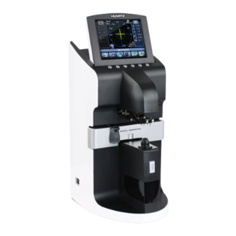
Introduction 1.1. Outline of the instrument The Automatic Lensmeter HLM-7000 is the equipment for measuring the refractive power of lenses and gives the spherical, cylindrical and axis of the lenses. The Automatic Lensmeter HLM-7000 also contains the PD(=pupil distance) measurement and the UV Protection Ratio Test. The automatic lensmeter HLM- 7000 can measure both the uncutted singular lenses and the framed glasses. -
Page 7: Safety Information
------------------------------------------------------------------------------ HLM-7000 User Guide Safety Information 2.1. Introduction Safety is everyone’s responsibility. The safe use of this equipment is largely dependent upon the installer, user, operator, and maintainer. It is imperative that personnel study and become familiar with this entire manual before attempting to install, use, clean, service or adjust this equipment and any associated accessories. -
Page 8: Safety Symbols
HLM-7000 User Guide -------------------------------------------------------------------------- INFORMATION “Information” each page will briefly describe the information being requested and the browser will open with information relative to your position. 2.2. Safety Symbols The International Electrotechnical Commission (IEC) has established a set of symbols for medical electronic equipment which classify a connection or warn of any potential hazards. -
Page 9: Environment Factors
------------------------------------------------------------------------------ HLM-7000 User Guide 2.3. Environment factors Avoid the following environments for operation or storage Where the equipment is exposed to water vapor. Don’t operate an equipment with a wet hand. Where The temperature changes extremely. Normal operating temperature range is from 10C to 40C, Humidity is from 50% to 80%. - Page 10 HLM-7000 User Guide -------------------------------------------------------------------------- Don’t plug the AC power cord into the outlet Before the connection between devices of the equipment is completed. This can generate the defect. Where the equipment is subject to excessive shocks or vibrations Be careful not to be inserted dust, especially, metal..
-
Page 11: Safety Precautions
The equipment must be operated only by, or under direct supervision a properly trained and qualified person. Modifications of this equipment may only be carried out by Huvitz’s service technicians or other authorized persons. Customer maintenance of this equipment may only be performed as stated in the User’s Manual and Service Manual. - Page 12 This equipment may only be used together with accessories supplied by Huvitz’s. If the customer makes use of other accessories, use them only if their safe usability under technical safety aspects has been proved and confirmed by Huvitz or the manufacturer of the accessory.
-
Page 13: Features
6. Measuring progressive multi-focal lenses and general multi-focal lenses can be performed easily and rapidly. 7. HLM-7000 can measure soft contact lenses easily and accurately using the specialized mechanical jig and the display. 8. HLM-7000 supports gorgeous displays through the proper colored LCD. -
Page 14: Notes For Using The Instrument
HLM-7000 User Guide -------------------------------------------------------------------------- Notes for using the instrument Do not hit or drop the instrument. The instrument may be damaged if it receives a strong impact. The impact can damage the function of this instrument. So handle with care. - Page 15 ------------------------------------------------------------------------------ HLM-7000 User Guide That’s why this instrument should perform the Display Protection function for the display protection as well as the compensation of temperature. Don’t place anything on the lens cap when you wake up this instrument from the display protection state. That’s why this instrument should perform the compensation of temperature at the moment.
-
Page 16: Configurations
HLM-7000 User Guide -------------------------------------------------------------------------- Configurations 5.1. Main Unit 1. LCD Display 2. Key Button 8. Marker Lever 3. PD Sensor 9. Lens Table 4. Lens Holder 10. Table Lever 5. Lens Supporter 6. Memory Button 11. Printer Cover 7. UV Cover [Figure 1. - Page 17 ------------------------------------------------------------------------------ HLM-7000 User Guide 1. Power Switch [Figure 2. Component Names (II)] 2. Power Connector 3. Foot Switch Connector [Figure 3. Component Names (III)] 1. Power Switch 2. Power Connector 3. Foot Switch Connector ОсОО «МЕДОФФ» www.medoff.net...
-
Page 18: Accessories
HLM-7000 User Guide -------------------------------------------------------------------------- 5.2. Accessories Printing Paper : Rolled paper for printing Fuse(250V 3.15A) : (2ea) Blower : A blower for removing dust on a pinhole Power Cord(Angle Type) Filter Cap : Cap for protection against dust (2ea) Tweezers : A kind of tool to pick up the contact lens Operator’s Manual : Operator manual for users... -
Page 19: Settings And Preparation For Operating
------------------------------------------------------------------------------ HLM-7000 User Guide Settings and Preparation for Operating 6.1. Receiving inspection Step 1. Checking accessories. Open the box and make sure that all the accessories (printing paper, protection cover, soft cloth for a lens, user’s manual) are in it Step 2. -
Page 20: Display Protection Function
HLM-7000 User Guide -------------------------------------------------------------------------- Turn on the machine. Make sure that there is nothing on the lens cap. If you encounter the message “No Signal” or “Out of range”, please clean the 4- pin hole. And then turn on again. -
Page 21: Buttons For Operations
------------------------------------------------------------------------------ HLM-7000 User Guide Buttons For Operations 7.1. Switching Screen According To the Button Selection Normal Lens Mode Progressive Lens Mode Soft Contact Lens Mode Hard Contact Lens Mode UV Lens Mode D-Sunglasses Lens Mode [Figure 5. Switching Screen According To the Button Selection]... -
Page 22: Usage Of Buttons
HLM-7000 User Guide -------------------------------------------------------------------------- 7.2. Usage of buttons MODE Setup Screen will be shown TRNS To transpose the sign of cylindrical reading PROG Enter the Progressive Multi-Focal Screen SOFT CNCT To go into the display for soft contact lens HARD CNCT To go into the display for hard contact lens ОсОО... - Page 23 ------------------------------------------------------------------------------ HLM-7000 User Guide To Enter the UV Measurement Screen D-SUN To measure the heavy dark sunglass lens LENS To return to the display for the normal lens S→R In case of single lens, you can switch between left and right selection of the...
- Page 24 HLM-7000 User Guide -------------------------------------------------------------------------- PRINT To print the current memorized data To set the current state of transmission into 100% To start recording the current data STOP To stop recording the current data and to memorized the average value MEM button To memorize the current measured-value ОсОО...
-
Page 25: Description Of Screen Layout
------------------------------------------------------------------------------ HLM-7000 User Guide Description of Screen Layout 8.1. Measurement Screen 1. Active Direction 4. Measuring point 5. Lens Type 2. Cylinder 3. Sequential No. 6. Measured Data 7. Message Box 11. Total PD 10. ABBE Data 8. State icon 9. -
Page 26: Detail Explanation
HLM-7000 User Guide -------------------------------------------------------------------------- 8.1.1. Detail explanation Active Direction ① Tells whether current lens is a single or a left/right lens. Cylinder ② Displays the cylinder value with (+) sign when the power has (+) value and with (-) sign when the power has (-) value Sequential No ③... - Page 27 ------------------------------------------------------------------------------ HLM-7000 User Guide Message Box ⑦ Notifies states of measurement and warnings and so on. ALIGNMENT OK : is displayed when the optical center falls within 0.5 prism. MARKING OK : is displayed when the optical center is ...
-
Page 28: About The Progressive Display
HLM-7000 User Guide -------------------------------------------------------------------------- 8.2. About the progressive display 1. Maximum ADD 2. Horizontal Guide Line 3. Measuring Point 4. Target for Far Vision 5. Addition [Figure 7. The display for the progressive powered lens] 8.2.1. Detail explanation Maximum ADD ①... -
Page 29: Uv Screen
------------------------------------------------------------------------------ HLM-7000 User Guide You should move the cross marker to the center of the target for far focus. Addition ⑤ This rectangle shows the current ADD value. 8.3. UV Screen 2. Current Transmission Ratio 3. Right 1. Left Transmission Ratio Transmission Ratio 4. -
Page 30: Contact Lens Display (Soft, Hard)
HLM-7000 User Guide -------------------------------------------------------------------------- Right Transmission Ratio ③ Shows the right-side stored value. Transmission Height ④ Shows the height of the current transmission height. 8.4. Contact Lens Display (Soft, Hard) 1. Signal 2. Start/Stop Record 3. Score Graph Of Each Point [Figure 9. -
Page 31: Detail Explanation
------------------------------------------------------------------------------ HLM-7000 User Guide 8.4.1. Detail explanation Signal ① Shows the share of every signal. Start/Stop Record ② Start : Start recording the continuous measurement. (Stop: Stop recording the continuous measurement, calculates the average value of all readings and then stores them. ) Score Graph for Each Point ③... -
Page 32: Setup Screen
HLM-7000 User Guide -------------------------------------------------------------------------- 8.6. Setup Screen [Figure 11. Setup Display] 8.6.1. Detail explanation LENS - NORMAL : normal lens - PROGRESSIVE : progressive lens - SOFT CONTACT : soft contact lens - HARD CONTACT : hard contact lens - UV... - Page 33 ------------------------------------------------------------------------------ HLM-7000 User Guide : always displays the cylinder value with (+) sign. : always displays the cylinder value with (-) sign. PROGRESSIVE AUTO - ON : auto detection of progressive lens. - OFF : turns off the progressive function.
- Page 34 HLM-7000 User Guide -------------------------------------------------------------------------- - XX : designated value for NORMAL ABBE(=50~60) └ MID XX - XX : designated value for MID ABBE(=40~49) └ LOW XX - XX : designated value for LOW ABBE(=30~39) DISPLAY - 5 P MODE : display unit 5 P.
- Page 35 ------------------------------------------------------------------------------ HLM-7000 User Guide RS-232C Selects the protocol of RS-232C - OFF : turns off the external communication - LMTORK(OLD) : turns on the protocol between HLM Model and MRK, HRK, CDR, HDR series. - LMTORK(V2) : turns on the bilateral protocol between HLM Model and MRK, HRK, CDR, HDR series.
- Page 36 HLM-7000 User Guide -------------------------------------------------------------------------- - ON(DEFAULT) : turns on the PD function - OFF : turns off the PD function - ON(AVERAGE ST.) : turns on the special PD function that makes the RPD and LPD even in case that the difference between RPD and LPD is less than 3mm.
- Page 37 ------------------------------------------------------------------------------ HLM-7000 User Guide - OFF : turns off the printing. AUTO PRINTER - ON : turns on the auto printing. - OFF : turns off the auto printing. INFORMATION If you take out the test lens from the lens cap after finishing the measurement, the measured data is automatically printed out.
-
Page 38: Printout Format
HLM-7000 User Guide -------------------------------------------------------------------------- EXIT Escapes with out saving. 8.7. Printout Format Printout format is as follows [Figure 12. Printout Format of Framed Glass] ОсОО «МЕДОФФ» www.medoff.net... -
Page 39: Measurements
------------------------------------------------------------------------------ HLM-7000 User Guide Measurements 9.1. Normal lenses [Figure 13. How To Measure a Normal Lens] Step 1 Press ‘CLEAR’ button( ) to initialize the state of measurement. The symbol ‘S’ must appear on the upper-right part of the screen. (But, ‘ AUTO R/L ’... - Page 40 HLM-7000 User Guide -------------------------------------------------------------------------- OFF center ALIGNMENT OK MARKING OK [Figure 14. Order for Focusing] Step 4 If the lens has astigmatism power, turn the lens so that the astigmatism angle become 180°. INFORMATION You don’t have to control astigmatism power to 180°if there is no astigmatism power or you have no plan to mark astigmatism focus and cylindrical axis.
- Page 41 ------------------------------------------------------------------------------ HLM-7000 User Guide value will be memorized. INFORMATION ‘ AUTO MEASURE ’ function is turned on in ‘ SETUP ’mode, ‘ MARKING OK ’ will be shown. And if you keep the state without any action more than 1 second, the measured data will be memorized automatically.
-
Page 42: Framed Lenses
HLM-7000 User Guide -------------------------------------------------------------------------- INFORMATION In case of a lens with power, the figure on the left bottom of the screen will display lens support with lens. CAUTION Move lens gently and softly with care. After placing the lens on the lens support, Lower-directed impact or sudden moving might result in the scratch or crack of the lens. - Page 43 ------------------------------------------------------------------------------ HLM-7000 User Guide Step 1 Press the ‘S->R’ button( ) to enter the measuring framed lens environment. Then, ‘L’ and ‘R’ will be shown on the upper-left and upper- right of the screen. CAUTION The current measuring right lens is the side of background is highlighted with cyan color and current measuring left lens is the side of background is highlighted with violet color.
- Page 44 HLM-7000 User Guide -------------------------------------------------------------------------- Step 7 Press the ‘MEM’ button to store the measured data and press the ‘PRINT’ button ( ) to print them. INFORMATION If you don’t want the PD value, you can use the lens table and the horizontal support without using the PD location sensor.
-
Page 45: Progressive Multi-Focal Lenses
------------------------------------------------------------------------------ HLM-7000 User Guide 9.3. Progressive Multi-Focal Lenses 9.3.1. The structure of progressive powered lens The Uncut Lens Lens Table Eye point mark for near Eye point mark for distance(=far) [Figure 17. The structure of single lens] INFORMATION The lens should be placed with its horizontal marks parallel to the lens table. -
Page 46: Judging Progressive Lens
HLM-7000 User Guide -------------------------------------------------------------------------- < The Mounted Lens > [Figure 18. The structure of the typical progressive frame lens] INFORMATION The dimension of progressive powered lens depends on the specification of manufacture. INFORMATION The old type progressive lens may not observe the 2~3mm shift toward the frame center. - Page 47 ------------------------------------------------------------------------------ HLM-7000 User Guide 9.3.2. Judging progressive lens Step 1 Make sure that the icon in the left bottom of display is in the standard mode as picture. Step 2 Place the lens over the lens cap and wait 1~2 seconds.
-
Page 48: Measuring A Progressive Lens For Far Vision Power
HLM-7000 User Guide -------------------------------------------------------------------------- INFORMATION Automatic Detection may not be available in case the progressive power is less than 1D. If so, press ‘PROG’ button( ) for progressive measurement. INFORMATION If the lens is not properly placed in Step 2, the normal lens icon (as picture) will be displayed in Step 3. -
Page 49: Measuring A Progressive Lens For Near Vision Power
------------------------------------------------------------------------------ HLM-7000 User Guide INFORMATION Do not lift up the lens by hand at the time of measurement. Place the lens holder over the lens in order to hold the lens by foot. Then move the lens forward/backward or left/right for measurement. Lifting up the lens may cause the error in the measurement. - Page 50 HLM-7000 User Guide -------------------------------------------------------------------------- INFORMATION In case the horizontal indicator is out of the tolerance range, move the right lens to right (left lens to left), since the near focus is located at 2~3mm toward the center of frame. Step 2 Pull the lens till the vertical indicator for near focus reaches to the criteria for near focus.
-
Page 51: Troubleshooting For Progressive Measurement
------------------------------------------------------------------------------ HLM-7000 User Guide INFORMATION The old type progressive lens may not observe the 2~3mm shift toward the frame center. 9.3.5. Troubleshooting for p 9.3.6. rogressive measurement ① Do not detect the progressive lens automatically Cause 1 : Lens holder is not located in the progressive area (Normal lens icon will be displayed in the left bottom of display.) - Page 52 HLM-7000 User Guide -------------------------------------------------------------------------- ④ Difficult to detect the near vision focus Cause 1 : The near focus is close to the lower frame Solution : Pull the lens a little bit more while lifting up the lens holder in order to detect the near focus.
-
Page 53: General Multi-Focal Lenses
------------------------------------------------------------------------------ HLM-7000 User Guide 9.4. General Multi-focal Lenses 9.4.1. Measuring at the Normal Display Step 1 Press the ‘ MEM ’ button after placing the lens over the first focus. Step 2 Press the ‘ MEM ’ button after placing the lens over the second focus. The first ‘ADD’... -
Page 54: Soft Contact Lenses
HLM-7000 User Guide -------------------------------------------------------------------------- INFORMATION At every step, in case that automatic measurement isn’t done or you want a manual decision, please press the ‘ MEM ’ button 9.5. Soft Contact Lenses We have to prepare the mechanical jig for measuring a soft contact lens. The procedures to measure a soft contact lens are as followings. -
Page 55: Hard Contact Lenses
------------------------------------------------------------------------------ HLM-7000 User Guide 9.6. Hard Contact Lenses Step 1 Select the ‘HARD CONTACT’ after choosing the ‘LENS’ item in the setup screen. Step 2 Wipe off the water and place the lens with its convex surface down. Step 3 Press the ‘MEM’ button to store the measured data and press the ‘PRINT’... -
Page 56: D-Sunglasses Lenses
HLM-7000 User Guide -------------------------------------------------------------------------- Step 1 Select the ‘UV’ after choosing the ‘LENS’ item in the setup screen. Step 2 Pull and extract the UV cover. Step 3 Press the ‘CAL’ button( ) to calibrate the transmission ratio into 100% if it is not. -
Page 57: Marking Focus And Cylindrical Axis
------------------------------------------------------------------------------ HLM-7000 User Guide 9.9. Marking Focus and Cylindrical Axis 9.9.1. When there is no astigmatism Step 1 Place the lens and control the lens so that it becomes ‘MARKING OK’ Step 2 Turn the Marking lever, which is vertical, by 90° to make it horizontal. And then, mark focus and cylindrical axis. -
Page 58: When There Is Astigmatism
HLM-7000 User Guide -------------------------------------------------------------------------- 9.9.2. When there is astigmatism Step 1 Place the lens and control the lens so that it becomes ‘MARKING OK’. Step 2 Keep ‘MARKING OK’ and control lens up to the angle of prescription slip. Step 3 Turn the Marking lever, which is vertical, by 90° to make it horizontal. And then, make marking focus and cylindrical axis. -
Page 59: Maintenance
------------------------------------------------------------------------------ HLM-7000 User Guide 10. Maintenance 10.1. Replacing Printing Paper [Figure 24. How to Replace the Printing Paper] Step 1 Open the printer cover. Step 2 Insert the paper into the printer shaft and put the shaft into the pre-defined position. -
Page 60: Replacing Fuse
Step 1 Pull out the fuse box. Step 2 Replace the old one with the new one. Step 3 Put into the fuse box with the new one. INFORMATION Use 250V, T3.15AL fuse for the Auto Lensmeter HLM-7000. ОсОО «МЕДОФФ» www.medoff.net... -
Page 61: Storage
------------------------------------------------------------------------------ HLM-7000 User Guide 10.3. Storage During night time, be sure to cover the dust cover as the below picture, because some dust might make spoil your equipment. [Figure 26. Storage for night time] If you don’t use your equipment for one week or more, make sure that the dust cap should be fitted into the lens cap as the below picture. -
Page 62: Disposal
HLM-7000 User Guide -------------------------------------------------------------------------- 10.4. Disposal NOTE To dispose the instrument, accessories, and components, follow local governing ordinances and recycling plans regarding disposal or recycling of instrument or device components. Especially a lithium battery may pollute the environment if the instrument or a lithium battery is abandoned. -
Page 63: Troubleshooting
------------------------------------------------------------------------------ HLM-7000 User Guide 11. Troubleshooting 11.1. Various Messages Message box shows information when you are measuring or this instrument is out of order. Here is the description on messages that appear in measuring. ALIGNMENT OK : When the optic center falls within 0.5 prism. - Page 64 Never use liquids such as alcohol, acetone, etc. Because such liquids might melt the glue on the 4-pin hole. After that, if the message “No Signal” or “Out of range” isn’t be disappeared, please ask to your local distributor or the Huvitz service department. ОсОО «МЕДОФФ» www.medoff.net...
-
Page 65: Specifications
------------------------------------------------------------------------------ HLM-7000 User Guide 12. Specifications Specification Table Measurement Range Sphere Power -25D ~ +25D Cylinder Power 0 to ±10.00D Cylinder Axis ~ 180 degrees(1 Step) Add Power 0 to +10D Prism Power 0 to 10 Precision Diopter Steps 0.01 / 0.125 / 0.25D Prism Power 0.01 / 0.125 / 0.25... - Page 66 HLM-7000 User Guide -------------------------------------------------------------------------- TFT LCD Display Display (320X240 LED Backlight) Data Output RS-232C, Printer 9600,19200,38400,57600,115200 bps 190(W) x 237(D) x 377(H) mm Dimensions 7.48 in. x 9.33 in. x 14.84 in. Weight 5.5Kg Power Supply AC 100 - 240 V ~, 50~60Hz, 1A...
-
Page 67: Service Information
------------------------------------------------------------------------------ HLM-7000 User Guide 13. Service Information How to contact service: If there are any problems with the equipment, please follow the steps below: First of all, refer to the 10. Maintenance and 11. Troubleshooting sections according to the problem that you are encountered. And then follow the suggested sequences. - Page 68 If you can’t contact with your local distributor, you can directly get in touch with the service department of the HUVITZ using the phone number and the address written in the below table. How to Contact HUVITZ Co., Ltd...
Need help?
Do you have a question about the HLM-7000 and is the answer not in the manual?
Questions and answers