Table of Contents
Advertisement
Advertisement
Table of Contents

Related Manuals for Huvitz CLM-3100P


Summary of Contents for Huvitz CLM-3100P
- Page 1 Service Manual Auto Lensmeter CLM-3100P Huvitz Co., Ltd.
-
Page 2: Table Of Contents
INDEX 1. INTRODUCTION................... 4 1.1.........................4 OMPONENTS 1.2........................6 EPAIR ROCEDURE 1.3............................7 AUTIONS 1.4. ROM I .................7 ISPLAY AYOUT FOR NFORMATION 1.5...........................7 PTICAL YSTEM 1.6......................9 EASUREMENT RINCIPLE CHECKING AND SETUP METHOD..........10 2.1..........................10 ETUP RDER 2.2. H ........................ - Page 3 Auto Lensmeter CLM-3100P 4.3 LCD TEST............................49 4.4. LED TEST ............................50 4.5. UV MODULE TEST ........................51 4.6. PD TEST.............................52 4.7. THERMAL PRINTER TEST .....................53 5. HOW TO UPGRADE THE OS PROGRAM ........54 5.1 I ..........................54 NTRODUCTION 5.2 I ....................55 NSTALLATION AND NINSTALLATION 5.3 U...
-
Page 4: Introduction
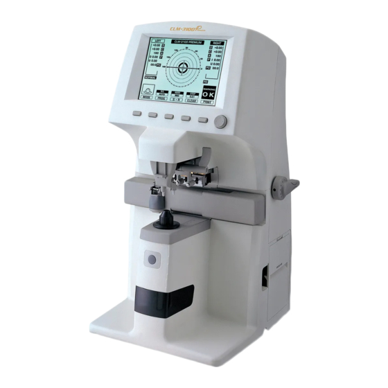
Introduction 1.1. Components List Figure 1. Components Names (I) - Page 5 Auto Lensmeter CLM-3100P Foot Switch Connector Interface Connector Power Switch Figure 2. Components Names (II) Power Conncentor Figure 3. Components Names (III)
-
Page 6: Repair Procedure
1.2. Repair Procedure Power ON 1. Examining the Internal Components First 2. Inspecting Thevalue, S.C.A. Prism Normal State Checking Abnormal State Cleaning the 4 Pinhole Power off and on Normal State Checking Abnormal State Setup Again Exit... -
Page 7: Cautions
Auto Lensmeter CLM-3100P Cautions 1.3. Always protect this instrument with Dust Cover after using. Do not vibrate or drop this instrument; it can cause damage. Use soft cloth or cotton swaps with alcohol when clean the 4 pinhole. Display 1.4. - Page 8 Receiving Light Part 2-dimentional CMOS sensor : converts four signals into digital value. Emitting light part and receiving light part also built optical system for UV measurement. One is composed of UV lamp and the other receives UV light. The wavelength of the UV light is 370nm.
-
Page 9: Measurement Principle
Auto Lensmeter CLM-3100P Measurement 1.6. Principle Basic Principle When there is no lens (0D state), parallel light that has transmitted the collimator lens passes the 4 pinhole and makes image on CCD. In case of convex lens (lens with plus diopter), parallel light that has transmitted the collimator lens converges through the measuring lens, passes the 4 pinhole and then makes image on CCD. -
Page 10: Checking And Setup Method
2. Checking and Setup Method 2.1. Setup Order When you turn on the power switch, you should hear the beep sound and see the ROM information. At this point, press the three buttons in the right side one after another from the rightmost one. Then, after the beep sound, your lensmeter, CLM3100P will start in setup and check mode. -
Page 11: How To Set Origin
Auto Lensmeter CLM-3100P 2.2. How to Set Origin Press the ‘CLEAR’ button for a while (2~3 seconds). And then press the ‘MEASR’ button. Next, determine the lens to measure (0D) by using left two arrow buttons in the following screen. Go ahead and calibrate by using two arrow buttons in the right side. - Page 12 AUTO-LENSMETER...
-
Page 13: How To Set Prism
Auto Lensmeter CLM-3100P 2.3. How to Set Prism When prism power does not fall in the range ±0.01 referred to the given value in the standard model-eye specification although you place the 2∆ lens from the standard lens set, you should set it up again. -
Page 14: How To Set 12 Standard Lenses
2.4. How to Set 12 standard lenses If the measured value is not accurate, you should set the diopter variables again by using the standard lens-set: for all the 12 lenses in the standard lens set. Always keep the standard lens clean out of dust or stain. S –D.00 C +0.00 A 180... -
Page 15: How To Set The Right/Left Switching Position Of Pd
Auto Lensmeter CLM-3100P 2.5. How to Set the Right/left Switching Position of PD You should specify the encoder position that the PD sensor(=nose) exactly lies on the center of the lens cap. Fix the PD sensor on the origin and turn on the power switch. -
Page 16: Diopter Setting Variables List
2.6. Diopter Setting Variables List The followings are diopter setting variables list: DISP SCREEN INFORMATION CEN : (+3.03.0446, +209.79) : center of the four points in 0D state. 0th: L=194.24; 1.00, 1.00, 1.00, 1.00 : average distance and distance rates between the four points and -25D -25D 1th: L=183.25;... -
Page 17: The Calibration Of The Cylindrical Axis
Auto Lensmeter CLM-3100P 2.7. The calibration of the cylindrical axis With the rectangular cylindrical lens, we can calibrate the cylindrical axis of our machine. The procedures are as followings: Place the rectangular cylindrical lens on the lens cap. Locate it to the center while cling it to the lens table like the following picture. -
Page 18: 5D Setup For The Progressive Measurement
2.8. –5D setup for the progressive measurement For measuring the accurate for the high powered progressive lens, it is needed to calibrate with –5D lens, which you can get easily the normal glass store. The procedures are as followings : Locate the lens to the center. -
Page 19: Repair Standard
Auto Lensmeter CLM-3100P 3. Repair Standard 3.1. Removing Body rear cover assembly... - Page 20 Component Removal method - First, separate 'Knob 1' from 'Knob pin 2' using M3 set Knob screw lench Body rear cover - Next, separate 'Knob pin 2' unscrewing two M2.6X8L. Cnnt bracket RS 232c - Remove six screws at the back cover, and then separate Foot switch all screws at the bottom frame.
-
Page 21: Removing Body Front Cover (Upper)
Auto Lensmeter CLM-3100P 3.2. Removing Body front cover (Upper) - Page 22 Component Removal method - Let's separate the 'Body front cover(Upper)'. First, Body front cover(Upper) remvoe 4 screws. TFT-LCD PCB cover - Next, remove 4 spring screws at the TFT-LCD 2' and Button PCB separate the 'Body front cover(Upper)' and the body. Button Brightness knob - Remove 4 M2X8L screws at the 'Button PCB 4'and...
-
Page 23: Removing Printer Assembly
Auto Lensmeter CLM-3100P 3.3 Removing Printer assembly... - Page 24 Component Removal method - First, remove the 'Printer case' with unscrewing Printer case M2X5L screws. Printer PCB Printer cover - Remove the M2 tappng screws and separate the Printer paper 'Printer PCB' and the 'Printer case'. Printer holder Printer header - Separate the 'Printer cover' and the 'Printer case' and take out the 'Printer paper 4' and the 'Printer holder 5'.
-
Page 25: Removing Pd Assembly
Auto Lensmeter CLM-3100P 3.4 Removing Pd assembly... - Page 26 Component Removal method - We have to separate the 'PD assembly', the 'Ink assembly' PD assembly and the 'PD guide cover' from the body. PD shaft1 PD shaft2 - Unscrew the 'PD shaft2,3' from the 'PD shaft(1).(2)' and PD main connect separate the 'PD main connector 4'.
- Page 27 Auto Lensmeter CLM-3100P 3.4.1 Removing Pd sub assembly...
- Page 28 Component Removal method - Remove the 'PD lock 3' and take apart the 'PD support PD case bracket' through removing M3X6L dish-head screws PD cover and pull out the 'Nose shaft 5' and separate parts PD lock No 6, 7, 8 sequencially. PD support bracket Nose shaft - Separate the 'PD frame' through removing the M3X6L...
-
Page 29: Removing Body Front Cover(Lower)
Auto Lensmeter CLM-3100P 3.5 Removing Body front cover(Lower) - Page 30 Component Removal method - First, remove 4 M3X10L screws at the 'Frame' and Body rear cover(Lower) separate the 'Body rear cover'. Filter cover Filter cover(Upper) - Remove the 'Filter cover 2', the 'Filter cover(Upper)' UV cover and the 'UV cover' from the 'Body front cover'. Membrane switch Membrane switch sticker - Remove the 'Membrane switch' from the 'Body front cover'...
-
Page 31: Removing Uv Assembly
Auto Lensmeter CLM-3100P 3.6 Removing UV assembly... - Page 32 Component Removal method - Separate the 'UV cover(Lower) 1' from the UV cover(Lower) 'Frame support(UV)' through removing four M3X5L screws. UV bone UV led And then separate the 'UV LED 3', 'UV teflon 4', UV teflon(Upper) 'UV rec 5' and 'UV teflon(Lower) 6'. UV rec UV teflon(Lower) - Be careful not to bend the rec's pin when...
-
Page 33: Removing Movement Assembly
Auto Lensmeter CLM-3100P 3.7 Removing Movement assembly... - Page 34 Component Removal method - Separate 'Position support 1', 'Foot stopper 2', Position suppt 'Shaft support 3', 'Control position foot 4' and Foot stopper(Upper) 'Pen control support 5' sequencially. Shaft suppt Control position foot - At 'Control position foot 4' and 'Pen control support 5', Pen control suppt remove the 'Bush 6', the 'Position shaft 7', Bush(D0406)
-
Page 35: Removing Gear Assembly
Auto Lensmeter CLM-3100P 3.8 Removing Gear assembly... - Page 36 Component Removal method - Separate the 'Shaft guide 1' from 'Back bone' through Shaft guide removing M3X8L screws. Shaft holder Shaft nut - Remove the 'Shaft holder' by wrench for M3 Set screw. Band washer Gear washer - Separate the 'Gear nut 3', 'Band washer 4', Gear washer 'Teflon washer 5', 'Teflon washer 6', 'Gear shaft 7' Gear shaft...
-
Page 37: Removing Main Board Assembly
Auto Lensmeter CLM-3100P 3.9 Removing Main board assembly... - Page 38 Component Removal method - Remove the 'Main board' from 'Frame' through Main board unscrewing four M3X5L screws. PCB support - Remove four PCB supports at 'Frame'. - Assembly is the reverse procedure of disassembly.
-
Page 39: Removing Back Bone Assembly
Auto Lensmeter CLM-3100P 3.10 Removing Back bone assembly... - Page 40 Component Removal method - First, separate the 'Back bone 1' and 'Frame' through Back bone removing four M3X8L screws. Back bone stopper - Separate the 'Back bone stopper 2' and 'Back bone' Back bone space through removing M4X8L screws. And remove the 'Back bone space'.
- Page 41 Auto Lensmeter CLM-3100P 3.10.1 Removing Lens housing bone and Led sub assembly...
- Page 42 Component Removal method - Separate the 'Lens housing bone' and 'Back bone' Lens housing bone through removing 4 M3X8L screws. CCD lens Lens housing bone retainer - Remove the 'Lens housing bone retainer 3', the LED housing 'CCD lens 2'. Pin hole(Upper) - Separate the 'LED housing' and 'Lens housing bone' Teflon scatter...
- Page 43 Auto Lensmeter CLM-3100P 3.10.2 Removing CCD Camera assembly...
- Page 44 Component Removal method - Separate the 'Filter housing 2' and 'Back bone' through Back bone removing M3 Set screws. Next, take apart the Filter housing '4 Pin hole' from the 'Filter housing'. 4 pin hole CCD cover - Separate the 'CCD holder 5' and 'Back bone', and CCD holder(Upper) remove the 'CCD holder' and 'CCD camera PCB ass'y' CCD holder...
-
Page 45: Removing Smps Assembly And Power Cover
Auto Lensmeter CLM-3100P 3.11 Removing SMPS Assembly and Power cover... - Page 46 Component Removal method - Separate the 'Power supply assembly' and the Frame 'Frame' through removing four M3X6L screws. Power supply ass'y Power socket - Remove the 'Power socket 3' through unscrewing Frame suppt(UV) two M3X5L screws. Power cover bracket Foot rubber - Separate the 'Power cover bracket 5' and the 'Frame' and 'Frame support(UV) 4' through removing four M3X5L screws.
-
Page 47: Electrical System
Auto Lensmeter CLM-3100P 4. Electrical System 4.1. MAIN BOARD PCB ASS’Y text text text THERMAL LEFT PHOTO PRINTER RIGHT PHOTO UV SEN IN ENCODER UV LED OUT FOOT S/W DC POWER MEM S/W LCD CCFL LCD DATA text text RS232... -
Page 48: Inspecting Smps
4.2 Inspecting SMPS Check1 . Check if POWER SWITCH and RUG is connected properly. Check2 . Check FUSE in POWER SOCKET with DMM. Check1 . Is Power LED on in SMPS MODULE? Check2 . Check the voltage of DC POWER Cable with DMM. Change SMPS MODULE (It should be AC100 or 220V) *REFERENCE: “ELECTRICAL CONSTRUCTION DIAGRAM”... -
Page 49: Lcd Test
Auto Lensmeter CLM-3100P 4.3 LCD TEST Measurement screen is not displayed… Check1 . SMPS TEST Check1. LCD is bright but there is no character Check if J12 connector of LCD is or figure. connected correctly to MAIN Check2 . There are horizontal lines on LCD and BOARD. -
Page 50: Led Test
4.4. LED TEST Cross mark (+) isn’t displayed in measurement waiting state… Check1 . Place white paper on FILTER COVER and Change LED module check if circular red right comes out from it. Check1 . Change MAIN BOARD PCB ASS’Y and test again. Change CCD module... -
Page 51: Uv Module Test
Auto Lensmeter CLM-3100P 4.5. UV MODULE TEST I cannot get UV-LED value… Check1 . Check if violet light radiated from OPTIC LED Change UV-LED PCB ASS’Y comes out from UV measurement part. UV-LED value in UV mode is 0%. Check1 . -
Page 52: Pd Test
4.6. PD TEST PD value is not displayed… Check1 . Check right/left switching when you move LEVER Change MAIN right and left compared to the center of PD. Change PD MODULE PD value is so strange… Check1 Check that PD LEVER is in initial position before you turn the power switch. -
Page 53: Thermal Printer Test
Auto Lensmeter CLM-3100P 4.7. THERMAL PRINTER TEST “PRT: HEAD UP” message is displayed on LCD… Check1. Open PRINTER COVER and check if HEADER LEVER towards upside. “PRT: PP EMPTY” message is displayed on LCD when pressing PRINTER BUTTON… Check1. Open PRINTER COVER. -
Page 54: How To Upgrade The Os Program
Lensmeter without sending and receiving it to the agency. This downloading program version 1.1 is specified to the Lensmeter, CLM-3100P model. If the version of a Lensmeter model is upgraded, this program might not work properly. Therefore, checking the version of your Lensmeter before installing this software is necessary. -
Page 55: Installation And Uninstallation
Auto Lensmeter CLM-3100P 5.2 Installation and Uninstallation A. Installation You can take the following steps to install this software. There is no preliminary condition and if you run the providing setup program, all the components required to communicate to the Lensmeter will be installed by default. - Page 56 ③ The next dialogue box will inquire the installation directory. You don’t have to change the default path but you can do so if there are some reason such as shortage of the disk space. [Figure 3] Change Destination directory dialogue box ④...
- Page 57 Auto Lensmeter CLM-3100P ⑤ Installation will be processed. All the programs needed will be copied to the predefined path and the system files such as dll and ocx to the Windows system path. After completing installation, you see the message as shown in [Figure 5].
- Page 58 B. Uninstallation Uninstallation follows the standard Windows uninstallation method. First, press the “Close” and “Exit” button to end the downloading program normally before uninstallation. And follow the below steps. ① Open Windows control panel and double click the “Add/Remove Programs” icon.
- Page 59 Auto Lensmeter CLM-3100P ② Select the “Downloading Program for CLM3000” in the “Install/Uninstall” tab as shown in [Figure 7]. And press the “Add/Remove…” button at the bottom of the screen. [Figure 7] Select “Downloading Program for CLM3000” in the “Install/Uninstall” tab ③...
- Page 60 ④ Now all the tasks are completed. Press the “OK” button in the application removal dialogue confirmation box [Figure 9]. [Figure 9] Application removal Confirmation dialogue box If you have taken these steps, application will be successfully removed.
-
Page 61: Usage
Auto Lensmeter CLM-3100P 5.3 Usage Now that installation is completed, let’s execute the downloading program. Press the “Start” menu and select the “Programs”. After that, execute the “Downloading Program for CLM3000” of the MiraeOptics program group as shown in [Figure 10]. After doing so, you should see the “Download”... - Page 62 To download the firmware image files to the Lensmeter, take the following steps. You should keep the order as follows. Otherwise, downloading might not be completed successfully. Notice that there are two firmware image files to be downloaded. One is for flash memory and the other is for main program. ①...
- Page 63 Auto Lensmeter CLM-3100P ③ Move to the next item, “3. Choose File & Download” and press the “…” button in “(1) Flash File” to choose the “almflash.bin” image file for flash memory. [Figure 13] Select Flash File dialogue box ④...
- Page 64 ⑤ Next, press the “…” button in “(2) Main File” of “3. Choose File & Download” item to select the image file for main program, “alm_main_bin”. [Figure 15] Select Main File dialogue box ⑥ Press the “Start” button in “(2) Main File” to start downloading main file. Hash mark will appear right after “STATUS:”...
- Page 65 Auto Lensmeter CLM-3100P [Figure 16] Completion message for downloading main image file...
-
Page 66: Troubleshooting
5.4 Troubleshooting Here are some hints for the troubles that might occur during downloading process. Before you contact your agency or Mirae Optics, check the following list carefully. ① Downloading program has no response. You should check that serial cable is connected to the specified COM port. - Page 67 Auto Lensmeter CLM-3100P firmware image files should be done again. ⑧ There are strange characters in the PROM log textbox. It might be the case that you run PROM mode before you enter the CONNECT mode. If so, switch off the power of the Lensmeter and do the download procedure again from the first step.
-
Page 68: Appendix
5.5 Appendix A. List of the installation package files Files including in the Lensmeter RS232 package are as follows: Rs232.cab: bundles of the files for installation Setup.exe: execution file for setup Setup.lst: list file including the list of the installation files and predefined path Firmware image files are not the accessories of this software.
Need help?
Do you have a question about the CLM-3100P and is the answer not in the manual?
Questions and answers