Table of Contents
Advertisement
Quick Links
Advertisement
Table of Contents

Related Manuals for Huvitz CLM-3100P


Summary of Contents for Huvitz CLM-3100P
- Page 1 Operator Manual Auto Lensmeter CLM-3100P Huvitz Co., Ltd.
-
Page 2: Table Of Contents
Contents 1. FEATURES.............................3 2. CAUTIONARY NOTES ........................5 3. COMPONENTS LIST AND FUNCTIONS..................6 3.1 M ............................6 3.2 A ............................9 CCESSORIES 4. SETTINGS AND PREPARATION FOR OPERATING ..............11 5. BUTTONS FOR OPERATIONS......................12 5.1 S ............12 WITCHING CREEN CCORDING O THE UTTON ELECTION 5.2 U ...........................12... -
Page 3: Features
1. Features (1) You can measure the center and refraction power of lenses with ease and rapidity. (2) In case of framed lens, single/binocular PD can be measured automatically in addition to the refraction power of each lens. (3) Transmission ratio of UV (Ultra Violet) light can also be measured with this CLM3000. -
Page 5: Cautionary Notes
2. Cautionary Notes (1) Handle with care this instrument. Unexpected impact may result in damage to the machine. (2) Install this instrument on a level, stabilized table with no vibration to keep it normal state. (3) Do not install this instrument where it might be exposed to the direct sunlight or too bright indoor light. -
Page 6: Components List And Functions
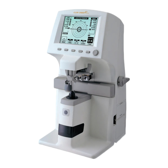
3. Components List and Functions 3.1 Main Unit... - Page 7 Figure 1. Component Names (I)
- Page 8 Foot Switch Connector Interface Connector Power Switch Figure 2. Component Names (II) Power Conncentor Figure 3. Component Names (III)
-
Page 9: Accessories
3.2 Accessories Figure 4. Accessories (1) Printing Paper Printing paper -----------------------------------------1 roll (2) Protection Cover Plastic cover for protection against dust-------------------------1 (3) Soft Cloth for a Lens A cloth for removing dust on a lens----------------------------1... - Page 10 (4) Lens Support General lens support---------------------------------------1 (5) Contact Lens Support Lens Support for contact lens--------------------------------1 The spherical radius of the contact lens’ cap support is equal with the average radius of hard contact lens. (6) Soft Lens Pad The Pad for measuring soft lens: tweezers, lens towel -------------1 (7) Foot Switch(Optional) The foot switch which replaces MEM button----------------------1 (8) User’...
-
Page 11: Settings And Preparation For Operating
4. Settings and Preparation for Operating Step 1. Checking accessories. Open the box and make sure that all the accessories (printing paper, protection cover, soft cloth for a lens, contact lens support, user’ s manual) are in it. Step 2. Removing the protection tape. Remove the protection tape from the lens holder, lens support, marking lever and the UV cover. -
Page 12: Buttons For Operations
5. Buttons For Operations 5.1 Switching Screen According To the Button Selection Basic Display1 S->R MODE PROG CLEAR PRINT Basic Display2 PRGA EXIT TRANS D-SUN S->R UV Display EXIT TRANS PRINT Setup Display Prog Display S->R MODE LENS CLEAR PRINT Figure 5. - Page 13 PROG ① Enter the Progressive Multi-Focal Screen. S>R ① In case of single lens, you can switch between left and right selection of the framed lens or you can select left /right lens. CLEAR ① To Initialize data and convert screen into the basic display 1. You can initialize data and screen by using this button.
- Page 14 ① To turn on/off temporarily the function of auto-detection for the progressive lens. ① To Enter the UV Measurement Screen. D-SUN ① To measure the heavy dark sunglass lens. ① To set the current state of transmission into 100%. MEM button ①...
-
Page 15: Screen Layout And Descriptions
. Screen Layout and Descriptions 6.1 Measurement Screen Figure 6. Screen Layout... - Page 16 1. Measured Data Box for displaying the measured data. Each meaning of the content is as shown below. S : basic power C : cylinder power A : cylinder axis P : prism X, prism Y PD : RPD or LPD AD : progressive power 1 and 2 2.
- Page 17 Tells whether current lens is a single or a left/right lens. 5. ‘ Press’ Button Name of the press button at lower part of the screen. See ‘ Usage of buttons’ . 6. Sign Of Cylinder When the highlighted ‘ TRNS’ is displayed on the screen, the sign of cylinder is also displayed inversion.
- Page 18 If you can see the figure with lens when there is no one, this instrument may be out of order. Then, please consult your agent. 9. ABBE Displays ABBE value applied. 10. Switching R/L When the ‘ PD’ is off after measuring the right lens, inserting the new lens yields converting into the left lens mode automatically.
- Page 19 Notifies states of measurement and warnings and so on. ALIGNMENT OK : is displayed when the optical center falls within 0.5 prism. MARKING OK : is displayed when the optical center is precise. And it tells that you can mark focus and cylindrical axis after you adjust the angle using the marking lever.
- Page 20 Especially the heavy dark sun-glass can’ t be properly measured. In this case, press the ‘ D-SUN’ button in ‘ Basic Display 2’...
-
Page 21: Progressive Multi -Focal Lens Screen
6.2 About the progressive display 1 Maximum additive value 2 Horizontal guide line 3. Vertical indicator 4 criteria for near focus 5 Target for far focus 6 Object 7. Horizontal indicator 8 Current ADD value Figure 7. The display for the progressive powered lens 1. - Page 22 3. Vertical indicator for near focus This vertical bar graph describes how far the current measuring point is from the near focus. 4. Criteria for near focus If the height of bar is less than triangular indicator, that’ s the near focus. 5.
- Page 23 This rectangle shows the current ADD value.
-
Page 24: Uv Screen
6.3 UV Screen 1.Trasnsmission Graph 2.Transmission Ratio UV: 12% Figure 8. UV Screen Layout 1. Transmission Graph Displays the transmission ratio in a bar graph form. 2. Transmission Ratio Transmission ratio (%) is displayed in numerical value. -
Page 25: Setup Screen
6.4 Setup Screen MENU E X I T O F F D I S P L A Y A U T O P R O G R E S S I V E P R O G R E S S I V E O N L Y F A R ME MO R Y... - Page 26 - NORMAL(PAD) : the situation that is used in the protection pad - SOFT CONTACT : soft contact lens - HARD CONTACT : hard contact lens DISPLAY - NORMAL : normal display PROGRESSIVE - OFF : turns off the progressive function. - AUTO : auto detection of progressive lens.
- Page 27 Initially, this system is ready for measuring the right lens. - ON-S/R/L : turns on auto decision of right or left lens. Initially, this system is ready for measuring the single lens. - OFF : turns off auto decision of right or left lens. BEEP - ON : turns on the beep sound function.
- Page 28 - X-Y : displays the prism information in X-Y coordinates. - P-B : represents the prism information with absolute distance and angle. - mm : displays the center difference in (x, y) coordinate by millimeter (mm). CYLINDER - MIX : displays the cylinder value with (+) sign when the power has (+) value and with (-) sign when the power has (-) value.
- Page 29 to the high-refractive lens. NORMAL - XX : designated value for NORMAL ABBE(=50~60) - XX : designated value for MID ABBE(=40~49) - XX : designated value for LOW ABBE(=30~39) WAVELENGTH - e-Line : displays the refractive power according to e-Line - d-Line : displays the refractive power according to d-Line AUTO OFF - YES...
- Page 30 RS-232C Selects the protocol of RS-232C - OFF : turns off the external communication - LMTORK : turns on the protocol between CLM-3000 Model and MRK, CDR series. Selects the speed of the external communication - 9600 - 19200 - 38400 - 57600 - 115200 SEQ.
- Page 31 PRINTER - On : turns on the printing. - Off : turns off the printing. AUTO PRINTER - On : turns on the auto printing. - Off : turns off the auto printing. If you take out the test lens from the lens cap after finishing the measurement, the measured data is automatically printed out.
- Page 32 NAME You can input the company name here. The company name will be displayed at the upper part of the printing paper. Select the input string by using the first and the second buttons from the left side and select the displaying position by the third and the forth button.
- Page 33 TIME To configure date and time. Select the input position by the left two buttons and increase/decrease the number by the third and the forth button. Pressing the Enter Key at the EXIT causes escape without saving and pressing the Enter Key at the End yields saving the changes.
-
Page 34: Printout Format
6.5 Printout Format Printout format is as follows Figure 10. Printout Format of Framed Glass... -
Page 35: Measurements
7. Measurements 7.1 Normal lenses Figure 11. How To Measure a Normal Lens Step 1 Press ‘ CLEAR’ button to initialize the state of measurement. ‘ SINGLE’ must appear on the upper-left part of the screen. Step 2 Place the lens on the support and lower the lens holder. Step 3 Move the cross mark of prism over the center of the concentric circles. - Page 36 Figure 12. Order for Focusing Step 4 If the lens has astigmatism power, turn the lens so that the astigmatism angle become 180°.
- Page 37 You don’ t have to control astigmatism power to 180 ° there is no astigmatism power or you have no plan to mark astigmatism focus and cylindrical axis. Step 5 Press ‘ MEM’ or ‘ Foot’ button to store the measured data. If the memorizing function is working, outer box enclosing data will be thicker and the data will be fixed.
- Page 38 lens support or there is one. without lens with lens Figure 13. Display the State of Measurement When there is no lens, you will see the figure on the left- bottom of the screen displaying lens support with no lens. If the figure displays lens support with lens but there is no one actually, consult your agent.
-
Page 39: Framed Lenses
moving might result in the scratch of the lens. 7.2 Framed lenses Figure 14. Measurement of Framed Lens Step 1 Press [S>R] button to enter the measuring framed lens environment. Then, ‘ LEFT’ and ‘ RIGHT’ will be shown on the upper-left and upper-right of the screen. - Page 40 The current measuring lens is the side of which background is black between ‘ LEFT’ ‘ RIGHT’ . Step 2 Place the right lens on the support and lower the lens holder. Step 3 Place the PD location sensor in the middle of the frame when PD function is on.
- Page 41 (option) is not supported, PD function is off, or ‘ AUTO R/L’ function is off. Step 6 Move the lens so that the ‘ MARKING OK’ appears (focusing). And place the PD location sensor in the middle of the frame when PD function is on.
- Page 42 origin position before turning on the power. In case that ‘ Auto R/L’ function is on and PD function is off, after the right lens is completed you should identify the ‘ No lens’ icon in the left bottom display. And then locate the left lens. In that case ‘...
-
Page 43: Progressive Multi-Focal Lenses
7.3 Progressive Multi-Focal Lenses 7.3.1 The structure of progressive powered lens The Uncut Lens Lens Table Eye point mark for near Eye point mark for distance(=far) Figure 15. The structure of single lens The lens should be placed with its horizontal marks parallel to the lens table. - Page 44 The Mounted Lens 2~3mm 2~3mm Figure 16. The structure of the framed lens The dimension of progressive powered lens depends on the specification of manufacture. The old type progressive lens may not observe the 2~3mm shift toward the frame center. Do not lift up the lens by hand at the time of measurement.
- Page 46 7.3.2 Judging progressive lens Step 1 Make sure that the icon in the left bottom of display is in the standard mode as picture. Step 2 Place the lens over the lens cap and wait 2~3 seconds. It is recommended to place the lens holder over the marked ) area (progressive powered band).
- Page 47 Figure 18. The changes of state icon Automatic Detection may not be available in case the progressive power is less than 1D. If so, press “ PROG” button for progressive measurement. If the lens is not properly placed in Step 2, the normal lens icon (as picture) will be displayed in step 3.
- Page 48 till the foot of lens holder reaches to the upper frame. Step 2 Adjust the lens left/right (horizontal) or forward/backward (vertical) in order to place the cross marker (+) at the center of target for far focus. Step 3 The power of far focus will be automatically detected and memorized with the beep sound in case the cross marker (+) is placed at the center properly.
- Page 49 the error in the measurement. The single Lens or the framed lens should be parallel to the lens table. 7.3.4 Measuring a progressive lens for near vision power Step 1 Move the lens to the near vision area. In case of framed lens, move the lens till the foot of lens holder reaches to the lower frame.
- Page 50 In case the horizontal indicator is out of the tolerance range, move the right lens to right (left lens to left), since the near focus is located at 2~3mm toward the center of frame. Step 2 Pull the lens till the vertical indicator for near focus reaches to the criteria for near focus.
- Page 51 press “ MEM” button to set the focus of near vision. (Measurement date may be a little bit different from the actual data). Case I Case II Figure 19. The small framed lens Do no lift up the lens by hand at the time of measurement. Place the lens holder over the lens in order to hold the lens by foot.
- Page 52 1) Do not detect the progressive lens automatically Cause 1 : Lens holder is not located in the progressive area (Normal lens icon will be displayed in the left bottom of display.) Solution : Move the lens to the progressive area for progressive measurement.
- Page 53 function in set-up display for system variable( Refer to Section 6.4 ). 3) Difficult to detect the far vision focus Cause 1 : The progressive area is expanded into the far vision focus Solution : Place the cross marker(+) at the close point to the center and press "MEM"...
- Page 54 whiling securing the tolerance range of horizontal indicator. Then press "MEM" button to set the focus of near vision in case the add power is maximized. (Measurement date may be a little bit different from the actual data). 5) Error in the measurement data (especially the lens over -4D of near vision power) Cause 1 : Lift up the lens by hand at the time of measurement Solution : Place the lens holder over the lens in order to hold the lens by foot.
- Page 55 Solution : Detect the maximized add value of the points.
-
Page 56: General Multi-Focal Lenses
7.4 General Multi-focal Lenses 7.4.1 Measuring at The Normal Display Step 1 Press the ‘ MEM’ button after placing the lens over the first focus. Step 2 Press the ‘ MEM’ button after placing the lens over the second focus. The first ‘... - Page 57 over the third focus area, press the ‘ ADD2’ button. At that time, the measurement is done automatically. At every step, in case that automatic measurement isn’ t done or you want a manual decision, please press the ‘ MEM’ button.
-
Page 58: Hard Contact Lenses
7.5 Hard Contact Lenses Step 1 Select the ‘ HARD CONTACT’ after choosing the ‘ LENS’ item in the setup screen. Step 2 Remove the lens support and install the contact lens suppport. Step 3 Wipe off the water and place the lens with its convex surface up. Step 4 Move the lens right/left and back/forth to focus. -
Page 59: Transmission Ratio Of Uv Light
7.7 Transmission Ratio of UV Light Figure 20. How To Measure Transmission Ratio of UV Light Step 1 Enter the UV Measurement Screen to press the ‘ MODE’ and the ‘ UV’ button continuously. Step 2 Pull and extract the UV cover. Step 3 Press the ‘... -
Page 60: Marking Focus And Cylindrical Axis
Step 5 Press the ‘ MEM’ button to memorize the transmission ratio and press the ‘ PRINT’ button for printing the measured data. 7.8 Marking Focus and Cylindrical Axis 7.8.1 When there is no astigmatism Step 1 Place the lens and control the lens so that it becomes ‘ MARKING OK’... -
Page 61: Prism
Figure 21. How To Mark Focus and Cylindrical Axis 7.8.2 When there is astigmatism Step 1 Place the lens and control the lens so that it becomes ‘ MARKING OK’ . Step 2 Keep ‘ MARKING OK’ and control lens up to the angle of prescription slip. - Page 62 8.1 Replacing Printing Paper Figure 22. How to Replace the Printing Paper Step 1 Open the printer cover. Step 2 Insert the paper into the printer shaft and put the shaft into the predefined position. Step 3 Lift the printer lever and insert the shaft with paper. Step 4 Lower the printer lever and turn the feeding velvet to roll the paper.
-
Page 63: Power Saving Function
8.2 Various Messages Message box shows information when you are measuring or this instrument is out of order. Here is the description on messages that appear in measuring. ALIGNMENT OK : When the optic center falls within 0.5 prism. MARKING OK : When the optic center is correct. - Page 64 automatically. In power saving mode, company symbol and product name will be enlarged/reduced dynamically. If you press any button on this mode, it will return to the measurement screen.
-
Page 65: Specifications
10. Specifications Specification Table Measurement Range 0 to Sphere Power ± 25D 0 to Cylinder Power ±10.00D Cylinder Axis – 180 degrees(1 Step) Add Power 0 to +10D 0 to 10Δ( 270 방향) Prism Power 0 to 4Δ(나머지 방향) Precision Diopter Steps 0.01 / 0.125 / 0.25D Prism Power... - Page 66 Contact Lenses Hard and soft Abbe Values Manual Compensation Wavelength e-Line d-Line LCD Display Display (320X240 LCD Backlight) Data Output RS-232C 9600,19200,38400,57600,115200 230 x 245 x 426 mm Dimensions 9.05 in. x 9.64 in. x 16.77 in. Weight Power Supply AC 100 - 240 V, 50~60Hz Options Internal Printer...
Need help?
Do you have a question about the CLM-3100P and is the answer not in the manual?
Questions and answers