Table of Contents
Advertisement
Quick Links
Advertisement
Table of Contents

Related Manuals for Huvitz CLM-9000


Summary of Contents for Huvitz CLM-9000
- Page 1 Service Manual Auto Lensmeter CLM-9000...
-
Page 2: Table Of Contents
Auto Lensmeter CLM-9000 INDEX INTRODUCTION ................3 1.1. C .......................... 3 OMPONENTS 1.2. R ........................5 EPAIR ROCEDURE 1.3. C ............................6 AUTIONS 1.4. S ........................6 OFTWARE VERSION 1.5. O ..........................6 PTICAL YSTEM 1.6. M ......................7 EASUREMENT RINCIPLE CHECKING AND SETUP METHOD .......... - Page 3 ....................... 38 LECTRICAL BLOCK DIAGRAM 4.3. I SMPS ........................39 NSPECTING 4.3. LCD TEST ............................ 40 4.4. LED TEST ............................ 41 4.5. UV MODULE TEST ........................42 4.6. PD TEST ............................43 4.7. THERMAL PRINTER TEST ....................... 44 HOW TO UPGRADE THE OS PROGRAM ......... 45 5.1.
-
Page 4: Introduction
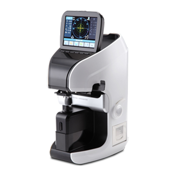
Auto Lensmeter CLM-9000 1. Introduction 1.1. Components List LCD Display Key Button Marker Lever PD Sensor Lens Table Lens Holder Table Lever Lens Support Printer Cover Memory Button UV Cover Figure 1. Components Names (I) - Page 5 Power Switch Figure 2. Components Names (II) Power Cable Figure 3. Components Names (III)
-
Page 6: Repair Procedure
Auto Lensmeter CLM-9000 1.2. Repair Procedure Power ON 1. Examining the Internal Components First 2. Inspecting The value, S.C.A. Prism Normal State Checking Abnormal State Cleaning the Pinhole Power off and on Normal State Checking Abnormal State Setup Again Exit... -
Page 7: Cautions
Cautions 1.3. ⚫ Always protect this instrument with Dust Cover after using. ⚫ Do not vibrate or drop this instrument; it can cause damage. ⚫ Use soft cloth or cotton swaps with alcohol when clean the 4 pinhole. Software OS version 1.4. -
Page 8: Measurement Principle
Auto Lensmeter CLM-9000 Measurement Principle Basic Principle When there is no lens (0D state), parallel light that has transmitted the collimator lens passes the pinhole and makes image on CMOS. In case of convex lens (lens with plus diopter), parallel light that has transmitted the collimator lens converges through the measuring lens, passes the pinhole and then makes image on CMOS. -
Page 9: Checking And Setup Method
ROM information. At this point, press the two buttons together in the third button and sixth button. Then, after the beep sound, your lensmeter, CLM-9000 will start in setup and check mode. The booting steps for‘SETUP’ mode are as follows: A. -
Page 10: How To 0D Setup
Auto Lensmeter CLM-9000 2.2. How to 0D Setup When there is lens mark or diopter/cylinder values without lens, Perform 0D setup A. Before 0D setup, clean LM lens and 81pin holes B. Press the ‘LENS SETUP’(button 1) C. Press the ‘MEASU’ button. -
Page 11: How To Set 12 Standard Lenses
2.3. How to Set 12 standard lenses If the measured value is not accurate, you should set the diopter variables again by using the standard lens-set: for all the 12 lenses in the standard lens set. Always keep the standard lens clean and out of dust or stain. A. -
Page 12: How To Set Prism
Auto Lensmeter CLM-9000 2.4. How to Set Prism If the measured value is not accurate, you should set the 2, 5, 10 lens again by using the standard lens-set. Lens value A. First, convert prism display format into X, Y. -
Page 13: The Calibration Of The Cylindrical Axis
2.5. The calibration of the cylindrical axis With the +1.5D and -1.5D cylindrical lenses, we can calibrate the cylindrical axis of the equipment. The procedures are as follows: Lens value A. Press‘CYL SETUP’button. B. Place the -1.5D cylindrical lens on the lens cap. C. -
Page 14: How To Set Pd
Auto Lensmeter CLM-9000 2.6. How to set PD PD calibration procedures are as follows: A. Press the ‘PD SETUP’button. B. Place the PD bar at the most left side. And press‘L Lim’ button. C. Place the PD bar at the most right side. And press ‘R Lim’ button. -
Page 15: How To Set Uv
2.7. How to set UV UV calibration procedures are as follows: A. Press ‘UV SETUP’ button. B. Open UV cover. C. Place UV lens on the UV sensor. For UV lens 0, place no lens. For UV lens 100, cover the UV sensor D. -
Page 16: How To Change The Led Assembly
Auto Lensmeter CLM-9000 2.8. How to change the LED Assembly The LED assembly is part of the Upper Frame. To replace LED assembly, whole Upper Frame should be replaced. The procedures for changing the upper frame Assembly are as follows: A. -
Page 17: How To Change The Pinhole Housing
2.12. How to change the Pinhole Housing The procedures for changing the Pinhole Housing are as follows: A. Take out the Lens Supporter. B. Remove the Pinhole Housing Cover C. Loosen and take out the screws in Upper Holes. D. Lift up the Pinhole Housing and replace it the new one. E. -
Page 18: Repair Standard
Auto Lensmeter CLM-9000 3. Repair Standard 3.1. Removing cover assembly... - Page 19 Component Removal method -Disassemble parts in following order LCD Assy - Loosen screws and detach [11] LED Bone Assy - Loosen screws and detach [9] Front UV Cover - Loosen screws and detach [5] Back Bone Assy - Loosen screws and detach [6] Left Out Cover - Loosen screws and separate [7] Right Out Cover...
-
Page 20: Disassembling Lcd Ass'y
Auto Lensmeter CLM-9000 3.2. Disassembling LCD ass’y... - Page 21 Component Removal method - Loosen screws on [1] LCD Back Cover LCD Back Panel - Remove [4] LCD Front Cover - Loosen screws on [6] and [7] LCD Fixer Hinge - Loosen screws on [2] and separate from [1] Hinge - Detach [3] and [5]...
-
Page 22: Removing Printer Ass ' Y
Auto Lensmeter CLM-9000 3.3. Disassembling Printer ass’y... - Page 23 Component Removal method - First, remove four screws that fix ‘APS Print Assy’ from the PR Body ‘Cover Right’. Thermal Printer B/D Then, separate it from the ‘Cover Right’ PR Open Cover PR Open Cover Holder - Next, disconnect [6]’s flat cable from [2]. Paper Holder Then, remove four screws that fix [2] and separate it.
-
Page 24: Removing Pd Assembly
Auto Lensmeter CLM-9000 3.4. Removing PD assembly... - Page 25 Component Removal method - Disconnect ‘PD Bar Board’ cable from ‘Main Board’. PD Bar Assembly O-Ring & Washer - Then, remove two screws that fix [4] from the [1]. Filter Housing Cap Then, separate it. Nose Assembly PD Bar Cover - Loosen screw on [2], remove from ‘PD Rack Gear Shaft’...
-
Page 26: Removing Uv Assembly
Auto Lensmeter CLM-9000 3.5. Removing UV assembly... - Page 27 Component Removal method - Remove from [1] UV Bone UV Sensor - Separate [2],[3] UV LED PCB UV Tefron (Upper) - Detach [4], [5] UV Tefron (Lower) - Assembly is the reverse procedure of disassembly.
-
Page 28: Removing Movement(Left) Subassembly
Auto Lensmeter CLM-9000 3.6.1. Removing Movement(Left) Subassembly... - Page 29 Component Removal method - Remove four screws to separate [1]’s sub assembly. Foot Frame Brk F T2 Control Pos Pin - Unscrew [2] by using the spanner. Foot Moving Block Guide Shaft 4 - Remove two screws to separate [7]~[10]’s sub Teflon Washer assembly.
-
Page 30: Removing Movement(Right) Subassembly
Auto Lensmeter CLM-9000 3.6.2. Removing Movement(Right) Subassembly... - Page 31 Component Removal method - First, remove two screws that fix [8]~[15]’s sub Pen Slide Base assembly. Slide Moving Block Slide Fix Block - Remove two screws to separate [9]~[15]. Slide Shaft Bearing Ball (Ø3) - Remove the ‘E-ring’ to separate [12]. Slide Guider And then separate [9], [10],[12], [13] and ‘Pen Pen Extension Spring...
-
Page 32: Disassemble Led Subassembly
Auto Lensmeter CLM-9000 Disassemble LED subassembly... - Page 33 Component Removal method - Remove four wrench bolts to separate ‘Lens housing LED Bone bone Assembly’ form the ‘back Bone Assembly’ LED Lens Nut - Unscrew [3], and then separate [4] LED Lens - Loosen 4 screws and remove [2] - Assembly is the reverse procedure of disassembly.
-
Page 34: Removing Cmos Camera Assembly
Auto Lensmeter CLM-9000 3.8.2. Removing CMOS Camera assembly... - Page 35 Component Removal method - Remove cables connecting [3] and [4] Back Bone Pin Hole - Loosen screws and remove [3] CMOS Camera B/D CMOS Interface B/D - Loosen screws and remove [4] - Loosen screws and [2] - Assembly is the reverse procedure of disassembly.
-
Page 36: Removing Smps Assembly And Power S/Wand Fuse Inlet
Auto Lensmeter CLM-9000 3.9. Removing SMPS Assembly and Power S/W and Fuse Inlet... - Page 37 Component Removal method - Remove two screws that fix [2], then separate it from Base Frame [1]. SMPS Fuse Inlet - Pull out [3], [4] from [1]. Power S/W RS232C - Remove two PCB Supports from [5]. Foot And then, separate [5]. - Finally, remove screws that fix [6].
-
Page 38: Electrical System
Auto Lensmeter CLM-9000 4. Electrical System 4.1. MAIN BOARD PCB ASS’Y [BT1] [CN12] [CN5] Lithum-Ion Battery Key Pad QVGA TFT LCD For Calendar [CN4] [CN19] RS-232 SVGA [CN1] Rom Socket [CN13] Connector Optic LED1 For factory. FLASH [CN15] FPGA [CN6]... -
Page 39: Electrical Block Diagram
Electrical block diagram... -
Page 40: Inspecting Smps
Auto Lensmeter CLM-9000 4.3. Inspecting SMPS Check1 . Check if POWER SWITCH and RUG is connected properly. Check2 . Check FUSE in POWER SOCKET with DMM. Check1 . Is Power LED on in SMPS MODULE? Check2 . Check the voltage of DC POWER Cable with DMM. -
Page 41: Lcd Test
4.3. LCD TEST ⚫ Measurement screen is not displayed… Check1 . SMPS TEST Check1. LCD is bright but there is no character Check if CN5 connector of LCD or figure. Check2 . There are horizontal lines on LCD and connected correctly to MAIN screen display is malfunctioned. -
Page 42: Led Test
Auto Lensmeter CLM-9000 4.4. LED TEST ⚫ Cross mark (+) isn’t displayed in measurement waiting state… Check1 . Place white paper on FILTER COVER and Change LED module check if circular green light comes out from it. Check1 . Change MAIN BOARD PCB ASS’Y and test again. -
Page 43: Uv Module Test
4.5. UV MODULE TEST ⚫ I cannot get UV-LED value… Check1 . Check if violet light radiated from OPTIC LED Change UV-LED PCB ASS’Y comes out from UV measurement part. ⚫ UV-LED value in UV mode is 0%. Check1 . Check if UV SENSER in UV measurement part is hidden by obstacles such as FILTER COVER . -
Page 44: Pd Test
Auto Lensmeter CLM-9000 4.6. PD TEST ⚫ PD value is not displayed… Check1 . Check right/left switching when you move LEVER Change MAIN right and left compared to the center of PD. BOARD Change PD MODULE... -
Page 45: Thermal Printer Test
4.7. THERMAL PRINTER TEST ⚫ “PRT: HEAD UP” message is displayed on LCD… Check1. Open PRINTER COVER and check if HEADER LEVER towards upside. ⚫ “PRT: PP EMPTY” message is displayed on LCD when pressing PRINTER BUTTON… Check1. Open PRINTER COVER. Check2. -
Page 46: How To Upgrade The Os Program
5. How to upgrade the OS program 5.1. Introduction Downloading program for CLM-9000 with RS232 cable (Lensmeter RS232) provides downloading function of the firmware software from PC to Lensmeter, CLM-9000 with serial cable. An administrator of the Lensmeter hardware can receive the Firmware by e-mail or else and load it to lensmeter by this downloading program when the new upgrade version of firmware comes out. -
Page 47: How To Upgrade The Os Program Using Dnw Application In Clm Machines
5.2. How to upgrade the OS program using DNW application in CLM Machines A. Copy the DNW application files. DNW consists of two files : the executable file(= dnw.exe), the configuration file(= dnw.ini ). It is no need to install it in your desktop computer. - Page 48 Auto Lensmeter CLM-9000 D. Click the Connect item in the Serial Port menu to open the specified serial port. After succeeding in opening the serial port, the title of DWN application shows the Com port and the Baud Rate on the title bar.
- Page 49 finally you can see the screen as following : Finally turn off and on the machine.
Need help?
Do you have a question about the CLM-9000 and is the answer not in the manual?
Questions and answers