Table of Contents
Advertisement
Advertisement
Table of Contents

Related Manuals for Huvitz HRK-8000A


Summary of Contents for Huvitz HRK-8000A
- Page 1 Service Manual Auto Ref/Keratometer HRK-8000A...
- Page 2 HUVITZ reserves the right to make changes in its products or product specifications at any time and without prior notice, and is not required to update this documentation to reflect such...
- Page 3 HUVITZ reserves the right to make changes in its products or product specifications at any time and without prior notice, and is not required to update this documentation to reflect such changes.
-
Page 4: Table Of Contents
---------------------------------------------------------------------------------------------- Auto Ref/Keratometer HRK-8000A 3 Contents I. Important Notice ................. 4 II. Safety Information ................54 1. Introduction ................54 2. Safety Symbols ................6 3. Environment Factors ..............7 4. Safety Precautions ............... 9 III. Product Outline ................11 1. -
Page 5: Important Notice
Huvitz reserves the right to make changes in its products or product specifications at any time and without prior notice, and is not required to update this documentation to reflect... -
Page 6: Safety Information
---------------------------------------------------------------------------------------------- Auto Ref/Keratometer HRK-8000A 5 2.Safety Information 2.1.Introduction Safety is everyone‟s responsibility. The safe use of this equipment is largely dependent upon the installer, user, operator, and maintainer. It is imperative that personnel study and become familiar with this entire manual before attempting to install use, clean, service or adjust this equipment and any associated accessories. -
Page 7: Safety Symbols
6 Auto Ref/Keratometer HRK-8000A ------------------------------------------------------------------------------------------------ 2.2.Safety Symbol The International Electro technical Commission (IEC) has established a set of symbols for medical electronic equipment, which classify a connection or warn of any potential hazards. The classifications and symbols are shown below. - Page 8 ---------------------------------------------------------------------------------------------- Auto Ref/Keratometer HRK-8000A 7 2.3.Environmental Considerations Please avoid the environment below for the operation and storage of the equipment Where equipment Where the machine can exposed to water vapor. exposed chemical or flammable Don‟t operate the equipment substances. with wet hands.
- Page 9 8 Auto Ref/Keratometer HRK-8000A ------------------------------------------------------------------------------------------------ For the normal operation of the machine, please keep the ambient temperature is 10℃ ~ 35℃, humidity is 30% ~ 75% and atmospheric pressure is 800 ~ 1060hpa. For the Transformation of the machine, please keep the ambient temperature is -40℃...
-
Page 10: Safety Precautions
The manufacturer is not liable for damage caused by unauthorized tampering with the device(s). Such tampering will forfeit any rights to claim under warranty. The equipment may only be used together with accessories supplied by Huvitz‟s. If the customer makes use of other accessories, use them only if there are usability under... - Page 11 10 Auto Ref/Keratometer HRK-8000A ------------------------------------------------------------------------------------------------ technical safety aspects has been proved and confirmed by Huvitz or the manufacturer of the accessory. Only persons who have undergone proper training and instructions are authorized to install, use, operate, and maintain this equipment.
-
Page 12: Product Outline
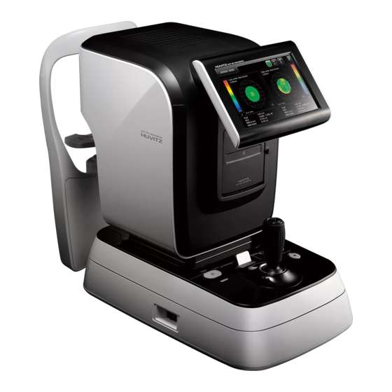
---------------------------------------------------------------------------------------------- Auto Ref/Keratometer HRK-8000A 11 3.Product Outline 3-1. Nomenclature 1. Head Rest : Preventing the vibration by fixing the head 2. Measurement Button: Performing the measurement by pressing it after focusing 3. Operation Lamp : Indicates whether or not the electric power is on 4. - Page 13 12 Auto Ref/Keratometer HRK-8000A ------------------------------------------------------------------------------------------------ 1. Power Supply Socket : A socket connecting to exterior power plug 2. Serial Interface Connector : A terminal connecting to the exterior equipment 3. Exterior Monitor Connection Connector : Connecting into the exterior monitor 4.
-
Page 14: Optical System
---------------------------------------------------------------------------------------------- Auto Ref/Keratometer HRK-8000A 13 3-2.Optical System... - Page 15 14 Auto Ref/Keratometer HRK-8000A ------------------------------------------------------------------------------------------------ 3-2-1.List of Optical Components 1 : patient‟s eye 2-1, -2 : LED for lightening cornea 3-1, -2, : ring unit of the keratometry 4-1 : white LED 4-2 : blue LED 5-1 : half mirror...
- Page 16 ---------------------------------------------------------------------------------------------- Auto Ref/Keratometer HRK-8000A 15 3-2-2.Light Paths of the System A : External illumination ( 2- 1, 2- 2 1) B : Corneal observation system ( 1 5- 1 5 - 2 1 7 1 8 ) C : K er m eas ur em ent s ys tem ( 3- 1, 3- 2, ...
-
Page 17: Electrical System
16 Auto Ref/Keratometer HRK-8000A ------------------------------------------------------------------------------------------------ 3-3.Electrical System 3-3-1.Electrical construction diagram 3-3-1-1.System functional block diagram SMPS DC Output +5V, 4A Output +5V, 2A +12V, 1.8A Dual Line Fuse DC12V Power switch AC 100-240~ (DPST) SMPS Motor Board Power & Signal 8.3A... - Page 18 ---------------------------------------------------------------------------------------------- Auto Ref/Keratometer HRK-8000A 17 3-3-1-2.Power input electrical block diagram SMPS Output DC Output +5V, 4A DC12V +5V, 2A +12V, 1.8A 8.3A Dual Line Fuse Power switch AC 100-240~ (DPST) SMPS...
- Page 19 18 Auto Ref/Keratometer HRK-8000A ------------------------------------------------------------------------------------------------ 3-3-2.Electrical wiring 3-3-2-1.Main Board SRAM FPGA SRAM SDRAM SRAM SRAM FLASH...
- Page 20 ---------------------------------------------------------------------------------------------- Auto Ref/Keratometer HRK-8000A 19 3-3-2-2.Description of wire harness connection of main board Connect No. Description Target connector 1 (CN29) IO Board interface #1 Base Interface Board CN5 2 (CN12) Serial Port Not Connect 3 (CN14) USB Port Not Connect...
- Page 21 20 Auto Ref/Keratometer HRK-8000A ------------------------------------------------------------------------------------------------ 3-3-2-3.Base IO Interface Board...
- Page 22 ---------------------------------------------------------------------------------------------- Auto Ref/Keratometer HRK-8000A 21 3-3-2-4.Description of wire harness connection of IO Board Connect No. Description Target connector 1 (CN5) IO Interface #1 Mainboard CN29 2 (CN27) X axis Encoder Input Encoder Board ass‟y 3 (CN6) X axis PI Input PI Board ass‟y...
- Page 23 22 Auto Ref/Keratometer HRK-8000A ------------------------------------------------------------------------------------------------ 3-3-2-5.Motor interface board JP10 MOTER INTERFACE BOARD 3-3-2-6 Part name / Description Target connector Motor board interface connector Main assy CN2 Motor board power Main assy CN11 DC motor DC motor assy Hi diopter motor...
- Page 24 ---------------------------------------------------------------------------------------------- Auto Ref/Keratometer HRK-8000A 23 6.Description of wire harness connection of Motor interface Board 3-3-3.Layout diagrams for PCB 3-3-3-1.Picture of Main Board 3-3-3-2.Description of wire harness connection of Main Board Ref No. Part name Description S3C2410 Samsung ARM CPU A3P1000-FG484...
-
Page 25: Mode Setting
24 Auto Ref/Keratometer HRK-8000A ------------------------------------------------------------------------------------------------ 3-4.Mode Setting Turn-on the system with pressing button as following content of table Start Key Description [S/W Upgrade Mode] Download OS program into ROM via serial port (ex. Printer Button COM) permanently. After downloading, always HRK- 7000A will start with new OS program. -
Page 26: Principles Of Measurement
---------------------------------------------------------------------------------------------- Auto Ref/Keratometer HRK-8000A 25 3-5. Principles of Measurement 3-5-1. Measurement principle of refractometry (1) Light beam from the source is incident on the examinee‟s eye and reflected from it‟s retina as in the Figure below. (2) According to the refraction condition of the examinee‟s eye, that is, if the examinee‟s eye is emmetropia, hyperopia or emmetropia, the reflected light from... - Page 27 26 Auto Ref/Keratometer HRK-8000A ------------------------------------------------------------------------------------------------ Image Lens Objective Lens MLA(Micro Lens Array) TV Camera...
- Page 28 ---------------------------------------------------------------------------------------------- Auto Ref/Keratometer HRK-8000A 27 3-5-2. Measurement principle of keratometry When the ring light source of the keratometry is projected on to the cornea, it is reflected as a circle or an ellipse in the case of the eye with corneal astigmatism, The size and the shape of reflected light are different according to the radius of curvature of the cornea because the cornea is not a sphere.
- Page 29 28 Auto Ref/Keratometer HRK-8000A ------------------------------------------------------------------------------------------------ Lens for measuring Ring type light source for measuring (Mire Ring) TV Camera...
- Page 30 ---------------------------------------------------------------------------------------------- Auto Ref/Keratometer HRK-8000A 29 3-5-3. The principle of Retro-Illumination observation 3-5-3-1. Principle of retro-illumination observation The incident lights of the infrared LED (spot light) onto the fundus of the eye are retro- scattered from it. The scattered lights from the fundus illuminate the vitreous humor and some of it go through the crystalline lens and the iris.
-
Page 31: Repair Standard
4.Repair Standard 4-1.Checking and Control 4-1-1. Engineer Setup Mode Turn on HRK-8000A and wait several seconds until the measure screen in REF mode is displayed. Press the button and touch screen in following orders. 1) Press Printer button. 2) Touch the right of the screen of the area of measurement data. - Page 32 ---------------------------------------------------------------------------------------------- Auto Ref/Keratometer HRK-8000A 31 4-1-2. Engineer mode of data storage and retrieval of the Setup 4-1-1 In the same way an engineer mode begins like Setup of each engineering mode will change the data. To save changes to the FRAM, an engineer of the SAVE DATA mode, press the menu.
- Page 33 32 Auto Ref/Keratometer HRK-8000A ------------------------------------------------------------------------------------------------ 4) DISP - The image of currently selected camera mode is displayed. - Continuous press, DISP> ALIGN> CLIP> MEAS order to change the display mode. 5) ALIGN - Guide lines for the alignment of the LED signal displayed on the screen.
- Page 34 ---------------------------------------------------------------------------------------------- Auto Ref/Keratometer HRK-8000A 33 REF HIGH, measure +0 D ~ +25 D range. In the following ways : REF LED will change the brightness. 1) Select the camera mode by the R-LED mode. 2) Adjust the brightness of screen by pressing INCR or DECR button, and check LED DUTY in the top left screen.
- Page 35 34 Auto Ref/Keratometer HRK-8000A ------------------------------------------------------------------------------------------------ NOTE If you set the REF LOW or HIGH diopter, you must set-up 0 diopter model eye first. In the case of whole diopter model eye is already setup, If you set-up 0D model eye again, All of the other model eye diopter should be set up again.
- Page 36 ---------------------------------------------------------------------------------------------- Auto Ref/Keratometer HRK-8000A 35 4-1-5. KER data set up (KER Test Mode) A. Begins “KER Test Mode” in the engineer mode. B. The menu in REF Test Mode is follows. 1) K-CCD - KER CCD camera images are displayed on the screen.
- Page 37 36 Auto Ref/Keratometer HRK-8000A ------------------------------------------------------------------------------------------------ 6) DECR - If screen capture mode, Threshold levels decrease. 7) FOCUS - Focus Step setup begins. C. Proceed to the setup of the KER model eye‟s Focus in the following ways. 1) K-CCD mode is selected, and adjust the focus precisely on the model.
- Page 38 ---------------------------------------------------------------------------------------------- Auto Ref/Keratometer HRK-8000A 37 same way C ~ D. 7) Upon completion of the entire set of model eyes, engineer mode is stored in the SAVE DATA.. 4-1-6. Check the setup data KER (KER Setup Data) A. Begin KER Setup Data in the engineer mode.
- Page 39 38 Auto Ref/Keratometer HRK-8000A ------------------------------------------------------------------------------------------------ - Change in the focus distance and Focus step 4-1-7. Tracking motor test (Tracking Test) A. Tracking Test begins in engineer mode. B. Tracking Test in the menu that follows. 1) LOOP - About the selected motors, begins to repeat the run.
- Page 40 ---------------------------------------------------------------------------------------------- Auto Ref/Keratometer HRK-8000A 39 2) Y-BASE - Y-axis drive motor of the optical base section 3) Z-HEAD - The optical head portion of the Z-axis drive motor 4) C-REST - Chin rest of the driving motor NOTE To drive motors, each motor on the right side of the item by pressing the OFF symbol, ON will change.
- Page 41 40 Auto Ref/Keratometer HRK-8000A ------------------------------------------------------------------------------------------------ 4-1-8. Set tracking motor (Motor Setup) A. The Motor Setup begins engineer mode. B. Motor Setup can be set in the type of motor is as follows. 1) X-HEAD - The optical head portion of the X-axis drive motor...
- Page 42 ---------------------------------------------------------------------------------------------- Auto Ref/Keratometer HRK-8000A 41 short distance in the direction of Power 5) NEAR-RDF - X, Y, Z axis motor, respectively, right, bottom, front, when you move a short distance in the direction of Power 6) NEAR-ENC - Near the encoder based on the magnitude of...
- Page 43 42 Auto Ref/Keratometer HRK-8000A ------------------------------------------------------------------------------------------------ 4-1-9. Setting pupil distance (PD Setup) A. engineer mode of the PD Setup begins. B. PD Setup in the menu is as follows. 1) SAVE - Changed the temporary storage of PD are set. 2) ZERO - The current value of the X-axis encoder must specify the initial position.
- Page 44 ---------------------------------------------------------------------------------------------- Auto Ref/Keratometer HRK-8000A 43 current encoder value is output. 3) PD-left party based in the scale and press the joystick button. Screen, the exit value for the PD (PD End) will be printed in the current encoder values. 4) PD distance marked on the top right of the screen if appropriate, SAVE button and press Save.
- Page 45 44 Auto Ref/Keratometer HRK-8000A ------------------------------------------------------------------------------------------------ - KER measurement results of the curvature of the Shift 5) KER CYL - KER measurement results of the astigmatism Shift 6) KER DOTS / MM - KER measurements of the camera pixels, dots per mm...
- Page 46 ---------------------------------------------------------------------------------------------- Auto Ref/Keratometer HRK-8000A 45 4-1-11.DPC (Dead Pixel Correction) Setup A. DPC Setup begins in engineer mode. B. DPC Setup in the menu is as follows. 1) VIEW - The selected Pixel color camera and the location of the Dead Pixel is displayed as a rectangle on the screen.
- Page 47 4) COLOR CCD‟s Black Pixel in E. After DPC Setup, engineer mode by pressing the SAVE DATA is stored. F. HRK-8000A restarts, and were being corrected by the camera from the screen Dead Pixel Check. 4-1-12. How to upgrade OS program (1) Turn off HRK-8000A.
- Page 48 (5) DNW program will show the following screen. (6) Select Serial Port => Transmit menu, then File Dialog box pops up. (7) Choose HRK_test.bin file, then press OK button (8) After downloading, turn off and on the HRK-8000A. (9) Confirm the changed SW version on boot screen...
-
Page 49: Disassembly And Assembly Procedure
48 Auto Ref/Keratometer HRK-8000A ------------------------------------------------------------------------------------------------ 4-2.Disassembly and Assembly Procedure 4-2-1.Removing the Cover & Head rest Assy (1) Remove the screws (4) of the Main body (9) and then separate the Head Rest Assy(11). (2) Remove the BOLTCAP (5,10), the screws (2) and then separate top cover (6) (3) Remove the screws and then separate left cover (8) and right cover (7) (4) Remove the screws and then separate the top back case assy(12). - Page 50 ---------------------------------------------------------------------------------------------- Auto Ref/Keratometer HRK-8000A 49 (5) Remove the screws(3) and then separate the m-front-case-assy(6) (6) Remove the screws(1) and then separate the m-middle-case-assy(7) (7) Remove the screws(1) and then separate the m-back-case-assy(5) (8) Remove the screws(2) and then separate the moving-head-assy(8) from base-...
- Page 51 50 Auto Ref/Keratometer HRK-8000A ------------------------------------------------------------------------------------------------ 4-2-2.Disassemblying the Moving Head Assy (1) Removal Method Remove the screws and then remove the LCD-ASSY(6) Remove the screws and then remove the OS-ASSY(8) Remove the screws and then remove the XZ-STAGE-ASSY(9) ...
- Page 52 ---------------------------------------------------------------------------------------------- Auto Ref/Keratometer HRK-8000A 51 4-2-3. Disassemblying the LCD assembly (1) Removal Method Remove the screws and then remove the lcd-cable-cover(9). Remove the screws and then remove the lcd-hinge-assy-L,R(14,15). Remove the screws (1) and then remove the lcd-back-case(8).
- Page 53 52 Auto Ref/Keratometer HRK-8000A ------------------------------------------------------------------------------------------------ 4-2-4. Disassemblying the OS ASSY ) Removal Method Remove the screws and then separate the MAIN PCB(7). Remove the screws and then remove the LCD-GUIDE(4) Remove the screws and then remove the OS-FRONT-FRAME(2) ...
- Page 54 ---------------------------------------------------------------------------------------------- Auto Ref/Keratometer HRK-8000A 53 4-2-5. Disassemblying the BASE BODY ASSY. Removal Method Remove the screws (6), the washer (11) and then separate the Foot(19), the BASE-BOTTOM-COVER(12). Remove the screws and then separate the BASE-COVER-ASSY(13). Remove the screws and then separate the SMPS-ASSY(16).
-
Page 55: Troubleshooting
54 Auto Ref/Keratometer HRK-8000A ------------------------------------------------------------------------------------------------ 5.Troubleshooting ) Troubles related with electricity The power lamp does not light on. The monitor is not bright enough. (2) Troubles related with LCD Monitor Nothing is displayed. The screen is moving. - Page 56 ---------------------------------------------------------------------------------------------- Auto Ref/Keratometer HRK-8000A 55 Phenomenon1: When Power is ON, there is no action Check whether power cable is inserted well check Fuse in the bottom side Take off the head Top cover 1. Check whether the cable from SMPS to Main Board is instered well 2.
- Page 57 56 Auto Ref/Keratometer HRK-8000A ------------------------------------------------------------------------------------------------ Phenomenon2: LCD monitor display nothing(But ohter functions works) Check whether Brightness Knob is turned well Take off the head Top cover Check the cables related to LCD Monitor 1. Main Board to LCD Moniter 2. Interface Board to LCD Inverter Board...
- Page 58 ---------------------------------------------------------------------------------------------- Auto Ref/Keratometer HRK-8000A 57 Phenomenon3: Key or JoySticik does not work Take off the cover Check the cable of mainboard with Key or Joystick ((When pressing the button, check whether the voltage goes to 'L' level. Default is 'H' level))
- Page 59 58 Auto Ref/Keratometer HRK-8000A ------------------------------------------------------------------------------------------------ Phenomenon4: When printing out, there is some unclean side, especially end of paper Phenomenon5: When printing paper is not fed correctly Take off the head front cover Unconnect the cable from IO Board to the...
- Page 60 ---------------------------------------------------------------------------------------------- Auto Ref/Keratometer HRK-8000A 59 Phenomenon6: Cannot see the eye fixation target Take off the head front cover Check whether LED is out Is LED out? Change the Optical Head with Motor Board Replace LED Phenomenon7: The results of Refractometry of TEST MODEL EYE is very different...
- Page 61 60 Auto Ref/Keratometer HRK-8000A ------------------------------------------------------------------------------------------------ Phenomenon 8 : Auto Focus movement is unstable or not working. Turn on Auto Focus mode and check focusing movement using test model eye. Moving too slow around focus? Decrease DIST CONST of the direction...
- Page 62 ---------------------------------------------------------------------------------------------- Auto Ref/Keratometer HRK-8000A 61 Phenomenon 9 : Chin rest movement is not working. Press Up or Down button for Chin rest movement in measure mode. Not moving on any direction? Check the height level of chin rest. Okay Contract with Distributor.
-
Page 63: Technical Materials
62 Auto Ref/Keratometer HRK-8000A ------------------------------------------------------------------------------------------------ 6. Technical Materials (1) Fogging Method It is recommended that the refractive power of eye is measured when it is in the hyperopia-state. There happens some measurement error called mechanic myopia due to the accommodation of eye when it is measured by locating the internal eye-fixing target to the position corresponding to the eyesight of examinee. - Page 64 ---------------------------------------------------------------------------------------------- Auto Ref/Keratometer HRK-8000A 63 (2) Vertex Distance (VD) Vertex Distance is the distance between the backward vertex of the correcting lens (eye side) and the vertex of cornea. VD influences the refraction power of eyesight correction lens. If VD is increased, refraction power of correction lens is needed to be smaller, whereas, if VD is decreased, it is needed to be larger than that of the standard VD as the following equation.
- Page 65 64 Auto Ref/Keratometer HRK-8000A ------------------------------------------------------------------------------------------------ and minor meridian is displayed as +CYL. MIX : “-“ sign will be attached in the case of the myopic astigmatism whereas, “+” sign in the case of the hyperoptic astigmatism. The above-mentioned option can be chose in „User Setup Mode‟...
- Page 66 ---------------------------------------------------------------------------------------------- Auto Ref/Keratometer HRK-8000A 65 (4) Axis Axis is expressed counterclockwise from the ear side of the left eye as the origin shown in the figure below. (5) Pupil Distance (PD) Pupillary distance (PD) is the distance between the centers of the lenses of glasses.
- Page 67 66 Auto Ref/Keratometer HRK-8000A ------------------------------------------------------------------------------------------------ (6) Eyeball Diagram representing refraction power It is possible to print the refrection state diagram regarding the result of the REF measurement to the internal printer. This function will be performed when „PRINT=EYE : ON‟ in the Page 3/4 of the SETUP MODE.
- Page 68 ---------------------------------------------------------------------------------------------- Auto Ref/Keratometer HRK-8000A 67 (a) EMMETROPIA/NORMAL (e) MIXED ASTIGMATISM (b) MYOPIA/NEAR SIGHTEDNESS (f) HYPEROPIA / FAR SIGHTEDNESS (c) SIMPLE MYOPIC ASTIGMATISM (g) SIMPLE HYPEROPIC ASTIGMATISM (d) COMPOUND MYOPIC ASTIGMATISM (h) COMPOUND HYPEROPIC ASTIGMATISM Diagram of the eye ball output by REF Measurement...
Need help?
Do you have a question about the HRK-8000A and is the answer not in the manual?
Questions and answers