Table of Contents
Advertisement
Advertisement
Table of Contents

Related Manuals for Huvitz HBM-1


Summary of Contents for Huvitz HBM-1
- Page 1 OPTICAL BIOMETER HBM-1 SERVICE MANUAL...
- Page 2 HUVITZ reserves the right to make changes in its products or product specifications at any time and without prior notice, and is not required to update this documentation to reflect such changes.
-
Page 3: Table Of Contents
HBM-1 CONTENTS SAFETY PRECAUTIONS ............................. 4 1.1. Overview ......................................4 Symbol Information ..............................5 2.1. Usage Precautions..................................... 8 2.2. Environmental Considerations ................................ 10 2.3. Safety Warnings ....................................12 2.4. Safety Cautions ....................................16 INTRODUCTION ................................ 17 3.1. System Outline ....................................17 3.2. -
Page 4: Safety Precautions
SAFETY PRECAUTIONS 1.1. Overview Safety is everyone’s responsibility. The safe use of this instrument is largely dependent upon the installers, users, operators, and managers. It is prerequisite to read and understand these specifications before installing, using, cleaning, fixing or revising. Fully understanding the whole instructions must be the first priority. For this reason, the following safety notices have been placed appropriately within the text of this manual to highlight safety related information or information requiring special emphasis. -
Page 5: Symbol Information
HBM-1 Symbol Information The International Electrotechnical Commission (IEC) has established a set of symbols for medical electronic equipment which classify a connection or warn of any potential hazards. The classifications and symbols are shown below. Symbol Indication This symbol identifies a safety note. Ensure you understand the function of this control before using it. - Page 6 WEEE Symbol – EU only Disposal of your old appliance When this crossed-out wheeled bin symbol is attached to a product it means the product is covered by the European Directive 2002/96/EC. All electrical and electronic products should be disposed of separately from the municipal waste stream via designated collection facilities appointed by the government or the local authorities.
- Page 7 HBM-1 Alternating Current (Courant alternative) Consult instructions for use (Consulter les instructions d'utilisation) The United States and Canada have mutual-recognition agreements. Therefore, if certified using a Canadian specification (CSA) for UL, the certification mark for the product will be a C-UL certification mark which means CSA specification compliance as follows.
-
Page 8: Usage Precautions
2.1. Usage Precautions This equipment has been developed and tested in conformity with domestic & international safety standards and regulations, which guarantees the high stability of this product. This guarantees a very high degree of safety for this device. The legislator expects us to inform the user expressively about the safety aspects in dealing with the device. The correct handling of this equipment is imperative for its safe operation. - Page 9 HBM-1 CAUTION This instrument includes lithium battery. This hazardous material needs to be disposed of properly to limit environmental pollution. Please contact to the professional waste disposal company. Cet instrument comprend une pile au lithium. Cette matière dangereuse doit être éliminée correctement pour limiter la pollution de l'environnement.
-
Page 10: Environmental Considerations
Where the instrument is exposed to chemical material or explosive gas. Be cautious so that things like dust and metal do not fall inside the instrument. Don’t disassemble or open the product. HUVITZ does not take responsibility for the possible problems... - Page 11 HBM-1 Be careful not to block the fan of the instrument. Don’t plug the AC power cable into the outlet unless all parts of the instrument are completely connected. Otherwise, it will cause severe damage on the instrument. Pull out the power cable with holding the plug, not the cord.
-
Page 12: Safety Warnings
This instrument must be connected with the accessories supplied by HUVITZ. If you are to use other accessories, their safety or usability must be checked and proved by their manufacturers or HUVITZ. - Page 13 If a user uses power save supported by Windows 10 except for the power save in User setting, it causes some trouble in HBM-1. The manufacturer isn't responsible for the problem. User must not change the setting supported by the manufacturer. This change might make some trouble in HBM-1.
- Page 14 5. L'appareil doit être utilisé par une personne formée et qualifiée ou sous sa supervision 6. La réparation de cet instrument doit être effectuée par les techniciens de service HUVITZ ou d'autres personnes autorisées 7.
- Page 15 / ou le patient sont établis. 23. Si un utilisateur utilise l'économie d'énergie prise en charge par Windows 10, à l'exception de l'économie d'énergie dans le paramètre Utilisateur, cela provoque des problèmes dans HBM-1. Le fabricant n'est pas responsable du problème.
-
Page 16: Safety Cautions
2.4. Safety Cautions CAUTION 1. Manufacturers are responsible for the safety, reliability, and performance of this instrument only when the following requirements are fulfilled. (1) When the instrument has been installed in a proper area, following the manual. (2) When the instrument has been operated and maintained according to the manual and service manual. 2. -
Page 17: Introduction
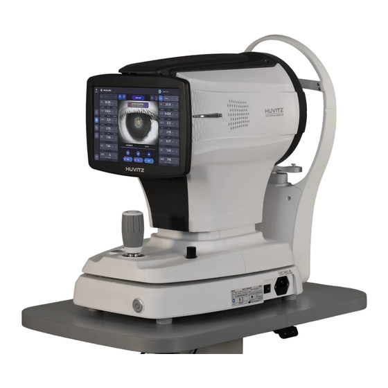
HBM-1 INTRODUCTION 3.1. System Outline The Huvitz Optical Biometer HBM-1 is a device for the biometric measurements of ocular structures. The HBM-1's functions are combined with optical biometry and corneal topography. 3.2. Intended Use 3.3. Classification • Classification of product: Class II according to Annex IX (Rule 10) of the Medical Device Directive 93/42/EEC as... -
Page 18: Patient Requirements
3.5. Patient requirements The patient who undergoes and examination by this instrument must maintain concentration for a few minutes and adhere to the following instructions; After his/her face to the chinrest, headrest. Keep the eye open Understand and follow instructions when undergoing an examination. - Contact lenses must not be worn by the patient during data acquisition If the patient does not conform to these conditions, it is not possible to take a picture correctly 3.6. -
Page 19: System Overview
HBM-1 System Overview 4.1. Configuration and Functions Front View ⑨ ⑤ ① ④ ② ③ ⑦ ⑧ ⑥ Part Name Description Display Monitor for displaying captured image and user interface icon. Chinrest button Button for moving chinrest up and down. - Page 20 Rear View ④ ① ③ ② ⑤ ⑥ ⑦ Part Name Description Headrest The part that holds the patient's head Headrest Chinrest For fixing patient’s chin. Placido disk Check the curvature of the cornea. Body Focus LED LEDs for checking patient’s eye. LAN port Port for external network (1 ports) Base...
-
Page 21: Functional Block Diagram
HBM-1 4.2. functional block diagram... -
Page 22: Main Body Screen Description
4.3. Main Body Screen Description MEASURE screen ❶ ❷ ❿ ❸ ❹ ❺ ❻ ❼ ⓫ ⓭ ❽ ⓮ ❾ ⓬ Name Function Patient information Shows the information of patient ID and name. Patient Go back to patient detail page. Go to IOL calculation page. - Page 23 HBM-1 Measurement Mode Select the measurement mode before the measurement. It informs user to check the measurement status according to the measurement process. : waiting the process. Process Check : this turn. : already measured. RESULT screen 1. Summary result (SUM) ❶...
- Page 24 2. Keratometry result (KER) ❶ ❻ ❷ ❸ ❺ ❹ ❽ ❼ ⓫ ❾ ❿...
- Page 25 HBM-1 Name Function Map: Show Topography map with various options. Map/Profile Profile: Show curvature along the meridian. Data image Show data image with the options. Eye/Map/Ring Display the image of the eye, topo map, topo rings. Axial/Tangential Select the topo map.
- Page 26 ❷ Name Function Map: Show the aberration map. Map/Graph/PSF Graph: Show the coefficients graph. PSF: Show the point spread function image. Echart : Show the E chart. Grid : Show the Grid chart. Echart/Grid/Radial/ETDRS Radial : Show the Radial chart. ETDRS : Show the ETDRS chart.
- Page 27 HBM-1 4. AL result (AL) ❸ ❹ ❶ ❷ Name Function Signal graph Show the measured signal image. Average value Show the average measured axial length value. Show each measurement axial length values. (it is the average of detail values.) Each value is evaluated by some standard.
- Page 28 5. Anterior result (ANT) ❸ ❶ ❷ Name Function Signal graph Show the measured signal image. Show the average measured Anterior values(CCT: Central Corneal Thickness, Average value ACD: Anterior Chamber Depth, LT: Lens Thickness) Show the each measurement Anterior values. Each value is evaluated by some standard.
- Page 29 HBM-1 ❺ ❻ ❼ Name Function Pupil: Show the continuous image of pupil, and check the pupil changes. Pupil/Graphs Graph: Show the Latency and Decentration graph. Captured image Show captured images during the measurement. Display options Select display options. Measurement values Show measurement data.
- Page 30 7. White to White result (WTW) ❸ ❶ ❷ ❼ ❹ ❻ ❺ Name Function WTW bar Calculate the WTW with the both bar distance. Edit Edit WTW bar states on the edit window. Values Show the White To White values. edit window Click the bar makes it active (pink color express the active state).
- Page 31 HBM-1 IOL screen 1. IOL CALCULATION ❹ ❺ ❻ ❸ ❶ ❼ ❷ ❽ ❾ ❿ ⓫ ⓬ ⓭ ⓮ ⓯ ⓰ ⓱ ⓲ Name Function Go to Result page. Result Check the measurement data detail. Go to the Measurement Data Edit pop-up window, edit data to calculate IOL Data Edit exactly.
- Page 32 It is an intrinsic constant of IOL lens model. It is necessary when calculating IOL Lens index formula. Ideal IOL Power It is an ideal IOL power that expects the target refractive value. calculation It informs 5 IOL power lists that are close to the target refractive value. result Reset Reset the calculation result.
-
Page 33: Installation Procedure
HBM-1 Installation Procedure 5.1. System installation 1. Place the main body unit on a stable table. 2. Loosen the packing lock screw under the main body. Packing lock 3. Unscrew the user lock lever on the body. Joystick User lock 4. - Page 34 Power switch Power inlet 8. If external devices are connected, turn on external devices first. 9. Turn on the main body by pressing power switch (I position) 10. Turn on the internal PC by pressing power button. Power switch Power button 11.
-
Page 35: Operation
HBM-1 Operation 6.1. Software 1. Press register patient icon ( ) and input patient information. If patient is resisted already, skip this step. 2. Select patient and check patient information is correct. 3. If you want to send patient information to a web viewer or delete patient information, select the circle next to the... - Page 36 4. When you select a patient, the screen changes. 5. Enter observation mode by pressing measure icon ( The screen of observation mode is as follow.
-
Page 37: Setup Mode
HBM-1 6.2. SETUP Mode [To choose the section to setup] - Setup mode consists of six sections: System, Patient, Measure, Connectivity, Report. You can select the section to setup from the left side. - You can navigate the setup items with the page move buttons [... - Page 38 Patient Settings Patient List Size Number of patients to be displayed per pages. Today List Today List (List of patients visited today) settings. PID Prefix The function to set the prefix of the patient ID. PID Postfix The function to set the postfix of the patient ID. PID Number Length The function to set the length of patient ID.
- Page 39 HBM-1 Connectivity Settings Network Folder Network folder path. Username Network folder user name Password Network folder user password Web Viewer Server IP Web Viewer Server IP address setting. Web Viewer Sever Port Web Viewer Server port setting. Auto Data Trans Set the function to transfer the measured data to Web Viewer automatically.
-
Page 40: Dicom Setup Mode
6.3. DICOM SETUP Mode Worklist Setting IP Address of the PC where the server program is Server IP installed. Server Port Set Port Number. Server AE Set Server AE. Client AE Set Client AE. MPPS Setting IP Address of the PC where the server program is Server IP installed. - Page 41 HBM-1 Storage Setting IP Address of the PC where the server program is Server IP installed. Server Port Set Port Number. Server AE Set Server AE. Client AE Set Client AE. General Setting Manufacturer Set the name of the manufacturer.
-
Page 42: Device Check
6.4. Device Check Measuring Model Eye. (1) Remove chinrest paper. (2) Mount Model Eye as shown below and then fix it using two paper pins. Model Eye (3) Align the center of the Model Eye with the placido disk using joystick and chinrest button. Chinrest button Joystick (4) After focusing, press the Joystick button. -
Page 43: General Operation
HBM-1 6.5. General Operation 1. Clean headrest and chinrest with a clean cotton swab or gauze. Remove a single sheet of chinrest paper if the chinrest paper is used. 2. Align left/right index mark (B) and front index mark (A) of body and base with joystick. - Page 44 Keratometer mode is on. Keratometry measurement is on. Axial Length measurement is on. CCT, ACD, LT measurement (Anterior measurement) is on. Pupillometry mode is on. If Keratometer mode is on, user can choose the Keratometry, AxialLength, CCT, ACD, LT measurement. •...
- Page 45 HBM-1 6. Align patient’s eye to eye level mark on headrest. (1) Let the patient’s chin put on the chinrest. (2) Let the patient’s forehead adhere to headrest. (3) Move up or down chinrest with the chinrest button on the body to fit the level of patient's eye to the eye level mark on the headrest.
- Page 46 (2) Move joystick little by little until orange target mark (A) appears. (3) If auto tracking is on, alignment and focus is automatically accomplished in tracking region. (4) If orange arrow (A) appears during auto tracking, it means auto tracking module go to the limit of tracking region.
- Page 47 HBM-1 If CCT, ACD, LT measurement (Anterior measurement) is on, check the real-time signal to see if the anterior signal (A) comes out well and capture. 10. Press the button on joystick to capture image. 11. If pupillometry mode is on, wait until the progress bar are full, then press the joystick to stop measurement.
-
Page 48: Maintenance
6.6. Maintenance 6.6.1. After operation Exit software and Power off. (1) Select the Patient information icon ( ) in the upper left corner of the screen. (2) Select the Previous screen icon ( ) in the upper left corner of the screen. (3) Select the Power Off icon ( ) from the bottom left corner of the screen. - Page 49 (4) Selecting POWER OFF icon ( ) shows a pop-up windo , Checking the Packing Mode will move chinrest and the body of HBM-1 to the lowest position before Power off (This is for packaging). NOTE To put the equipment in the packing box, select Packing Mode and then press OK to finish.
-
Page 50: Cleaning
Do not use the solvents such as strongly volatile substance, thinner, benzene, etc Do not use a sponge or cloth soaked in water because the water might leak into the equipment. Clean headrest rubber and chinrest with an alcohol before sending device to authorized agent or Huvitz for maintenance. -
Page 51: Replacement Of Consumables And Fuse
HBM-1 6.6.3. Replacement of consumables and fuse Replacing chinrest paper (1) Pull out two fixing pins from chinrest. (2) Put a new chinrest paper on the chinrest. (3) Insert two fixing pins into the chinrest paper hole. (4) Attach the chinrest paper to the chinrest. -
Page 52: How To Pack The Device
6.6.4. How to pack the device 1. Make sure to shut down the device with ‘Packing Mode’. Refer to “6.6.1. After operation” 2. Lift Packing locks under the bottom and turn them counterclockwise to lock the device (Important). Move the joystick to check if the device is locked firmly. Device is locked correctly if the device doesn’t move. Packing lock 3. - Page 53 HBM-1 5. Open the vinyl envelop wide. 6. Put down the device while checking the device direction. 7. Insert the foams while checking right and left side.
- Page 54 8. Close the top foam and put accessories to the right position. Accessory Foam 9. Close the inner box and seal with plastic tape. Inner box outer box 10. Put the last foam, close the outer box and seal with plastic tape..
-
Page 55: Troubleshooting Guide
HBM-1 Troubleshooting Guide Should the device function improperly, attempt to correct the problem according to the following table before contacting sales distributors. Contact a sales distributor after turning off the power when the device does not resume normal operation even after taking the following measures. -
Page 56: Specifications And Accessories
Specifications and Accessories 8.1. Standard Accessories Chinrest paper Touch pen Power cable Fuse (250V T 3.15A) Dust cover User manual Model Eye... -
Page 57: Specifications
HBM-1 8.2. Specifications Biometry Parameter Measuring range SD of Repeatability Axial length 14 – 40mm ±0.025 mm Anterior chamber depth 1.5 – 6.5mm ±0.04 mm Central corneal thickness 0.25 – 1.3mm ±0.02 mm 1.5-6.5mm(phakic) Crystalline lens thickness ±0.06 mm 0.5-3.5mm(pseudo-phakic) White-to-white distance 7 –... -
Page 58: Exploded Diagram
Exploded Diagram 9.1 COVER ASSY ① ⑦ ③ ⑨ ⑧ ⑤ ⑥ ④ ② CODE PART NAME Quantity Disassembly sequence first 2000A001451 V1_TOP-COVER second 2000A001452 V1_FRONT-COVER third 2000MPR0121 V1_SIDE-COVER-L forth 2000MPR0122 V1_SIDE-COVER-R fifth 2000A001448 V1_M-CASE-B sixth 2000A001449 V1_M-CASE V1MASSY031 V1_PLACIDO-ASSY V1MASSY055 V1_LCD-ASSY V1MASSY012... -
Page 59: Base Assy
HBM-1 9.2 BASE ASSY ① ⑫ ⑪ ④ ③ ⑤ ② ⑥ ⑦ ⑧ ⑩ ⑨ CODE PART NAME Quantity REMARK 1330MP00150 V1_BTM-PLATE 75010010023 SMPS 1330MP00153 V1_SMPS-BRK V1EPCB0002 USB_ETHERNET PCB ASSY 79050010004 AC-INLET-FILTER 7600SOFR9D2 POWER-SWITCH 1200A000512 V1_HEADREST-CNT 1200A00A201 PACKING-LOCK-KNOB W2EHAR0059... -
Page 60: Lcd Assy
9.3 LCD ASSY ① ⑨ ⑧ ② ⑩ ⑦ ⑥ ⑤ ④ ③ CODE PART NAME Quantity REMARK V1MASSY057 V1_LCD-FRONT-CASE-ASSY 72050010015 HBM-LCD 2000A001453 V1_LCD-BACK-CASE 1330MP00169 V1_LCD-FRAME 79990010021 TOUCH-IF-BOARD 3099A000140 V1_STAY 1330MP00167 V1_HINGE-BRK 1330MP00168 V1_HINGE-SPC 3099A000141 V1_TORQUE-HINGE-L-ASSY 3099A000142 V1_TORQUE-HINGE-R-ASSY... -
Page 61: Pc Assy
HBM-1 9.4 PC ASSY ② ③ ① ④ ⑤ ⑥ ⑧ ⑦ CODE PART NAME Quantity REMARK 1330MP00163 V1_PC-COVER W2EHAR0072 HARNESS(MB TO OPTICAL FAN) 79990010011 HDD(2.5Inch 1TB) 1330MP00164 V1_2_5-HDD-BRK 79990010106 1330MP00162 V1_PC-CASE-BTM 1330MP00161 V1_PC-FIX-PLATE V1EPCB0003 PCB ASSY(HBM-PC-IF) -
Page 62: Headrest Assy
9.5 HEADREST ASSY ③ ⑧ ⑤ ② ⑥ ④ ⑦ ① CODE PART NAME Quantity REMARK 2000A001446 V1_HR-COVER 1200MS00036 V1_HR-BODY 2090A000034 V1_HR-HEADREST W2EPCB0018 PCB ASSY(W2_CRPI-010) 2000A001447 V1_HR-CHINREST 1130MS00001 V1_HR-NECK W2EHAR0061 HARNESS(BIF(CN11) TO CR MOT) CHIN REST MOTOR W2EHAR0062 HARNESS(BIF(CN9) TO CR PI) -
Page 63: Replacement
HBM-1 Replacement 10.1 SMPS 1) Check the power switch on the bottom right of base is off. (O position) 2) Disconnect the power cable from the power inlet. Power switch Power inlet 3) Align left/right index mark (B) and front index mark (A) of body and base with joystick. - Page 64 5) Lean the device as shown below with caution. 6) Unscrew four bolts in the circle as shown below. (red: wrench bolt, blue: cross recess bolt) Remove the ‘V1_BTM-PLATE’. V1_BTM-PLATE...
- Page 65 HBM-1 7) Unlock four bolts in the circle as shown below. 8) Uncouple harness connector to separate SMPS. 9) Change the SMPS with new one. 10) Reassemble in reverse order. Be careful when insert the SMPS ASSY into the main body.
-
Page 66: Emc Information
Voltage fluctuations/flicker IEC 61000-3-3 Complies • Electromagnetic waves tolerance HBM-1 is to be used in the below designated electromagnetic wave environment. HBM-1 customer and user need to guarantee that the HBM-1 will be used in this type of environment. IEC 60601... - Page 67 HBM-1 • Electromagnetic waves tolerance HBM-1 is to be used in the below mentioned electromagnetic wave environment. HBM-1 purchaser or user needs to confirm whether HBM-1 is sued at this environment. IEC 60601 Tolerance test Appropriateness level test conditions 3 Vrms...
-
Page 68: Service Information
Parts below are consumable in their characteristics, or the quality of them shall degraded after the long time use. User should not replace them by him or herself. Please contact to Huvitz`s agent for the replacement if these parts are consumed enough or degraded by the longtime use. - Page 69 HBM-1 ■ U.S.A Representative COBURN TECHNOLOGIES 55 Gerber road, South Windsor, Connecticut, 06074, United states Tel: +1-860-648-4906 ■ Brazil Representative VR Medical R. BATATAES 391, CEP 01423, SÃ O PAULO Tel: +55-11-3889-0875 ■ Australia Representative OPTICARE 118 Adderley St, Auburn NSW 2144...
-
Page 70: Software License Agreements
Documentation are protected by copyright laws and international copyright treaties, as well as other intellectual property laws and treaties. 3. SOFTWARE VERSION The Software and the Documentation may be updated or modified at HUVITZ's own discretion from time to time without any prior notice. - Page 71 7. FORCE MAJEURE In no event HUVITZ will be liable to you for any delay or failure in the performance of its obligations under this Agreement if and to the extent such delay or failure in performance arise from any cause or causes beyond the reasonable control of HUVITZ, including, but not limited to, fire, explosion, flood, earthquake, war, rebellion or riots.
- Page 72 Sections of this Agreement will remain in full force and effect. 14. NO WAIVER The delay, omission or failure of HUVITZ to enforce any right or remedy in this Agreement will not be construed to be a waiver of such right or remedy of HUVITZ.
Need help?
Do you have a question about the HBM-1 and is the answer not in the manual?
Questions and answers