Table of Contents
Advertisement
Advertisement
Table of Contents

Related Manuals for Huvitz HLM-1


Summary of Contents for Huvitz HLM-1
- Page 1 Auto-Lensmeter HLM-1 User Manual...
-
Page 2: Content
30cm) We believe that the contents in this User Manual were carefully examined and overall precise. However, Huvitz will not be held responsible for any potential errors or omissions caused from the use of information in this User Manual. -
Page 3: Table Of Contents
HLM-1 CONTENT 1. INTRODUCTION ......................6 1.1. E .................... 6 QUIPMENT UMMARY 1.2. C ....................6 LASSIFICATIONS 2. SAFETY INFORMATION....................7 2.1. I ....................... 7 NTRODUCTION 2.2. S ....................8 AFETY YMBOLS 2.3. E ..................11 NVIRONMENTAL YMBOL 2.4. S .................... - Page 4 7.1. B ........24 UTTON OMPOSITION CCORDING TO EASURING 7.2. U ....................25 SE OF UTTONS 8. SCREEN COMPOSITION ................... 28 8.1. M ..................28 EASUREMENT CREEN 8.1.1. Specifics....................... 29 8.2. P ................. 30 ROGRESSIVE CREEN 8.2.1. Specifics....................... 31 8.3. A .....................
- Page 5 HLM-1 9.4.2. Measurement on Progressive Screen ............58 9.5. C ..................... 60 ONTACT 9.6. M ................. 61 EASURING OINT ARKING 9.6.1. Without Astigmatism ..................61 9.6.2. With Astigmatism ..................62 9.7 P ........................62 RISM 9.8 P (HRK ) ....................62...
-
Page 6: Introduction
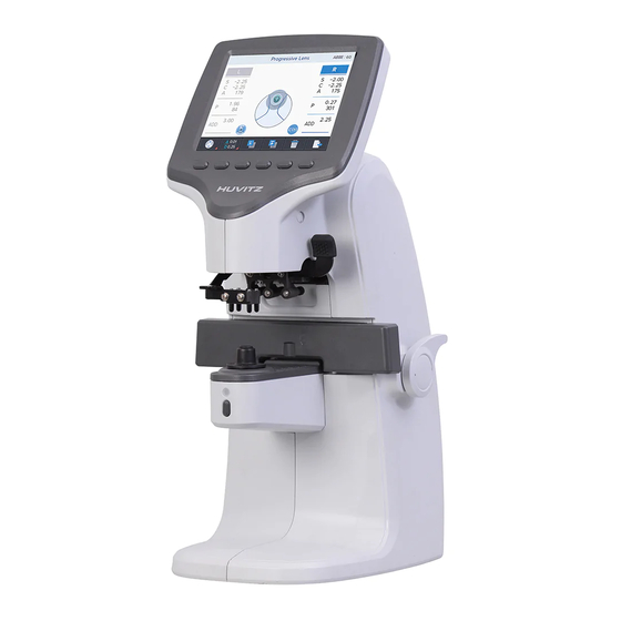
Introduction 1.1. Equipment Summary Auto Lensmeter HLM-1 is a machine to generate Sph, Cyl and Axis information of lens by measuring refraction of the lens. Auto Lensmeter HLM-1 can measure both unprocessed single lens and eyeglass lens with frames. Bi-focal lens or progressive lens can be examined using this equipment as well. -
Page 7: Safety Information
HLM-1 Safety Information 2.1. Introduction Safety is primary responsibility for all people. Safe use of this equipment is a concern for installer, user, operator and administrator. Any person shall be familiarized with the contents of this User Manual before installing, using, cleaning, repairing or adjusting this equipment and its supplementary items. -
Page 8: Safety Symbols
CAUTION “Caution” signifies an association with disaster that can cause minor injury or property damage if not careful. INFORMATION “Information” is to generate information needed on each page that is appropriate at the phase. 2.2. Safety Symbols The International Electrotechnical Commission (IEC) has established a set of signs on medical electronic devices by classifying caution or association of electronic danger. - Page 9 HLM-1 It signifies a safe earthing point where safe earth is fixated on sash. For safety, connect protective earth to conductive part of class I apparatus. Alternating Current. Direct Current. Serial Number Humidity Limitation Atmospheric Pressure Limitation This side up...
- Page 10 Do not use hand hooks Keep DRY Stacking Limit by Number Keep away from sunlight Huvitz Symbol • Other Sign External series connection port. User can transmit saved data to other equipment of Huvitz or other devices such as a PC.
-
Page 11: Environmental Symbol
HLM-1 2.3. Environmental Symbol Avoid following environments for operation or storage of this equipment. A place where the equipment can be exposed to water. Do not operate the equipment with wet hand. A place where the equipment can be exposed to direct sunlight. - Page 12 Watch out for dust, especially metal pieces from entering the equipment. Do not disassemble the product. Huvitz will not be held responsible for any negligence regarding such action. Do not connect the AC power adapter before all parts are fully assembled.
-
Page 13: Safety Precaution
HLM-1 NOTE • Avoid installing the device on a place where it is exposed direct sunlight near illumination. In particular, ensure that the device is not illuminated by a spot light from the upper front. • Before putting the device on a light-reflecting surface such as a glass showcase or a shiny table, put a cloth on it. - Page 14 Repair of this equipment shall be handled by service personnel at Huvitz or a person with equivalent certification. Customer’s care over this equipment shall be done only according to the User Manual and Service Instruction. Any other maintenance shall be done by service personnel at Huvitz or a person with equivalent certification.
- Page 15 HLM-1 Do not block the air grafting or holes. Immediately turn off the power and remove plug when smoke, flame, unusual noise or smell is detected from the equipment. This equipment generates, uses and can radiate radio frequency energy and, if not installed and used in accordance with the instructions, may cause harmful interference to other devices in the vicinity.
-
Page 16: Feature
CAUTION For use of equipment in rated voltage less than 125Vac, minimum 6A,Type SJT or SVT , 18/3AWG,10A, max 3.0m long : One end with Hospital Grade Type, NEMA 5-15P Other end with appliance coupler. For use of equipment in rated voltage less than 250Vac, minimum 6A, Type SJT or SVT, 18/3AWG, 10A, max 3.0m long : One end terminated with blade attachment plug(HAR) Type, NEMA 6-15P. -
Page 17: Instructions For Use
HLM-1 Instructions for Use Do not hit or drop the equipment. Strong pressure might damage the equipment. Strong pressure can affect the function of the equipment. Thus, always handle with care. Install the equipment in a stable place without vibration to maintain normal condition. -
Page 18: Composition
Composition 5.1. Main Parts Front LCD Screen Button Marking Lever Lens Table Lever Lens Holder Lever Lens Cap Lens Table MEM Button (Save Button) - Page 19 HLM-1 Back Power Switch Bottom RS-232 Connector Power Connector...
-
Page 20: Supplementary Articles
5.2. Supplementary Articles ① Fuse (250V T3.15AL) : (2) ② User Manual: Operation guide for users ③ Power Cable (180cm) : (1) ④ Dust Preventive Cap: a cap to prevent dust from entering : (1) ⑤ Contact lens tweezer: a tool to pick up contact lenses ⑥... -
Page 21: Equipment Installation And Preparation
HLM-1 Equipment Installation and Preparation 6.1. Parts Inspection 1. Inspect supplementary articles. Open the box and make sure all articles are there (dust cover, User Manual and etc.). 2. Remove protection tapes. Remove protection tapes on lens holder, lens cap, marking lever. - Page 22 Screen showing an initialize error (1) Screen showing an initialize error (2)
-
Page 23: Screen Saver
HLM-1 1. Turn on the equipment, and make sure there are not any objects on the lens cap. 2. If a message that says, “Initialize error” is displayed as shown in (Picture : Screen showing an initialize error (1)), check to see there are any objects placed on the lens cap or pinhole, and remove if there is any. -
Page 24: Button Composition
Button Composition 7.1. Button Composition According to Measuring Mode Screen change according to button selection • General Lens Measurement Screen Buttons • Progressive Lens Measurement Screen Buttons • Auto Detect Mode(General/ Progressive Lens) Screen Buttons • Contact Lens Measurement Screen Buttons... -
Page 25: Use Of Buttons
HLM-1 7.2. Use of Buttons General Lens Screen to measure general lens (including lens for sunglasses) Progressive Lens Screen to measure progressive multifocal lens Auto Detect Mode Determine the type of lens (general or progressive) currently being measured, and then convert to progressive lens measurement screen automatically if the lens is a progressive lens. - Page 26 STEP Display the Prism(∆), Diopter(D) step. (0.25, 0.12, 0.06, 0.01) Change the Diopter Step (popup) You can change the diopter(S, C, ADD) value (unit: 0.25, 0.12, 0.06, 0.01) without entering the user setup screen, immediately. Change the Diopter Step (popup) You can change the prism(S, C, ADD) value (unit: 0.25, 0.12, 0.06, 0.01) without entering the user setup screen, immediately.
- Page 27 HLM-1 DATA TRANS Transmit the stored data. and deletes the data. START / STOP Start/stop measuring current data on contact lens measurement screen and save the average. MEM (Save) Button Save current measurement.
-
Page 28: Screen Composition
Screen Composition 8.1. Measurement Screen Basic screen composition 1. Current Measurement Mode 2. ABBE Value 3. Measurement Data 6. Prism Display 8. Measurement 4. Measurement Status Lens Activation 5. Measurement Position 7. Cylinder Sign... -
Page 29: Specifics
HLM-1 8.1.1. Specifics 1. Current Measurement Mode Indicates the type of lens (general, progressive multifocal, Auto detect mode, contact) currently being measured. 2. ABBE Value Current ABBE setting is marked. 3. Measurement Data Measurement data is marked. Each article signifies the below. -
Page 30: Progressive Lens Screen
6. Prism Display Display the prism zone on screen. 7. Cylinder Sign Current cylinder sign is marked as ±, + or - . 8. Measurement Lens Activation Indicates the type of lens (single lens, left or right) currently being measured. 8.2. -
Page 31: Specifics
HLM-1 8.2.1. Specifics 1. Distance viewing zone Measurement Position Position of current measurement is indicated while searching for the center of distance viewing zone. 2. Near viewing zone Measurement Position Position of current measurement is indicated while searching for the center of near viewing zone. -
Page 32: Specifics
8.3.1. Specifics Automatically determine the type of lens (general or progressive) currently being measured, and then convert to progressive lens measurement screen automatically if the lens is a progressive lens. 8.4. Contact Lens Screen Contact lens screen composition 1. Start/Finish Saving 2. -
Page 33: Specifics
HLM-1 8.4.1. Specifics 1. Start/Finish Saving Start recording results of consecutive measurement. Start saving button will change its shape to finish saving button after pressing it. (Finish: Average of all measurement results are calculated and saved.) 2. Reliability Graph It will show the sizes of recognized dots proportionally. If any one of the dots is lower than the baseline, the measurement value at the moment will not be considered. - Page 34 1. START MODE : Select the initial measurement mode. - Normal : Select the initial measurement mode to normal lens measurement mode. - Prog : Select the initial measurement mode to progressive lens measurement mode. - Auto : Select the initial measurement mode to auto detect mode. - Contact : Select the initial measurement mode to contact lens measurement mode.
- Page 35 HLM-1 - Off : Disable the function. - On : Enable the function. (Both distance viewing zone and near viewing zone data will be saved.) 6. WAVE LENGTH - e-Line : Mark refraction based on e-Line. - d-Line : Mark refraction based on d-Line.
- Page 36 Set up screen composition – ABBE(ABBE:Edit) 2. CONTACT REC Choose to start/stop contact lens measurement during the duration user has set (unit: second) on contact lens measurement mode. - Manual: User will start measurement by pressing [ : START ] button, and stop by pressing [ : STOP ] button.
- Page 37 HLM-1 Set up screen composition – Measurement Duration (CONTACT REC:Edit) 3. STEP S/C/ADD Set S, C and ADD value indication units. - 0.25 : Set S, C and ADD value indication unit to 0.25. - 0.12 : Set S, C and ADD value indication unit to 0.12.
- Page 38 5. CYLINDER MODE Set how to indicate cylinder sign. - Mix : Mark cylinder sign as (+) when average power is (+). Mark cylinder sign as (-) when average power is (-). - + : Mark cylinder sign as (+) at all times. - - : Mark cylinder sign as (-) at all times.
- Page 39 HLM-1 1. PRISM DIRECTION Set direction of cross mark movement on measurement screen. - Comfort (Comfortable) : Set cross mark to move in the direction of lens movement for user convenience. (Prism Display: Prism angle and cross mark position on screen might not accord during PB setting.)
- Page 40 - 9600 : Set communication speed to 9600. - 57600 : Set communication speed to 57600. - 115200 : Set communication speed to 115200. 6. COMM PRINT Set to print out by connecting with HRK series. - Off : Disable the function. - On : Enable the function.
- Page 41 HLM-1 2. COLOR SETTING Adjust color temperature of LCD display. - Edit : COOL ~ WARM. 3. LCD BRIGHTNESS Adjust brightness of LCD display. - Edit : 10% ~ 100%.
- Page 42 4. DEFAULT SETUP Initialize the user setup data to default value. - Reset : Do you really want to reset?
-
Page 43: Measurement
HLM-1 Measurement 9.1. General Lens How to measure a general lens Reset measurement status by pressing ‘CLEAR’ button ( ① Set measurement lens on the top right corner of the screen to ‘S’. (However, ‘R’ will be displayed if ‘SINGLE LENS’ function is set to ‘Off’ on User Set Up screen. - Page 44 Focus adjustment [ OFF center ] [ ALIGNMENT OK ] [ MARKING OK ] ④ For a lens with astigmatism power, rotate the lens so the astigmatism angle is 180°. INFORMATION There is no need to adjust astigmatism angle to 180° when the lens is without astigmatism power or when there is no need to mark astigmatism focus and cylinder axis.
- Page 45 HLM-1 Press ‘MEM’ button to save the measurement. Data will be fixated after saving ⑤ the data. Pressing ‘MEM’ button once again will save and fixate modified measurement. INFORMATION ‘AUTO MSR NORMAL’ function is to save measurement automatically 1 second after ‘MARKING OK’...
- Page 46 Measurement status display [ No lens has been placed ] [ A lens has been placed ] INFORMATION A drawing of the lens cap without a lens will be displayed on the bottom left corner of the screen when a lens is not placed. If a drawing of the lens cap with a lens is displayed even when there is not a lens placed on the actual lens cap, restart the equipment to operate automated set up to readjust zero point.
-
Page 47: Eyeglass Lens
HLM-1 9.2. Eyeglass Lens Eyeglass lens measurement Press ‘S->R’ button ( ① ) to enter eyeglass lens measurement environment. ‘L’ and ‘R’ will be displayed on the top of the screen. CAUTION Activated data result screen indicates the lens currently being measured, and inactivated screen indicates the opposite side lens. - Page 48 ④ Pull up the lens holder and place the left lens. CAUTION When ‘SINGLE LENS’ function is On, press ‘S->R’ button ( ) to select a lens to measure. Adjust focus until ‘MARKING OK’ is displayed. Press ‘MEM’ button to save the ⑤...
-
Page 49: Progressive Multifocal Lens
HLM-1 9.3. Progressive Multifocal Lens 9.3.1. Structure of Progressive Multifocal Lens Structure of single progressive lens Lens Table Near Center Far Center INFORMATION Horizontal line of a lens shall be placed parallel to the lens table. INFORMATION As shown on the picture above, distance viewing zone of the lens shall be... - Page 50 Structure of framed progressive lens 2~3mm 2~3mm [ Framed Lens ] INFORMATION Sizes of progressive multifocal lenses vary according to manufacturers. INFORMATION Some of the old type progressive lenses do not comply with 2~3mm standard toward the frame center. INFORMATION Do not pick up the lens during measurement.
-
Page 51: Judgment Of Progressive Multifocal Lens
HLM-1 INFORMATION If lensmeter is operated with sensitive measuring when put on the progressive lens using auto measurement, The best way of progressive measurement is that putting on the lens in ) with using lens holder. 9.3.2. Judgment of Progressive Multifocal Lens ①... - Page 52 Progressive band for autonomous judgment The icon on the bottom left of the screen will change as the below (‘no lens’ → ③ ‘progressive lens’). Then, the screen will automatically convert to progressive lens measurement screen. Change of status icon INFORMATION When progressive power is smaller than 1D, automated judgment might not work.
-
Page 53: Distance Viewing Zone Measurement
HLM-1 INFORMATION If the lens was not placed properly on ➁, it will be displayed as general lens on ➂. In such cases, move the lens to progressive band, and it will be converted to progressive lens measurement screen. 9.3.3. Distance Viewing Zone Measurement ①... -
Page 54: Near Viewing Zone Measurement
INFORMATION Both single lens and eyeglass lens shall be placed parallel to the lens table. 9.3.4. Near Viewing Zone Measurement ① Move the lens to near viewing zone. For an eyeglass lens with erased marker, push until the leg on the lens holder reaches the bottom frame of the eyeglass. INFORMATION For an eyeglass lens, it is advisable to pull the lens using the lens table while maintaining parallel to the lens table. - Page 55 HLM-1 Small eyeglass lens [Case 1] [Case 2] INFORMATION (Case 1) For eyeglass lens with small frame, pull up the lens holder and pull a little more to find the near viewing zone center since the near viewing zone center is nearby the bottom frame. (Picture : Small eyeglass lens)
-
Page 56: Troubleshoot During Progressive Lens Measurement (Auto Detect Mode)
9.3.5. Troubleshoot during Progressive Lens Measurement (Auto Detect Mode) ① When a progressive lens has failed to be auto-determined. Cause 1 The lens might not be placed on progressive band. General lens icon is displayed on the bottom left corner of the screen. - Page 57 HLM-1 If progressive area is expanded into distance viewing zone, it is Cause 1 difficult to find the distance viewing zone. Place the cross mark as close as to distance viewing zone target Countermeasure center, and press ‘MEM’ button. If distance viewing zone is near the upper frame, it is difficult to Cause 2 find.
-
Page 58: General Multifocal Lens
measurement. It can be because distance viewing zone center was measured Cause 1 incorrectly. Countermeasure Measure the distance viewing zone center again. 9.4. General Multifocal Lens 9.4.1. Measurement on General Screen Place a lens on the first focal center, and press ‘MEM’ button. ①... - Page 59 HLM-1 ② Move the lens to the first focal center. Progressive measurement will be conducted automatically. ③ Move the lens to the second focal center, and progressive value will be measured automatically. INFORMATION If auto-measurement does not work on each stage, or if you want to measure...
-
Page 60: Contact Lens
9.5. Contact Lens ① Press Measurement Mode button ( ), and select Contact Lens Measurement Mode ( ② Remove moist using a clean lens towel. Soft contact lens can tear up easily, and remove moist with light touches before waiting 5 seconds for lens to recover its curved shape. -
Page 61: Measuring Point Marking
HLM-1 9.6. Measuring Point Marking 9.6.1. Without Astigmatism ① Place a lens on the lens cap, and move the lens until ‘MARKING OK’ is displayed. ② Tilt the marking lever to reach 90° to horizontal. ③ Pull down the marking lever to mark. -
Page 62: With Astigmatism
9.6.2. With Astigmatism Place a lens on the lens cap, and move until ‘MARKING OK’ is displayed. ① Adjust lens to the angle on the prescription while maintaining ‘MARKING OK’. ② ③ Tilt the marking lever to 90 to horizontal and mark. 9.7. -
Page 63: Print (Hrk Print)
Connectable devices: HRK-1, HRK-9000A, HRK-8000A, HRK-7000/7000A [ Sample ] Connecting procedures ① Connect the HRK to the interface connector of the HLM-1 with the interface cable. * Interface cable (optional) CAUTION Be sure to turn off each device before connecting the interface cable, etc. - Page 64 Setup procedures Set the following parameters on the HLM-1 and HRK. ① Set the following parameters related to communications on the HLM-1. - RS-232C (COM): LMTORK, BPS: 115200, COMM PRINT: On ② Set the following parameters on the HRK. - HLM PRINT: On...
-
Page 65: Self-Diagnosis And Maintenance/Repair
HLM-1 Self-diagnosis and maintenance/repair 10.1. Prior to calling a serviceman Warning appears on the screen when there is a problem or when this device malfunctions. Take the following measures in case of the following. Contact a sales distributor after turning off the power when the device does not resume normal operation even after taking the following measures. -
Page 66: Fuse Replacement
② Message during measurement Message Root causes Measures Indicates when the signal Clean lens Measuring Error of the measurement is pinholes, and be measured poor. again. ③ Message when data transmitting Message Root causes Measures Wait until the data transfer is Data Transmitting…... -
Page 67: Storage
Place the new fuse box in the fuse location. . INFORMATION Auto Lensmeter HLM-1 uses a 250V, T3.15AL fuse. 10.3. Storage While not use, cover up the device with the dust cover as shown in (Picture : How to store while not use) for storage. -
Page 68: Disposal
For long-term storage 10.4. Disposal NOTE Please obey the law relating to the equipment and its part to discard the equipment or its part(s). For example, discarding a lithium battery is a threat to the environment. When discarding packaged part(s), disassemble the part(s) and obey the law and recycling regulations. -
Page 69: Various Messages
HLM-1 10.5. Various Messages Message box shows information when you are measuring or this instrument is out of order. Measuring Error screen Measuring Error It is displayed when there is no signal. It is displayed when there is out of range signal. -
Page 70: How To Clean Pinhole
Data Transmitting… screen Data Transmitting… It shows a state while the data transmission. (If you set the setup mode RS-232C (COM) -> LMTORK) 10.6. How to Clean Pinhole If the S, C and A values are not 0 when the equipment starts up, clean the pinhole. Remove the lens cap and wipe using a clean lens towel as sown in (Picture : How to clean the pinhole). - Page 71 Do not use liquid such as alcohol or acetone as it can dissolve the adhesive on the pinhole. If the S, C and A values are not 0 after cleaning the pinhole, please inquire with an authorized dealer or Huvitz Service Department.
-
Page 72: Major Specification
Major Specification • Measurement Range Spherical Power 0D ~ ±25D (0.25/0.12/0.06/0.01) Cylinder Power 0D ~ ±10.00D (0.25/0.12/0.06/0.01) Cylinder Axis ~ 180 step) Progressive Power 0 ~ 10D (0.25/0.12/0.06/0.01) Prism 0 ~ 20 (0.25/0.12/0.06/0.01) • Measurement Mode Cylinder ±, + , - Prism Rectangular / Pole / Displacement LED wave... -
Page 73: Emc Information
Manufacturer announcement – electromagnetic waves tolerance • Electromagnetic waves tolerance HLM-1 is to be used in the below designated electromagnetic wave environment. HLM-1 customer and user need to guarantee that the HLM-1 will be used in this type of environment. IEC 60601... - Page 74 Other UT is the a.c. power voltage for before approving the test level. • Electromagnetic waves tolerance HLM-1 is to be used in the below mentioned electromagnetic wave environment. HLM-1 purchaser or user needs to confirm whether HLM-1 is sued at this environment. IEC 60601...
-
Page 75: Service Information
Date of Purchase Name of Seller Seller Address Seller Phone Model Number Serial Number If you have trouble contacting the place of purchase, contact the service department at Huvitz directly using the addresses and phone numbers below. - Page 76 How to Contact HUVITZ Co., Ltd 38, Burim-ro 170beon-gil, Dongan-gu, Anyang-si, Gyeonggi-do, 14055, Republic of Korea Tel: 031-428-9100 (Primary) Fax: 031-477-9022(C/S) http://www.huvitz.com e-mail: svc@huvitz.com EU Representative Medical Device Safety Service GmbH (MDSS) Schiffgraben 41, 30175 Hannover, Germany Tel: +49-511-62628630 Fax: +49-511-62628633...
Need help?
Do you have a question about the HLM-1 and is the answer not in the manual?
Questions and answers