
Related Manuals for Bizerba VSI330 F


Summary of Contents for Bizerba VSI330 F
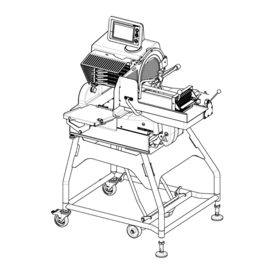
- Page 1 Slicer VSI330 F / VSI330 F W VSI330 F T / VSI330 F TW Instruction manual NSF 38065447002 en-US...
- Page 2 Alle Rechte vorbehalten All rights reserved Tous droits réservés Reservados todos los derechos Tutti i diritti riservati Bizerba SE & Co. KG, 72336 Balingen Postfach 10 01 64 72301 Balingen, Germany Telephone (+49 7433) 12-0, Fax (+49 7433) 12-2696 E-mail: marketing@bizerba.com Internet: www.bizerba.com...
-
Page 3: Table Of Contents
Instruction manual NSF VSI / VSI W / VSI T / VSI Table of Contents Table of Contents About these instructions ................... 5 Safe-keeping.................... 5 Target group .................... 5 Symbols used .................... 5 Warnings...................... 6 About this machine .................... 7 Intended use .................... - Page 4 Instruction manual NSF VSI / VSI W / VSI T / VSI Table of Contents Operation........................ 46 Log in operator..................... 46 Main page (individually configured operator page) ........ 46 Navigation between the pages.............. 47 Parameter page ................... 48 Tile manager .................... 48 Search mask ....................
-
Page 5: About These Instructions
The minimum age of the operating personnel by German law is 14. Other age limits may ap- ply according to the corresponding national regulations. Therefore the operating company must check the legislation at the place of machine installation. Installation, maintenance and repair works must be performed by Bizerba authorized special- ists only. Symbols used Various symbols are used in these instructions. -
Page 6: Warnings
Instruction manual NSF VSI / VSI W / VSI T / VSI About these instructions Information Additional information for better understanding. Warnings Warnings are divided into danger levels by the signal word above the warning symbol. Structure of warnings and meaning of signal words are described in these instructions as fol- lows. -
Page 7: About This Machine
Note: If cheese is the main product being sliced, we recommend using a special cheese blade. Slicing of other materials requires prior written approval by Bizerba product management. Non-permitted product The following may not be sliced due to risk of injury and damage: –... -
Page 8: Machine Description
VSI330 F W = machine with depositing table, scale (W), 400 mm or 600 mm carriage VSI330 F T = machine with conveyor belt (T), 400 mm or 600 mm carriage VSI330 F TW = machine with conveyor belt (T), scale (W), 400 mm or 600 mm carriage All versions are available with a mobile bench. - Page 9 Instruction manual NSF VSI / VSI W / VSI T / VSI About this machine The carriage plate is made of stainless steel plate. All components getting in direct contact with food and materials used in the working area comply with the food hygiene regulations. For bearings in visual range, food-grade lubricants are used.
-
Page 10: Names Of Components Vsi W
Instruction manual NSF VSI / VSI W / VSI T / VSI About this machine 2.2.1 Names of components VSI W Fig. 1: Names of components VSI W 10 / 101 38065447002 en-US... - Page 11 Instruction manual NSF VSI / VSI W / VSI T / VSI About this machine The machine is available in different versions. The figure shows an example: Blade guard ring Blade Blade cover Product holder complete with remnant holder Product fixation device, horizontal Feeding carriage Carriage Identification plate...
-
Page 12: Names Of Components Vsi T
Instruction manual NSF VSI / VSI W / VSI T / VSI About this machine 2.2.2 Names of components VSI T Fig. 2: Names of components VSI T 12 / 101 38065447002 en-US... - Page 13 Instruction manual NSF VSI / VSI W / VSI T / VSI About this machine The machine is available in different versions. The figure shows an example: Blade guard ring Blade Blade cover Product fixation device, vertical Product holder complete with remnant holder Carriage Carriage guide Display and operating unit with ON/OFF switch at the bottom of the machine housing...
-
Page 14: Names Of Components Vsi Tw
Instruction manual NSF VSI / VSI W / VSI T / VSI About this machine 2.2.3 Names of components VSI TW Fig. 3: Names of components VSI TW 14 / 101 38065447002 en-US... -
Page 15: Accessories
Display and operating unit with ON/OFF switch at the bottom of the machine housing (optionally on top) 2.2.4 Accessories Only use the original Bizerba spare parts and accessories in order to en- sure safe and trouble-free operations. standard – Instruction manual –... -
Page 16: Warranty
To ensure that the machine is recycled environmentally friendly, return the machine to the manufacturer or the dealer after intended use has expired. Naturally, Bizerba and its dealers will take back free of charge old machines no longer in op- eration. -
Page 17: Safety Instructions
– Protective devices may not be removed, modified or bypassed. DANGER Open the electrical installation area! danger to life due to electric current – The electrical installation area may only be opened by Bizerba Ser- vice. – Pull power plug before moving the machine. WARNING Unauthorized persons! Serious injuries to fingers and hands and damage to health. -
Page 18: Safety Instructions For Transport And Installation
Destruction of electric components, fire hazard. – Do not connect the machine to the power supply if the power supply data does not correspond to the machine's connection values. Mains data must be identical. – Inform Bizerba Customer Service. 18 / 101 38065447002 en-US... -
Page 19: Safety Instructions During Operation, Slicing
Instruction manual NSF VSI / VSI W / VSI T / VSI Safety instructions Safety instructions during operation, slicing WARNING Rotating blade! Cut injuries – Do not allow yourself to become distracted. Concentrate on the task in hand and avoid time pressure. –... -
Page 20: Protective And Safety Devices
– Check if the machine is complete before it is re-started. – Check if components are positioned correctly and firmly. – Only use original Bizerba spare parts and accessories. Protective and safety devices – Blade guard ring, stationary, cannot be removed –... -
Page 21: System Design Related Residual Hazards
Instruction manual NSF VSI / VSI W / VSI T / VSI Safety instructions System design related residual hazards Fig. 4: VSI W 38065447002 en-US 21 / 101... - Page 22 Instruction manual NSF VSI / VSI W / VSI T / VSI Safety instructions Fig. 5: VSI TW 22 / 101 38065447002 en-US...
-
Page 23: Installation
Instruction manual NSF VSI / VSI W / VSI T / VSI Installation Installation Unpacking instructions When transporting the machine, shoes with toe caps must be worn and suitable lifting devices must be used. For moving the machine at least four people are required. Weight of ma- chine is higher than 100 kg. -
Page 24: Transport And Storage
4.3.1 Installation requirements Safe operation of the slicer within the standards and guidelines is ensured on the Bizerba stand. Stand and slicer bear a CE mark (or UL/cUL mark within the area of application). The integrated scale can only be reliably used with the Bizerba stand. -
Page 25: Position On Stand
500 mm if machine is installed on a stand. 4.3.2 Position on stand Installation as well as instruction on how to operate the stand are initially provided by the Bizerba service. DANGER Tipping hazard when improperly installed! This may result in serious injuries and damage to property. - Page 26 Instruction manual NSF VSI / VSI W / VSI T / VSI Installation Put weight on mobile stand's feet by lift- ing the wheels. Lock casters. CAUTION! Crushing hazard when lower- ing the wheels. Use bracket to lift and lower wheels. Fig. 8: VSI on mobile stand 26 / 101 38065447002 en-US...
-
Page 27: Electrical Connection
Instruction manual NSF VSI / VSI W / VSI T / VSI Installation 4.3.3 Electrical connection Information on identification plate Bizerba logo BIZERBA Machine type Model VSI330 F / VSI330 F W / VSI330 F T / VSI330 F TW Machine description Slicer Machine number Production code X-.. Protection type... -
Page 28: Start-Up
With severely contaminated mains supplies (e.g. when "thyristor-controlled systems" are used) measures must be taken on-site to suppress interferences, e.g.: – A separate supply line must be planned for Bizerba machines – In problem cases, install capacitive decoupled isolating transformers or other suppressors... -
Page 29: Decommissioning
Instruction manual NSF VSI / VSI W / VSI T / VSI Installation Decommissioning If the machine is not going to be used for a longer period of time: Switch off machine. Pull out power plug. Clean machine as per cleaning instructions. 38065447002 en-US 29 / 101... -
Page 30: Machine And Operating Elements
Instruction manual NSF VSI / VSI W / VSI T / VSI Machine and operating elements Machine and operating elements Display and operating unit The slicers are operated via a touch screen. Fig. 11: Display and operating unit <ON switch> (green) LED (white) lights up when machine is switched on <OFF switch>... - Page 31 Instruction manual NSF VSI / VSI W / VSI T / VSI Machine and operating elements Parameter After pressing the icon, the operator page with all parameters (parameter page) comes up on the touch screen. Sharpening After pressing the icon, notes on the further operating proce- dure appear on the touch screen.
-
Page 32: Parameter Symbols
Instruction manual NSF VSI / VSI W / VSI T / VSI Machine and operating elements PLU menu: Save PLU Save PLU as Delete PLU Search PLU Load / open PLU Enter / Next Confirm / Accept Cancel / Refuse Empty all input fields of the search mask 5.2.1 Parameter symbols... - Page 33 Instruction manual NSF VSI / VSI W / VSI T / VSI Machine and operating elements Product length Specifies the product length in mm. This is required in order to calculate the reference weight and to determine the end posi- tion of the product holder.
- Page 34 Instruction manual NSF VSI / VSI W / VSI T / VSI Machine and operating elements Depositing type Shingling lengthwise Depositing type Circular pattern Depositing type Shaving Depositing offset crosswise Specifies the start point for crosswise depositing. Depositing offset lengthwise Specifies the start point for lengthwise depositing.
- Page 35 Instruction manual NSF VSI / VSI W / VSI T / VSI Machine and operating elements Target weight Specifies the target weight per portion in the selected SI unit (g or lb). Target weight offset Correction value for products whose cut portions are generally overweight or underweight.
- Page 36 Instruction manual NSF VSI / VSI W / VSI T / VSI Machine and operating elements Row spacing crosswise, shingles lengthwise Specifies the distance between crosswise deposited shingles lengthwise in the portion (if product dimensions are entered correctly). Row spacing crosswise, shingles crosswise Specifies the distance between crosswise deposited shingles crosswise in the portion (if product dimensions are entered cor- rectly).
-
Page 37: Anchor Symbol
Instruction manual NSF VSI / VSI W / VSI T / VSI Machine and operating elements First cut program The first cut program serves to cut the first slices of a fed prod- uct and to keep them separate from subsequent regular por- tions. - Page 38 Instruction manual NSF VSI / VSI W / VSI T / VSI Machine and operating elements If the anchor is set to the number of slices, it will be set back automatically for the slice thick- ness and vice versa. The number of slices is fixed.
-
Page 39: Depositing Patterns
Instruction manual NSF VSI / VSI W / VSI T / VSI Machine and operating elements The shingling distance is fixed. In order to obtain the preset shingling dis- tance, the shingling length is reduced or in- creased. If the anchor is set to shingling distance, then the shingling length can not be changed. - Page 40 Instruction manual NSF VSI / VSI W / VSI T / VSI Machine and operating elements Fig. 16: Depositing pattern stack Depositing offset lengthwise Depositing offset crosswise Row spacing lengthwise, stacks Row spacing crosswise, stacks Product height Product width Shingling lengthwise The sliced product is offset on top of each other and forms one or more shingles parallel to the blade.
- Page 41 Instruction manual NSF VSI / VSI W / VSI T / VSI Machine and operating elements Fig. 17: Depositing pattern shingling lengthwise Depositing offset lengthwise Depositing offset crosswise Row spacing lengthwise, shingles lengthwise Row spacing crosswise, shingles lengthwise Product height Product width Shingling distance Shingling length Shingling crosswise...
- Page 42 Instruction manual NSF VSI / VSI W / VSI T / VSI Machine and operating elements The overall pattern may consist of several shingles crosswise and equals a portion. The de- positing table has room for only one portion. Several parameters influence the look of the depositing pattern: Fig. 18: Depositing pattern shingling crosswise Depositing offset lengthwise Depositing offset crosswise...
- Page 43 Instruction manual NSF VSI / VSI W / VSI T / VSI Machine and operating elements In case of many layers, the max. stack height could be exceeded without the machine switching off. In this case, the number of layers has to be manually reduced.
-
Page 44: Paper Holder
Instruction manual NSF VSI / VSI W / VSI T / VSI Machine and operating elements Shaving The sliced product forms a pile of loosely falling slices. For this purpose a depositing arm for shaving (optional accessories) is needed. In order to mount the depositing arm for shaving to the chain frame the depositing arm must first be disassembled. -
Page 45: Product Fixation Device
Instruction manual NSF VSI / VSI W / VSI T / VSI Machine and operating elements Removing of deposited portions and paper: Using your thumb, press lever slightly to the right; at the same time pull top-most piece of paper with portion under the open holders. Release lever. -
Page 46: Operation
Instruction manual NSF VSI / VSI W / VSI T / VSI Operation Operation Log in operator - Machine is switched on, system check was successful. [} 28] Click into the operator field. The input keyboard is shown. Enter name of operator. Regular operators can also select the name via <Touch-Down>. -
Page 47: Navigation Between The
Instruction manual NSF VSI / VSI W / VSI T / VSI Operation Tap a tile. The value of the parameter may be changed. Enter value directly or change value step by step using the Up/Down keys. Tap <Confirm> to adopt the changes and to start the parameter validation. -
Page 48: Parameter Page
Instruction manual NSF VSI / VSI W / VSI T / VSI Operation Parameter page The parameter page can be called up from the navigation bar via the icon. Here, the parameters shown on the main page can be defined. The small colored symbols on the tile show the status of a parameter. -
Page 49: Search Mask
Instruction manual NSF VSI / VSI W / VSI T / VSI Operation On the parameter page, the size of the tile may be changed. Tile sizes S+M+L+XL may be selected for. The tile is created around the symbol. Parameters on top of the list displace the ones that are below. -
Page 50: Settings
Instruction manual NSF VSI / VSI W / VSI T / VSI Operation By tapping the corresponding text field the suitable input keyboard opens at the lower screen edge. Enter search term or filter characteristic. By tapping the down arrow or Enter the window with the keyboard closes. -
Page 51: User Management
Instruction manual NSF VSI / VSI W / VSI T / VSI Operation 6.7.1 User management Call up via the setting in the navigation bar. The user management menu opens. Every user can change his password with the login. No password needs to be set until the production manager level. -
Page 52: Software Settings
– Software settings – E-mail server – User management Technician – All rights of level Production manager – Service access Bizerba – Full access The basic settings for the authorization levels can be changed by trained service personnel only. 6.7.2 Software settings Call up via the setting in the navigation bar. -
Page 53: Inserting The Product
Instruction manual NSF VSI / VSI W / VSI T / VSI Operation User Interface colors Press <Color spectrum>. User interface colors may be changed. If 2 equal colors are chosen, the modifi- cation is denied via error message. Dis- tance of vector must be at least 50. - Page 54 Instruction manual NSF VSI / VSI W / VSI T / VSI Operation Carriage with swivel-mounted product holder, horizontal product fixation - The machine is switched on, all functional parts are in a stop position, carriage is on the side of the operator. Take hold of product holder handle, loosen locking lever by using your index finger and lift up until snapped into place.
-
Page 55: First Cut Function
Instruction manual NSF VSI / VSI W / VSI T / VSI Operation Carriage with product holder which cannot be swiveled, vertical product fixation - The machine is switched on, all functional parts are in a stop position, carriage is on the side of the operator. -
Page 56: Slicing Product
Instruction manual NSF VSI / VSI W / VSI T / VSI Operation The first cut icon flashes in the status bar: – before and during first cut slicing – after resetting the portions counter to zero – to show that the first cut is done after product change and again after restart. First cut discharge function This function is available for devices with conveyor belt. - Page 57 Instruction manual NSF VSI / VSI W / VSI T / VSI Operation Choose depositing type. On touch screen tap tile The selection window for the depositing type opens. Fig. 48: Main page stacking Choose depositing type. (stacks, shin- gles lengthwise, shingles crosswise, cir- cular pattern, shaving) The selection will be shown via a check.
- Page 58 Instruction manual NSF VSI / VSI W / VSI T / VSI Operation Changing a parameter always results in a parameter validation. In a dialog, the operator can except or dis- card the parameter change. The changes of validated parameters will be shown. Fig. 52: Parameter validation Saving changed parameters.
-
Page 59: Slicing Of Target Weight
Instruction manual NSF VSI / VSI W / VSI T / VSI Operation Opening a PLU. To open PLU menu tap the arrow on the information bar. Use your finger and wipe in arrow direc- tion. Select desired PLU from the list and open it by tapping Fig. 55: Open PLU The PLU with the saved parameters will be... -
Page 60: Ending Slicing
Instruction manual NSF VSI / VSI W / VSI T / VSI Operation Press the scale icon on the right. Scale function is activated. The scale icon is displayed in the status bar. If this function is deactivated, the tile target weight is grayed out. - Page 61 Instruction manual NSF VSI / VSI W / VSI T / VSI Operation The drives will be switched off automatically: – if max. stacking height is reached – at end of program – at end of product – in case of malfunctions, e.g. jam –...
-
Page 62: Troubleshooting
Call the responsible Customer Service if you are unable to rectify the fault yourself. Please provide the Bizerba customer service with the following information: – Machine type (see identification plate), – Machine number (see identification plate), –... -
Page 63: Maintenance
Instruction manual NSF VSI / VSI W / VSI T / VSI Maintenance Maintenance Preparation for cleaning Clean thoroughly: – before putting into operation – depending on use and application frequency – if extremely soiled, several times a day – after sharpening –... -
Page 64: Removing Components
Instruction manual NSF VSI / VSI W / VSI T / VSI Maintenance Tilt carriage outward into cleaning posi- tion within 10 s. If time was exceeded, press <Execute> again. Switch off machine. Remove the plug and protect against moisture. Fig. 60: Tilt the carriage to the outside Removing components WARNING... - Page 65 Instruction manual NSF VSI / VSI W / VSI T / VSI Maintenance Depositing table VSI, VSI W Use both hands to lift table up a little on the operator side and pull it to the front. Fig. 61: Remove depositing table Light sensor Pull the light barrier upwards out of the holder and hang in to the holder of the...
- Page 66 Instruction manual NSF VSI / VSI W / VSI T / VSI Maintenance Pull conveyor belt on support bar to- wards operator. Conveyor belt has been decoupled from drive. Fig. 64: Decouple conveyor belt VSI T Use both hands to hold on to the sides of the center of the conveyor and tilt it to- wards you and then lift it up.
- Page 67 Instruction manual NSF VSI / VSI W / VSI T / VSI Maintenance Pull conveyor belt on support bar to the right. Conveyor belt has been decoupled from drive. Use both hands to hold on to the sides of the center of the conveyor and remove it downwards.
- Page 68 Instruction manual NSF VSI / VSI W / VSI T / VSI Maintenance Shaving deflector Loose screw. Remove shaving deflector from chain- frame first to the operator side and then down. Fig. 70: Shaving deflector Chain frame CAUTION! Risk of injury at chain spikes. Using the right hand, swivel feed roller to the left and hold it firmly.
- Page 69 Instruction manual NSF VSI / VSI W / VSI T / VSI Maintenance Product holder, 400 mm carriage Loosen star knob. Remove product holder in upward direc- tion. Fig. 73: Product holder Feeding carriage, 400 mm carriage CAUTION! Risk of injury at driver spikes. Take hold of product holder handle, loosen locking lever and swivel upwards until snapped into place.
- Page 70 Instruction manual NSF VSI / VSI W / VSI T / VSI Maintenance Product fixation device, vertical Loosen star knob on guide element. Remove product fixation device. Fig. 76: Product fixation device, vertical Product fixation device, horizontal CAUTION! Do not reach into path of prod- uct fixation device.
- Page 71 Instruction manual NSF VSI / VSI W / VSI T / VSI Maintenance Blade cover Hold blade cover at handle. Loosen lock behind the blade guard ring and remove blade cover. Fig. 79: Blade cover Deflector CAUTION! Risk of injury on deflector edge.
-
Page 72: Cleaning
Instruction manual NSF VSI / VSI W / VSI T / VSI Maintenance Cover interface ports Cover the USB port of the display and operating unit using the captive cap. Cover the Ethernet port of the machine housing using the captive cap. Fig. 81: Cover interface ports Now the machine is ready for cleaning. - Page 73 Instruction manual NSF VSI / VSI W / VSI T / VSI Maintenance Blade cleaning Press a wet disposable cleaning cloth against the blade surface and slowly wipe away from the center. Clean the back of the blade in the same manner.
- Page 74 Instruction manual NSF VSI / VSI W / VSI T / VSI Maintenance Fixed machine parts Clean, rinse and sanitize all surfaces in- cluding deflector as per cleaning plan. Fig. 84: Machine housing Fig. 85: VSI scale Fig. 86: VSI T scale 74 / 101 38065447002 en-US...
- Page 75 Instruction manual NSF VSI / VSI W / VSI T / VSI Maintenance Wipe gauge plate away from blade. Never wipe towards the blade. Fig. 87: Gauge plate Wipe carriage. Clean carriage tray - side with a cloth, scrubber an brush. Leave surfaces dry in the air.
-
Page 76: Cleaning Plan For Slicing Machines
Instruction manual NSF VSI / VSI W / VSI T / VSI Maintenance Cleaning plan for slicing machines Work steps Recom- Procedure Cleaning devices Notes mended clean- ing agents Preparatory according to in- measures struction manual [} 63] Disassemble according to in- all removable struction manual parts... - Page 77 Drying rub dry or leave Disposable Leave dismantled to dry cleaning cloth parts apart from one another to dry Care Bizerba H1- apply to shaft Disposable Product-parts that Service-Oil and bearing ac- cleaning cloth touch products must Additional cording to in-...
-
Page 78: Preparing The Machine For Operation
Instruction manual NSF VSI / VSI W / VSI T / VSI Maintenance The cleaning agent can be acquired from the BIZERBA customer services: Designation Order no. Packaging unit P3-steril 50003250000 5 liters P3-riksan 50003270000 5 liters P3-alcodes 50003260000 5 liters... - Page 79 Instruction manual NSF VSI / VSI W / VSI T / VSI Maintenance Carriage CAUTION! Risk of being crushed between carriage and housing. Tilt the carriage in the direction of the ar- row. Using handle, screw into place on the carriage foot. Fig. 91: Tilt in carriage Feeding carriage, 400 mm carriage CAUTION! Risk of injury at driver spikes.
- Page 80 Instruction manual NSF VSI / VSI W / VSI T / VSI Maintenance Product holder Insert product holder in groove. Screw tight using the star grip screw. Fig. 94: Product holder Product fixation device, vertical Push product fixation device onto guide element, tighten star knob.
- Page 81 Instruction manual NSF VSI / VSI W / VSI T / VSI Maintenance Guide cam Insert guide cam between the transport chains and fasten it using the clamp han- dle. By turning the feed roller check if chains are mounted correctly. NOTICE! Twisted guide cam or chain spikes can cause malfunctions.
- Page 82 Instruction manual NSF VSI / VSI W / VSI T / VSI Maintenance Shaving deflector Push shaving deflector up to fit the sheet metal in the groove of the chainframe first, then push it away from the operator. Tighten screw. Fig. 100: Shaving deflector Depositing table VSI, VSI W Insert slightly tilted depositing table...
- Page 83 Instruction manual NSF VSI / VSI W / VSI T / VSI Maintenance Push the conveyor as far as it will go to- wards the coupling, if necessary turn the drive shaft until it connects with the cou- pling bolts. Fig. 103: Couple conveyor belt VSI T Secure the conveyor belt by setting the lock at the belt support.
- Page 84 Instruction manual NSF VSI / VSI W / VSI T / VSI Maintenance Conveyor VSI TW Use both hands to hold on to the sides of the conveyor belt, place onto support bar with the recesses and move to the right as far as it will go.
-
Page 85: Service And Maintenance
– Check if the machine is complete before it is re-started. – Check if components are positioned correctly and firmly. – Only use original Bizerba spare parts and accessories. Service and maintenance The entire machine must be thoroughly cleaned based on usage, but at least twice a day. -
Page 86: Blade Sharpening
Bizerba Service. WARNING Changing the blade! Severe injuries and damage to property. – For safety reasons, the blade may only be changed by Bizerba cus- tomer service. – Wear cut-proof gloves and shoes with toe caps. 8.6.1 Blade sharpening Re-sharpening of the blade is necessary if the slicing result is unsatisfactory. - Page 87 Instruction manual NSF VSI / VSI W / VSI T / VSI Maintenance Press icon on the navigation bar. Instructions on the further operating pro- cedure appear on the touch screen. Confirm removal of chain frame and blade cleaning by pressing <Confirm/Ac- cept>.
-
Page 88: Sharpening
Instruction manual NSF VSI / VSI W / VSI T / VSI Maintenance 8.6.2 Sharpening Wear eye protection! Hearing protection is recommended. Start blade drive by pressing <Execute>. Set marking to "1". The sharpening stone is engaged. Sharpen until right blade edge shows a burr. - Page 89 Instruction manual NSF VSI / VSI W / VSI T / VSI Maintenance On the display and operating unit press <Execute>. The gauge plate closes. CAUTION! Risk of crushing between gauge plate and rear wall, carriage, product holder, blade. Perform cleaning. [} 63] Prepare machine for operation.
-
Page 90: Checking Seals And Sealings
Instruction manual NSF VSI / VSI W / VSI T / VSI Maintenance 8.6.4 Checking seals and sealings Fig. 116: Installation points for seals and sealings 90 / 101 38065447002 en-US... - Page 91 Instruction manual NSF VSI / VSI W / VSI T / VSI Maintenance Installation points for seals and sealings between the following parts: Gauge plate - machine housing Carriage plate - handle Conveyor belt - machine housing Chain frame - machine housing Depositing arm - machine housing Spindle - carriage 2x Product holder guide shaft - Product holder guidance 2x...
-
Page 92: Technical Data
Instruction manual NSF VSI / VSI W / VSI T / VSI Technical data Technical data Dimensions of VSI / VSI W with carriage 400 mm Fig. 117: Dimensions of VSI with carriage 400 mm Outer dimensions: Length L1 = 858 mm = 33.8" Width W1 = 1076 mm = 42.4"... -
Page 93: Dimensions Of Vsi / Vsi W With Carriage 600 Mm
Instruction manual NSF VSI / VSI W / VSI T / VSI Technical data Dimensions of VSI / VSI W with carriage 600 mm Fig. 118: Dimensions of VSI with carriage 600 mm Outer dimensions: Length L1 = 858 mm = 33.8" Width W1 = 1259 mm = 49.6"... -
Page 94: Dimensions Vsi T
Instruction manual NSF VSI / VSI W / VSI T / VSI Technical data Dimensions VSI T Fig. 119: Dimensions VSI T Outer dimensions: Length L1 = 1727 mm = 68" Width W1 = 1259 mm = 49.6" Height H1 = 1302 mm = 51.3" Installation surface: Length L2 = 769 mm = 30.3"... -
Page 95: Dimensions Vsi Tw
Instruction manual NSF VSI / VSI W / VSI T / VSI Technical data Dimensions VSI TW Fig. 120: Dimensions VSI TW Outer dimensions: Length L1 = 1775 mm = 69.9" Width W1 = 1259 mm = 49.6" Height H1 = 1302 mm = 51.3" Installation surface: Length L2 = 769 mm = 30.3"... -
Page 96: Technical Data
Instruction manual NSF VSI / VSI W / VSI T / VSI Technical data Technical data VSI / VSI W VSI T VSI TW Product size, round 50 to 180 mm = 2" to 50 to 180 mm = 2" to 50 to 180 mm = 2"... -
Page 97: Ambient Conditions
Instruction manual NSF VSI / VSI W / VSI T / VSI Technical data Admissible distortion factor of mains voltage: less than or equal to 5 % – Leakage current protective conductor max.: 3.5 mA Ambient conditions – Ambient temperature for operation and storage: -10 to +40°C (+14 to +104 degF) –... -
Page 98: Attachment
Instruction manual NSF VSI / VSI W / VSI T / VSI Attachment Attachment 10.1 Parameter defaults and input ranges Parameter sym- Parameter name Default value Minimum Maximum Depositing type Stacking Depositing offset 0 mm 0 mm 210 mm crosswise Depositing offset 0 mm 0 mm... - Page 99 Instruction manual NSF VSI / VSI W / VSI T / VSI Attachment Parameter sym- Parameter name Default value Minimum Maximum Shingling length, 201 mm 50 mm 260 mm shingling cross- wise Number of por- 9999 9999 tions Product width 240 mm 50 mm 240 mm...
- Page 100 Instruction manual NSF VSI / VSI W / VSI T / VSI Attachment Parameter sym- Parameter name Default value Minimum Maximum Circular diame- 240 mm with 12 Product height 240 mm slices Product width 120 mm with 9 slices 60 mm with 6 slices Number of lay- ers circular pat-...
- Page 101 Instruction manual NSF VSI / VSI W / VSI T / VSI Attachment Parameter sym- Parameter name Default value Minimum Maximum Gauge plate off- 0.0 mm -0.5 mm 0.5 mm 38065447002 en-US 101 / 101...
Need help?
Do you have a question about the VSI330 F and is the answer not in the manual?
Questions and answers