Table of Contents
Advertisement
Quick Links
Advertisement
Table of Contents

Related Manuals for Bizerba A400


Summary of Contents for Bizerba A400
- Page 1 Slicers A400 / A400FB Operating Manual 6.054.98.5.10.04 A400FB A400...
- Page 2 All rights reserved Tous droits réservés Reservados todos los derechos Tutti i diritti riservati E 12 / 2007 Bizerba GmbH & Co. KG, 72336 Balingen Postfach 10 01 64 72301 Balingen/Germany, Tel. (+49 7433) 12--0, Fax (+49 7433) 12--2696 e--mail: marketing@bizerba.com...
-
Page 3: Table Of Contents
Operating Manual A400 / A400FB Contents Contents Page General .......... - Page 4 Operating Manual A400 / A400FB Contents Page Cleaning ..........
-
Page 5: General
Good accessibility and technical operating aspects must be taken into account. -- The initial installation and commissioning as well as instruction in the operation, cleaning, care and maintenance will be carried out by the responsible BIZERBA Customer Service Agent or the BIZERBA specialist adviser. -
Page 6: Safety Information
-- If the mains cable should become damaged, have a new cable fitted immediately by a skilled electrician or by the responsible BIZERBA Customer Service Agent. -- Keep the workplace clean and dry so that you have a non--slip area to stand on. -
Page 7: Overview/Identification Of Components
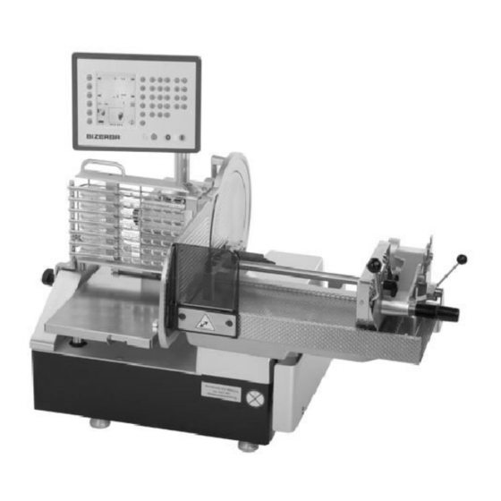
Operating Manual A400 / A400FB General Overview/Identification of components A400 1 Blade guard ring 11 Rating plate 2 Blade 12 Receiving table 3 Blade cover 13 Rear wall 4 Sliced products support 14 Gauge plate 5 Sliced product holder cpl. with... - Page 8 Operating Manual A400 / A400FB General A400FB 1 Blade guard ring 11 Bench, mobile 2 Blade 12 Lock on belt support 3 Blade cover 13 Conveyor belt 4 Sliced products support 14 Light barrier 5 Sliced product holder cpl with...
-
Page 9: Technical Data
Operating Manual A400 / A400FB General Technical data The most important technical data: A402 A404 A406 Outside measurements = 850 x 800 mm = 1050 x 800 mm = 1255 x 800 mm Work surface = 1010 x 850 mm... - Page 10 Operating Manual A400 / A400FB General The most important technical data: A402FB A404FB A406FB Outside measurements = 850 x 1710 mm = 1050 x 1710 mm = 1255 x 1710 mm Height = 1370 mm / 1535 mm Conveyor belt, applicable length...
-
Page 11: Device Description, A400/A400Fb Slicer
A406FB = Conveyor belt design with 600 mm carriage All versions are available with a mobile bench. The A400 / A400FB is a slicer that automatically feeds, slices and deposits according to the respective program that is set. This slicer is equipped with a power--driven carriage with automatic sliced product feed and depositing system. - Page 12 Operating Manual A400 / A400FB General The following are termed as protective and safety facilities: - - Blade guard ring, fixed, not removable - - Blade cover, fixed, removable - - Gauge plate, to cover stroke - - Rear wall, not removable - - Protective cover for carriage guide, to cover stroke - - Autom.
-
Page 13: Sliced Product, Application Area, Ambient Influences
Operating Manual A400 / A400FB General Sliced product, application area, ambient influences The following are approved sliced products that comply with the permissible dimensions: -- Sausage of all kinds -- Ham/Bacon -- Smoked meats with/without rind -- Roast meats/Roast beef... -
Page 14: Device Installation
Follow the instructions on how to unpack 6.054.49.106.00. Assembling the work table Assembly, start--up and instruction is carried out for the first time by the responsible BIZERBA customer services office or the BIZERBA trade consultant. Please take not of operating criteria. -
Page 15: Electric Connections
Operating Manual A400 / A400FB Device installation Electric connections compare existing mains voltage with the information on the rating plate if this does not correspond, under no circumstances connect the slicer to the socket but inform BIZERBA Customer Service! -- The socket must comply with the national country regulations (e.g. -
Page 16: Shaving Option
Operating Manual A400 / A400FB Device installation Shaving option In order to mount the shaving attachment to the chain frame first of all the depositing arm has to be disassembled. (see p. 5--2) The shaving attachment is secured to the chain frame by means of a triangular screw at the distance indicated in the picture. -
Page 17: Device And Operating Controls
Operating Manual A400 / A400FB Device and operating controls Device and operating controls Main switch By pressing the green switch on the operating and display panel, the machine is switched The signal lamp lights up, the display is activated, the carriage, receiving table and depositing arm move into their basic setting. -
Page 18: Keyboard
Operating Manual A400 / A400FB Device and operating controls Keyboard Function <Start/Stop slicing> ON: The machine starts to move, the set program is worked through, the LED is lit. OFF: The machine remains in its basic setting, the set program is interrupted. - Page 19 Operating Manual A400 / A400FB Device and operating controls Depositing program <Stack> (PLU1) The sliced product is deposited in a stack. Desk--top machine max. 90 mm, conveyor belt machine max. 60 mm. Depositing program <Shingle> (PLU3) The sliced product is deposited in a shingle.
- Page 20 Operating Manual A400 / A400FB Device and operating controls Program - -Keys <Open>--key Request PLU from memory. The PLU station appears in the display. <Save>--key Save new PLU to memory or overwrite or delete existing PLU. The PLU station appears in the display.
-
Page 21: Display Icons
Operating Manual A400 / A400FB Device and operating controls Display icons Slicing thickness Shingling distance lengthwise or crosswise Number of slices Number of carriage strokes Number of portions at depositing station at measuring station/sliced product length Light barrier (only on conveyor belt machine) - Page 22 Operating Manual A400 / A400FB Device and operating controls Single stack Double stack Shingle lengthwise Shingle crosswise Shingling lengthwise, several layers (only receiving table machines) Shingling crosswise, several layers (only receiving table machines) Shaving (special attachment required) Equal distribution of sliced product on receiving table...
-
Page 23: Displays, Stations
Operating Manual A400 / A400FB Device and operating controls Displays, stations Workstation This display appears after the machine has been switched on indicating the settings that were active before the machine was switched off. All numeric input can be entered via the numeric keyboard and adopted when <Enter> is pressed. - Page 24 Operating Manual A400 / A400FB Device and operating controls Depositing station This is where depositing positions are determined on the table or conveyor belt. The selected depositing position appears in the middle of the display: in the example ”Shingling, lengthwise, three--rows”.
- Page 25 Operating Manual A400 / A400FB Device and operating controls Measuring station This is where the dimensions for the sliced product are entered. In addition select one of the predefined values for sliced product length, height, width via the function keys.
- Page 26 Operating Manual A400 / A400FB Device and operating controls Information station The password is activated by entering a three--digit number, and is deactivated by entering the same number again. Display contrast <F1> <F7> Display contrast Set daily counter to zero <F2>...
- Page 27 Operating Manual A400 / A400FB Device and operating controls Open PLU station This display appears after activating the <Open> key. (Example for the receiving table machine, with PLU 1 to PLU 4) By directly selecting a PLU via the function keys or entering the PLU number and <Enter>, the data is transferred to the work station.
- Page 28 Operating Manual A400 / A400FB Device and operating controls Save PLU station This display appears after activating the <Save> key; the password is required when activated. (Example for the receiving table machine, with PLU 5 to PLU 8) Enter new PLU number, confirm with <Enter>, or select existing PLU via function keys;...
- Page 29 Operating Manual A400 / A400FB Device and operating controls Sharpening station This display appears after activating the <Sharpening> key. Comment: Exit the sharpening station by pressing the <Cleaning> key. Mount sharpener. <F7>Blade on <F9> Blade off _______________________________________________________________________ CAUTION Open blade! Cut- -injuries Wear cut--resistant gloves.
- Page 30 Operating Manual A400 / A400FB Device and operating controls Cleaning station This display appears after activating the <Cleaning> key. Comment: Do not switch off machine yet. Table, product feed, slicing thickness and depositing arm run in the cleaning setting. Do not tilt out carriage until you hear a clear ”Clack” sound.
-
Page 31: Paper Holder
Operating Manual A400 / A400FB Device and operating controls Paper holder The paper holder is used when the sliced product has to be deposited straight on to paper or foil. Inserting several sheets of paper or foil: Press the lever with your thumb to the right against the spring until it clicks into place. -
Page 32: Device Operation/Slicing
Operating Manual A400 / A400FB Device operating/slicing Device operation/slicing Insert long sliced product The machine is switched on, all functioning parts are in or move into their basic setting. 4.1.1 Carriage 200/400 mm with sliced product holder, feed carriage and clamping facility Hold on to the handle of the sliced product holder. -
Page 33: Carriage 600 Mm
Operating Manual A400 / A400FB Device operating/slicing 4.1.2 Carriage 600 mm with sliced product holder: Position the sliced product with the left hand against the rear wall of the carriage and press against the holder and downwards towards the hooks. -
Page 34: Slicing
Operating Manual A400 / A400FB Device operating/slicing Slicing The machine may not be operated without a table or conveyor belt. Select and enter the required functions and delivery programs via the foil keyboard of the operation and display panel. Start the machine drive, press <start/stop slicing>. -
Page 35: Cleaning
Operating Manual A400 / A400FB Cleaning Cleaning Clean thoroughly: Before putting into operation, according to application and use, several times a day if heavily contaminated, after sharpening and after long down--times. Do not clean the machine with a steam jet or similar device! Cleaning preparation Press the <Cleaning>... -
Page 36: Cleaning 5
Operating Manual A400 / A400FB Cleaning Remove components as follows: Receiving table (only for receiving table machines) Use both hands on the operator side to lift it up a little and pull towards you. Conveyor belt (only conveyor belt machines) Pull the light barrier upwards out of the holder and hang in to the holder of the machine. - Page 37 Operating Manual A400 / A400FB Cleaning Use both hands to hold on to the sides of the center of the conveyor belt and tilt it towards you and then lift it up. Place the belt carefully on to an even surface.
- Page 38 Operating Manual A400 / A400FB Cleaning Chain frame _______________________________________________________________________ CAUTION Risk of injury at chain points! Wear cut--resistant gloves. _______________________________________________________________________ Move the feed roller with the right hand to the left first of all and then hold it. Lift the connected chain frame out of the bearing with the left hand.
- Page 39 Operating Manual A400 / A400FB Cleaning Sliced product holder (200/400 mm carriage) Loosen star grip screw and pull up holder housing. Feed carriage (200/400 mm carriage) Hold on to the handle of the sliced product holder. Loosen lock lever and move upwards until it locks into place.
- Page 40 Operating Manual A400 / A400FB Cleaning Blade cover Place widely--spanned right hand on the cover. Use the left hand to unscrew the attachment bolts on the triangular handle and push out of center by applying pressure to the bolts. Tilt out the cover on to the span of your hand, and remove upwards.
- Page 41 Operating Manual A400 / A400FB Cleaning Cleaning Clean removable and non- -removable parts according to the cleaning plan. _______________________________________________________________________ CAUTION Risk of injury at chain- -, driver- -, and grip hooks! Wear cut--resistant gloves. _______________________________________________________________________ Blade Press a wet disposable cleaning cloth against the blade surface and slowly wipe away from the center.
-
Page 44: Preparing The Machine For Operation
Operating Manual A400 / A400FB Cleaning Preparing the machine for operation (attach the parts that have been removed and cleaned) Assembly of the machine takes place in the reverse order in which parts were removed to prepare for cleaning. (See Chapter 5.1) To avoid annoyance and injuries, assembly must be carried out carefully and conscientiously. - Page 45 Operating Manual A400 / A400FB Cleaning Carriage Move the carriage and screw tight to the carriage base with the star grip screw. Sliced product holder (600 mm carriage) Insert the holder housing into the channel along the sliced product holder guide and screw tight with the star grip screw.
- Page 46 Operating Manual A400 / A400FB Cleaning Guide cog _______________________________________________________________________ CAUTION Risk of injury at chain points! Wear cut--resistant gloves. _______________________________________________________________________ Insert between the transport chain and screw tight via the handle. By turning the fee roller check that the chains are mounted correctly.
- Page 47 Operating Manual A400 / A400FB Cleaning Depositing arm _______________________________________________________________________ CAUTION Risk of injury at chain points! Wear cut--resistant gloves. _______________________________________________________________________ Push on to the driver shaft and turn until the boss catches the channel. Screw tight with the star grip screw.
- Page 48 Operating Manual A400 / A400FB Cleaning Push the belt as far as it will go towards the connection, if necessary turn the drive shaft until it connects with the connection bolts. Secure the conveyor belt by setting the lock at the belt support.
-
Page 49: Sharpening The Knife
Clean before sharpening with a brush and cleaning agent. In the event that the grinding bead has been worn down from use, the stones have to be replaced. Replacement delivery available by the BIZERBA customer services. Do not muddle the stones when replacing them. Preparing the sharpening process Press the <Cleaning>... -
Page 50: Sharpening 6
Sharpening the knife Operating Manual A400 / A400FB Swing the deflector into a horizontal position (ca. 90_). Switch on machine. Press the <Sharpening> key. The slicing thickness opens up completely and the following picture appears in the display: <F7> Blade on <F9>... -
Page 51: Sharpening
Sharpening the knife Operating Manual A400 / A400FB Hold on to the device in this position and use the star grip screw to clamp it to the stop plate. Sharpening Start the blade motor with the <F7> key. Set the manual wheel marking to ”1”. -
Page 52: Remove Sharpening Device
Sharpening the knife Operating Manual A400 / A400FB _______________________________________________________________________ Remove sharpener immediately. _______________________________________________________________________ Remove sharpening device. Loosen the clamp connection via the star grip screw, Move the device upwards and hang it out of the holes Exit the sharpening program Press the <Cleaning>... - Page 53 Sharpening the knife Operating Manual A400 / A400FB Blade guard ring Thread a dry disposable cleaning cloth into the front between the blade and the guard ring. Use your hands to turn the blade and the disposable cleaning cloth; while you are doing so, press the cloth lightly against the inside of the guard ring.
-
Page 54: Servicing/ Maintenance
Operating Manual A400 / A400FB Servicing/Maintenance Servicing/ Maintenance Resharpen blade if necessary. When necessary, clean or exchange the grinding stones. Caution! Left- -handed thread! _______________________________________________________________________ At an annular gap of > 6mm between the blade and the guard ring, the grinding device no longer has a grinding effect and the blade has to be replaced. -
Page 55: Special Accessories
Operating Manual A400 / A400FB Servicing/Maintenance Special accessories Order number Bench 60542420000 Cheese blade 60530105300 7 -- 2 6.054.98.5.10.04... -
Page 56: Operating Conditions
Operating Manual A400 / A400FB Operating conditions Operating conditions 10.1 EC Directives/Norms and Recommendations Depending on the country, the machines fulfil the following requirements: machine directive 98/37/EC EMC Directive 89/336/EEC Low Voltage Directive 73/23/EEC Norms: DIN EN 55011, DIN EN 60204--1... -
Page 57: Air Convection
Operating Manual A400 / A400FB Operating conditions Technical data for the mains power supply Mains connection Single--phase alternating current or three--phase current, see rating plate. Permissible mains voltage tolerance (steady- -state) normal: At 100 to 400 V+6% to --10% of nominal value... -
Page 58: Annex
Operating Manual A400 / A400FB Annex Annex Set programs Declaration of conformity A400 Declaration of conformity A400FB 6.054.98.5.10.04 9 -- 1... - Page 59 Operating Manual A400 / A400FB Annex 9 -- 2 6.054.98.5.10.04...
- Page 60 Set programs Slicer A400 (Receiving table) Slicer A400FB (Conveyor belt) 6.054.98.5.10.04...
- Page 61 DIN EN 1974 The declaration of type conformity is based on contractual documents (Bizerba order documents). Any modification made to the above device type without the prior permission of Bizerba or by Bizerba staff will render thisdeclaration invalid. Date: 04.07.2006 Manufacturer Signature: ppa.
- Page 62 DIN EN 1974 The declaration of type conformity is based on contractual documents (Bizerba order documents). Any modification made to the above device type without the prior permission of Bizerba or by Bizerba staff will render thisdeclaration invalid. Date: 04.07.2006 Manufacturer Signature: ppa.
Need help?
Do you have a question about the A400 and is the answer not in the manual?
Questions and answers
ON A Bizerba A 404 FB S/N 1715320 WHAT IN WRONG WHEN ERROR 210 Comes on ,on the screen