Table of Contents
Advertisement
Advertisement
Table of Contents

Related Manuals for Bizerba VS 12 D-V


Summary of Contents for Bizerba VS 12 D-V
- Page 1 OPERATING INSTRUCTIONS MODEL VS 12 D–V VS 12 D–V/R 6.083.98.5.14.00...
- Page 2 Alle Rechte vorbehalten All rights reserved Tous droits réservés Reservados todos los derechos Tutti i diritti riservati © 2003 Bizerba GmbH & Co. KG 72336 Balingen Postfach 10 01 64 72301 Balingen/Germany Tel. (07433) 12–0, Fax (07433) 122696 E–mail: marketing@bizerba.de Internet: http://www.bizerba.com...
- Page 3 We declare herewith that the type of the machine described below Any modification made to the machine described above without the prior Definition: Slicer permission of Bizerba will render this declaration invalid. Type: VS 12 D–V, VS 12 D–V/R Notified body, verifying and certifying body Notified body complies –...
- Page 4 6.083.98.5.14.00 VS 12 D–V OPERATING INSTRUCTIONS VS 12 D–V/R...
-
Page 5: Table Of Contents
CONTENTS PAGE PAGE GENERAL ....... Slice thickness setting ......Unlocking of slice thickness control knob . - Page 6 6.083.98.5.14.00 PAGE PAGE CLEANING ......ACCESSORIES ......Preparing for cleaning .
-
Page 7: General
Training should be repeated. S Equipment should not be started up before S BIZERBA does not accept liability for the requirements of the Bizerba operating damage arising as a result of installation by conditions are met. -
Page 8: Warning Notice
S Do not tamper with any protective devices is any rough operation or obstruction. of the machine. Do not remove, change or S Contact the relevant BIZERBA after–sales bypass them. It may result in serious bodily service if you cannot eliminate occurring injury. -
Page 9: Overview/Component Description
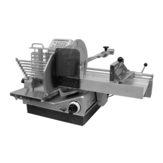
Three–square knob for depositing arm Gauge plate Carriage Deflector Receiving table with paper grip Specification plate Table guide Slice thickness unlocking device Slice thickness control knob Accessory kit (not illustrated), containing: sharpener, special cardboard, cloth, handbrush with special flat brush, BIZERBA oiler 6.083.98.5.14.00... -
Page 10: Dimensional Drawing/Technical Data
6.083.98.5.14.00 Dimensional drawing/technical data VS 12 D–V THE MOST IMPORTANT TECHNICAL DATA Weight = ca. 72 kg = ca. 158 lbs Blade diameter = 330 mm = 13” Number of blade revolutions = 266 r.p.m. Number of carriage strokes = approx. 30 – 60 strokes/minute Product size with depositing arm –round = min./max. -
Page 11: Machine Description
GENERAL Machine description The VS 12 D–V can be operated in an The complete machine housing, the gauge A slice thickness setting of less than ’0’ automatic mode only. plate, the blade cover and the carriage are unlocks the tilting safety device allowing the This means carriage movement and product made of anodized aluminium. -
Page 12: Products To Be Cut/Application/Environmental Influences
6.083.98.5.14.00 Products to be cut/application/environmental influences Note Humidity Products permitted for cutting by taking S If mainly cutting cheese, the use of a S Protection type IP 33. High air humidity or into account the permitted sizes: special cheese knife is recommended. moisture condensation occurring on the See optional equipment. -
Page 13: Installation
Electrical connection the packaging. S Compare the voltage of outlet with that on the specification plate. S Do not connect the machine in case of non–conformity. Contact BIZERBA after–sales service. S The connector should meet country–specific standards (see section 8.2, page 54). -
Page 14: Test Run
6.083.98.5.14.00 Test run Test run or checking the direction of rotation (in the case of three–phase current): S Switch on the machine (see section 3.1, page 12). S The pilot lamp lights up (startup control). S The blade must rotate in the direction of arrow. -
Page 15: Operating Elements
OPERATING ELEMENTS Keyboard/display Description of key functions: Display ON (green) mains on LAMP (white) Indicates the ON/OFF position Function keys of the machine OFF (red) Deactivates the machine (reacts at a slight touch = EMERGENCY OFF) Set the maximum number of strokes Reduce the number of carriage strokes step–by–step Set the full stroke... - Page 16 6.083.98.5.14.00 Display Display of number of slices Number of slices Number of portions Display U = continuous operation without counting infinite number of slices Display 1 – 99 = slices counted towards zero Display of number of portions Display P 1 = 1 portion Display P U = continuous operation without counting...
- Page 17 OPERATING ELEMENTS Function keys PLUS key Input key to increase the number of slices or portions. Overflow of number of slices from 99 to 1 (instead of 100) Overflow of number of portions from P9 to P1 (instead of 10) MINUS key Input key to reduce the number of slices or portions.
- Page 18 6.083.98.5.14.00 Depositing modes Depositing in ’1 stack’ with the number of portions P 1, number of slices U (infinite) and the depositing position on the right of the receiving table. Stack height up to maximum 60 mm. Depositing in ’2 stacks’ with the number of portions P 2, number of slices U (infinite) and the depositing position on the right of the receiving table.
- Page 19 OPERATING ELEMENTS Depositing modes Product depositing on the right or large product diameter, deposition of product on the right of the receiving table. Exception: depositing program ’shingling crosswise’ deposition at the rear of the receiving table depositing program ’circular pattern’ 5 slices/circle = small circle diameter Product depositing in the center or medium product diameter,...
-
Page 20: Individual Setting Of Depositing Programs
6.083.98.5.14.00 3.1.1 Individual setting of depositing programs All depositing programs are normally set and stored with an individual number of slices and portions. This applies equally to their positioning. Key combination for storing: hold pressed and activate Restoring the delivery state: hold pressed and activate The program stored last before the machine is switched off will become active (startup program) when restarting the machine. - Page 21 OPERATING ELEMENTS Example Example of a self–compiled program Operating or key sequence: P 1 0 8 1. The depositing mode ’shingling lengthwise’ is activated. P 1 1 2 2. Number of slices – make the entry using the +/– keys, e.
-
Page 22: Setting Of Distance Between Slices
6.083.98.5.14.00 3.1.2 Setting of distance between slices Using the depositing programs “Shingling lengthwise” and “Shingling crosswise” the distance between slices is set inevitably, de- pending on how many slices are required (see table, rounded values). Distance between slices Distance between slices Number of slices Shingling lengthwise Shingling crosswise... -
Page 23: Slice Thickness Setting
OPERATING ELEMENTS Slice thickness setting The setting is made by means of the slice thickness control knob. Large fine setting range: between 0 and 3 mm. A setting of less than ’0’ deactivates the tilting safety device (black marking). This is the only position in which the carriage can be tilted, an operation which may become necessary for cleaning purposes. -
Page 24: Product Holder
6.083.98.5.14.00 Product holder To insert the product, the product holder with moveable hooks (spikes) may be locked or unlocked. Before the cutting procedure the product holder is positioned behind the product. Product holder can be removed during cleaning process. Product support An additional product support on side avoids overbalance of the product. -
Page 25: Paper Grip
OPERATING ELEMENTS Paper grip The paper grip is used to deposit the cut product directly on the paper or the foil. To insert several paper sheets or foils: S Push the lever to the right against the pressure spring using your thumb until you feel it engage (1). -
Page 26: Circular Plate
6.083.98.5.14.00 Circular plate Option This machine permits a circular plate to be attached to the additional guide shaft (see section 4.2, page 28). For an easy and fast handling the circular plate is fixed to the guiding shaft by means of a magnetic lock. -
Page 27: Operation/Slicing
OPERATION/SLICING Positioning/slicing of product S The machine is turned on, all function parts are in a stop position. S Disengage the product holder using the locking lever, move it away from the blade. Positioning of product S The product support may be raised up in order to position the product. - Page 28 6.083.98.5.14.00 Positioning of product S Using your left hand position the product so that it rests on the carriage rear wall and push it against the holder. S Using your right hand push down the lever on holder. Spikes/hooks go into the product and fix them.
- Page 29 OPERATION/SLICING Slicing of product S Start the carriage drive. S The carriage starts moving. S Depending on the program setting, the slices are deposited on the receiving table. The drive is automatically turned off: S on EMERGENCY OFF S when the maximum stack height or the number of slices is reached.
- Page 30 6.083.98.5.14.00 OPERATING BLADE OPERATION/ OPERATING GENERAL INSTALLATION CLEANING ACCESSORIES SLICING CONDITIONS ELEMENTS SHARPENING...
-
Page 31: Option: Circular Plate
OPERATION/SLICING Option: circular plate This machine permits a circular plate to be easily installed. Rectangular products can only be deposited in a circular pattern with the aid of this circular plate. Attaching of circular plate S Move the receiving table up to the stop, raise it to a vertical position towards you and remove it in the upward direction. - Page 32 6.083.98.5.14.00 Setting possibility Standard presetting: depositing program ’circular’ with 5 slices/circle and a large product diameter. The number of slices may be changed up to a maximum of 99 slices per circle and circle diameter. To obtain the adjacent pattern, the number of slices must be increased accordingly.
-
Page 33: Cleaning
CLEANING Preparing for cleaning S Switch off the machine. S Disconnect the power plug. S Set the slice thickness control knob to less than ’0’ (black marking). Thoroughly clean the machine before initial operation and after each use. If necessary, clean it several times a day. - Page 34 6.083.98.5.14.00 Circular plate Option S Lift the circular plate out of the guide shaft and remove it in the upward direction. For an easy and fast handling the circular plate is fixed to the guiding shaft by means of a magnetic lock.
- Page 35 CLEANING Depositing arm S Loosen the three–square knob and pull the hub of the depositing arm out of the bearing to the left. Caution Danger of injury by the chain spikes! Chain frame S Using the right hand, turn the feed roller to the left and hold it firmly.
- Page 36 6.083.98.5.14.00 Guide cam S Loosen the clamp handle on the frame and remove the guide cam from between the transport chains. Caution Danger of injury by the chain spikes! A bent cam or deformed chain pikes will give rise to operational disturbances.
- Page 37 CLEANING Product support S Remove the product support by loosening the star knob. 6.083.98.5.14.00...
- Page 38 6.083.98.5.14.00 Carriage S Turn out the knob on the carriage foot. S Tilt the carriage in the direction of arrow. Blade cover S Grasp the bracket using the right hand. S Using the left hand, loosen the fixing bolt by means of the three–square knob and push the blade cover out of centering.
-
Page 39: Cleaning
CLEANING Deflector S Remove the deflector from the magnetic lock and move it away in the direction of arrow. Cleaning Blade cleaning Do not attempt to clean blade surfaces while the machine is running. S Clean the front of blade by pressing a wet disposable cloth against the blade surface and slowly wiping from the center outward. - Page 40 6.083.98.5.14.00 Blade guard ring S Insert a damp disposable cloth between the blade and guard ring from the front. S Turn the blade and disposable cloth with hands for one rotation by slightly pressing the cloth against the guard ring inner side. Clean removable and non–removeable parts according to the cleaning plan (section 5.3, page 38).
-
Page 41: Cleaning Plan Vs 12 D-V
CLEANING Cleaning plan VS 12 D–V (the operating instructions should be observed) Steps Cleaning agents Procedure Cleaning equipment Hints and tips Set slice thickness below zero 1 Preparatory measures Switch off machine Disconnect power plug Dismantling According to the operating instructions of removable parts Manual removal of product... - Page 42 P3–steril 50003250000 5 Liter agents must be observed. P3–riksan 50003270000 5 Liter Bizerba cannot accept liability for damage P3–alcodes 50003260000 5 Liter Clean Station 50003280000 occurring as a result of the use of cleaning H1–Service–Oil...
-
Page 43: Making The Machine Ready To Operate
Making the machine ready to operate CLEANING (reassemble the components as follows) Deflector S Swing the deflector down up to the magnetic lock by ensuring a proper seating in the recess of the blade guard ring. Proceed carefully avoid disturbances and injuries. - Page 44 6.083.98.5.14.00 Carriage S Swing in the carrriage in the direction of arrow. S Fasten it to the carriage foot by means of the knob. Product support S Move the product support to the guiding de- vice S and tighten it with the star knob. OPERATING OPERATION/ BLADE...
- Page 45 CLEANING Product holder S Put the product holder in the direction of arrow on the fixation S and tighten it with the star knob. Caution! Danger of injury on product holder (hooks/spikes)! 6.083.98.5.14.00...
- Page 46 6.083.98.5.14.00 Guide cam S Insert the guide cam between the transport chains and fasten it by means of the clamp handle. Caution Danger of injury by the chain spikes! A bent cam or deformed chain pikes will give rise to operational disturbances.
- Page 47 CLEANING Depositing arm S Move the depositing arm on the drive shaft and turn it, so that the hub engages with the slot. S Tighten it by means of the three–square knob. Caution Danger of injury by the chain spikes! Receiving table S Move the table guide towards you.
- Page 48 6.083.98.5.14.00 Circular plate Option S Insert the circular plate in the guide shaft from the top. For an easy and fast handling the circular plate is fixed to the guiding shaft by means of a magnetic lock. S If necessary, turn the circular plate until it engages in the toothing.
-
Page 49: Blade Sharpening
It as the sharpening rim is worn. New stones are consists of one coarse sharpening stone and to be obtained from the BIZERBA after sales one fine honing stone. Dirty sharpening service. Do not mix them up when replacing stones do not have the abrasive quality them. -
Page 50: Attaching Of Sharpener
6.083.98.5.14.00 Attaching of sharpener S Unlock the slice thickness limitation (see section 3.3, page 20) S Set the slice thickness control knob to position ’24’ or open it up to the stop. S Set the handwheel of sharpener to position ’0’. -
Page 51: Sharpening
BLADE SHARPENING Sharpening S Switch on the machine. S Set the handwheel of sharpener to position ’1’. S The sharpening stone engages. Checking of burr: S Sharpen until the right–hand blade edge with the aid of a pen, or a ball–point pen, or similar check shows a burr. -
Page 52: Removing Of Sharpener
6.083.98.5.14.00 Removing of sharpener S Loosen the knob and remove the sharpener in the upward direction. S Immediately turn the slice thickness control knob to ’0’. Caution Danger of injury by exposed blade! OPERATION/ BLADE OPERATING OPERATING GENERAL INSTALLATION CLEANING ACCESSORIES SLICING SHARPENING... -
Page 53: Removing Of Sharpening Dust
BLADE SHARPENING Removing of sharpening dust Blade S Set the slice thickness control knob to ’0’. S Tilt the carriage. S Clean the blade by pressing a dry disposable cloth against the blade surface and slowly wiping from center outward. Do not attempt to clean blade surfaces while the machine is running. - Page 54 6.083.98.5.14.00 S Turn the blade and the disposable cloth with the hand for one rotation by pressing the cloth against the inner side of guard ring. Machine housing S Remove the sharpening dust from the surfaces with a dry disposable cloth or a brush.
-
Page 55: Accessories
For safety reasons, have the blade replaced only by BIZERBA after sales service. Slightly 1 the product holder guide and 2 the toothed rack on the table guide once a week with the BIZERBA oil contained in the accessory kit. 6.083.98.5.14.00... -
Page 56: Disturbances
6.083.98.5.14.00 Disturbances Immediately switch the machine off if there is any rough operation or obstruction. Contact the relevant BIZERBA after–sales service if you cannot eliminate occurring malfunctions yourself. Optional equipment Order number Cheese knife, hard chromium–plated 60223507600 Non–stick coated knife... -
Page 57: Operating Conditions
International Electrotechnical Commission Bizerba equipment manufactured connection of BIZERBA equipment must be (IEC) according to VDE protection class I and must carried out in compliance with the national be connected to a ground wire. European Committee for Electrotechnical... -
Page 58: Air Convection
Permitted tolerance of power supply (static): the user may take the following precautions: At 100 to 400V + 6% to – 10% of nominal value Provide a separate power supply to BIZERBA Power frequency: 50 (60) Hz equipment. Install a capacity–decoupled isolating transformer or similar device in the + 2% to –...
Need help?
Do you have a question about the VS 12 D-V and is the answer not in the manual?
Questions and answers