Vermeiren Club Installation Manual
Hide thumbs
Also See for Club:
- User manual (116 pages) ,
- Installation manual (140 pages) ,
- User manual (164 pages)
Table of Contents
Advertisement
Quick Links
Installation manual
M A N U E L
D ' I N S T A L L A T I O N
I N S T A L L A T I E H A N D L E I D I N G
I N S T A L L A T I O N S A N L E I T U N G
M A N U A L E
D I
I N S T A L L A Z I O N E
M A N U A L
D E
I N S T A L A C I Ó N
I N S T R U K C J A
I N S T A L A C J I
P Ř Í R U Č K U
P R O
I N S T A L A C I
Club
Advertisement
Table of Contents

Subscribe to Our Youtube Channel
Related Manuals for Vermeiren Club


Summary of Contents for Vermeiren Club
- Page 1 I N S T R U K C J A I N S T A L A C J I P Ř Í R U Č K U P R O I N S T A L A C I Club...
-
Page 3: Table Of Contents
Club 2023-05 Content Content Content ........................... 1 Preface ........................... 2 This product ......................3 Scope of delivery ...................... 4 Assembly ........................5 Tools ........................... 5 Assembling the bed ....................6 Strain relief and power cable ..................10 Cable placement ......................11 Transport........................ -
Page 4: Preface
To support you on the installation and repairs of this nursing bed, we provide you with this installation manual. Please read it carefully. If you still have questions after reading this manual, do not hesitate to contact Vermeiren. The information in this manual applies to the following bed(s): ... -
Page 5: This Product
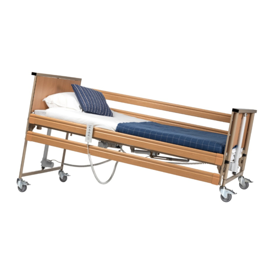
Club 2023-05 This product This product 1. Head panel 2. Mattress retainer 3. Foot panel 4. Castor 5. Foot end 6. Head end 7. Identification plate Installation manual... -
Page 6: Scope Of Delivery
Club 2023-05 Scope of delivery Scope of delivery The following components are part of the delivery: Head and feet end incl. motors Slatted frame, foot-end incl. motor Slatted frame, head-end incl. transformer and motor Handset Instruction manual ... -
Page 7: Assembly
Prevent trapping your hands when assembling, disassembling or using the bed. Make sure that no body parts or objects are present when adjusting hinges, joints or other clamps. Only use genuine spare or replacement parts approved by Vermeiren. Important remarks ... -
Page 8: Assembling The Bed
Follow the order of assembly as explained below. 3.2.1 Head panel / feet panel Club 1. Slide the attachment tube of the head panel (4) into the tube of the slatted frame (3). 2. Secure the slatted frame (1) with the star knobs (2). - Page 9 2023-05 Assembly 3.2.3 Head panel / Feet panel Club 1. Mount the attachment of the slatted frame (3) on the attachment of the head panel (4). 2. Secure the slatted frame (1) with the locking clamps (5). 3. Repeat for the feet panel. Make sure that the slatted frames are mounted securely.
- Page 10 Club 2023-05 Assembly 1. Remove the star knobs (2). 2. Insert the connector (3) into the frame tubes of the foot and head slatted frame. Make sure it is oriented correctly: the holes in the inner and outer tubes have to align to insert the star knobs, see image.
- Page 11 3. Insert the bolts (4) and tighten them. 4. Repeat these steps for the other side. 3.2.6 Metal side rails (not for Club 1. Place the hooks (1) over the frame tube (2). 2. Tighten the star knob (3).
-
Page 12: Strain Relief And Power Cable
Club 2023-05 Assembly 1 = Connection of panels motor 2 = Connection of knee-bending angle motor 3 = Connection of head-end motor 4 = Connection of foot-end motor 5 = Handset 6 = Transformer / control box The motor connection plugs are labelled with the same number as the connections on the transformer. -
Page 13: Cable Placement
Club 2023-05 Assembly Cable placement Mattress slatted frame head end Mattress slatted frame feet end Sockets lifting pole Strain relief Power supply Control box Head end motor Knee-bend motor 4 3 2 1 Head panel motor 10. Feet panel motor 11. - Page 14 Club 2023-05 Assembly 3.5.1 Vertical transport set (Club ; Club Vario Club 1. Grasp the panels (1). 2. Mount the attachment of the transport set (2) in the attachment of the panels (3). 3. Grasp the head end (4) and hold this with the motor located to the bottom side.
- Page 15 Club 2023-05 Assembly Club Vario 1. Grasp the panels (1). 2. Mount the attachment of the transport set (2) in the attachment of the panels (3) and lock with the locking clamps (4). Mount the transport set in the lowest position of the panels.
- Page 16 4. Repeat the steps above for the foot end. 5. Grasp the head and foot panel. 6. For Club Vario, Club UL: Mount the panel attachments (4) to the hooks (5) of the transport set (for Club : use the lowest attachment). Lock with the locking clamps.
-
Page 17: Lifting Pole (Optional)
Club 2023-05 Assembly Lifting pole (optional) The lifting pole can be mounted on either side of the head end. 1 = Lifting pole 2 = Socket 3 = Groove 4 = Upper frame lifting pole 5 = Strap 6 = Triangle 1. - Page 20 Vermeiren GROUP Vermeirenplein 1 / 15 2920 Kalmthout website: www.vermeiren.com Instructions for specialist dealer This instruction manual is part and parcel of the product and must accompany every product sold. Version: A, 2023-05 Basic UDI: 5415174Club99 All rights reserved, including translation.
Need help?
Do you have a question about the Club and is the answer not in the manual?
Questions and answers