Table of Contents
Advertisement
Advertisement
Table of Contents

Related Manuals for Qvis APOIP-MB


Summary of Contents for Qvis APOIP-MB
- Page 1 APOIP-MB APOIP-MB2 1.3 & 2 MEGA PIXEL BULLET IP CAMERAS User’s Manual...
- Page 3 Welcome Thank you for purchasing the 1.3 or 2 Mega Pixel Bullet IP Cameras. This user’s manual is designed to be a reference tool for the installation and operation of your system. Here you can find information about the corresponding IP camera’s features and functions, as well as a detailed installation method.
- Page 4 Important Safeguards and Warnings 1.Electrical safety All installation and operation here should conform to your local electrical safety codes. The power supply shall conform to the requirement in the SELV (Safety Extra Low Voltage) and must make sure that the limited power source is rated 12V DC or 24V AC. Please note: Do not connect two power supplying sources to the device at the same time;...
- Page 5 Please make sure the CCD (CMOS) component is away from the radiation of the laser beam device. Otherwise it may result in CCD (CMOS) optical component damage. It is recommended that the grounding studs of the product should be grounded, so to further enhance the reliability of the camera.
-
Page 6: Table Of Contents
Factory Default Setup ..................4 Structure ........................9 APOIP-MB2: Multiple-function Combination Cable ........... 9 APOIP-MB2: Framework and Dimension ............10 APOIP-MB: Multiple-function Combination Cable ........... 11 APOIP-MB: Framework and Dimension ............12 Device Installation ....................... 13 Quick Configuration Tool ..................... 15 Overview ...................... -
Page 7: General Introduction
External power adapter DC12V. Supports s PoE supply Warning! Power Do not connect these two power supplying sources to the device at the same time; it may result in device damage! © Copyright Qvis ®. All documentation rights reserved. -
Page 8: Specifications
Main stream(1280*960@15fps), Main extra stream (352*288@15fps) stream(1920*1080@25fps), Main stream(1280*720@25fps), extra stream (704*576@25fps) Video Frame extra stream (704*576@25fps) Rate NTSC: NTSC: Main Main stream(1280*960@15fps), stream(1920*1080@30fps), extra stream(352*240@15fps) extra stream(704*480@30fps) Main stream(1280*720@30fps), extra stream(704*480@30fps) © Copyright Qvis ®. All documentation rights reserved. - Page 9 IR light 20-30M. Power DC 12V power and PoE. Power 6.5 W MAX 6W MAX Consumption Working C~+60 Temperature Working 10%~90% Humidify Dimensions(mm) 70*66*160 62.9*64.3*146.8 Weight 500g(Excluding box) 370g(Excluding box) Installation Bracket installation © Copyright Qvis ®. All documentation rights reserved.
-
Page 10: Factory Default Setup
8192 4096 Watermark Enable Watermark DigitalCCTV character Enable Enable Bit stream General type Encode H.264B mode PAL:CIF(352*288) PAL:CIF(352*288) Stream Resolution NTSC:CIF(352*240) NTSC:CIF(352*240) Frame Rate PAL:25 PAL:25 (FPS) NTSC:30 NTSC:30 Bit Rate Type © Copyright Qvis ®. All documentation rights reserved. - Page 11 IP Version IPV4 IP Address 192.168.1.108 Subnet 255.255.255.0 Mask TCP/IP Default 192.168.1.1 Gateway Preferred 8.8.8.8 Alternate 8.8.8.8 Enable ARP/Ping device Enable address service Connection TCP Port 37777 Connection UDP Port 37778 HTTP Port © Copyright Qvis ®. All documentation rights reserved.
- Page 12 User Name Password **** Sender none Authenticati SMTP(Email) (Encryption mode) Title IPC Message (Subject) Attachment Mail seconds Receiver Email Test Disable,interval=60 seconds Enable UPnP Disable UPnP SNMP Port SNMP public Read © Copyright Qvis ®. All documentation rights reserved.
- Page 13 Send Email Disable Snapshot Disable Enable Disable Disconnectio Record Enable Record 10 seconds Delay Enable Disable Record Enable IP Conflict Relay 10 seconds Delay Enable FTP Disable Server IP Port Username anonymity © Copyright Qvis ®. All documentation rights reserved.
- Page 14 End Time 00:00:00 of the second Monday of the month Disable NTP Server clock.isc.org Port Update 10 minutes Period Auto Reboot Enable Each 02:00 Tuesday Auto Auto Delete Maintenance Disable Old Files © Copyright Qvis ®. All documentation rights reserved.
-
Page 15: Structure
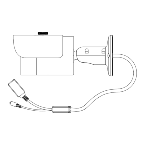
Please refer to the following sheet for detailed information: Port Name Function Connection Note Ethernet Network port Connect to standard Ethernet cable. port Power input DC12V Power input port. Input DC 12V. port © Copyright Qvis ®. All documentation rights reserved. -
Page 16: Apoip-Mb2: Framework And Dimension
2.2 APOIP-MB2: Framework and Dimension Please refer to the following two figures for dimension information. The unit is mm. See Figure 2-2 and Figure 2-3. Figure 2-2 Figure 2-3 © Copyright Qvis ®. All documentation rights reserved. -
Page 17: Apoip-Mb: Multiple-Function Combination Cable
Please refer to the following sheet for detailed information: Port Name Function Connection Note Ethernet 1.LAN Network port Connect to standard Ethernet cable. port Power input 2.DC12V Power input port. Input DC 12V. port © Copyright Qvis ®. All documentation rights reserved. -
Page 18: Apoip-Mb: Framework And Dimension
2.4 APOIP-MB: Framework and Dimension Please refer to the following two figures for dimension information. The unit is mm. See Figure 2-2 and Figure 2-3. Figure 2-5 Figure 2-6 © Copyright Qvis ®. All documentation rights reserved. -
Page 19: Device Installation
The sun shield of the device can move forward or backward. Please secure the set screw of the sun shield after you fixed the device to surface.. Step 5: Connect the corresponding cables. © Copyright Qvis ®. All documentation rights reserved. - Page 20 Use the cross-head screwdriver to loosen the adjust screw. Step 7: Turn the device in different directions to make it suitable for the monitor position. Step 8: Use the cross-head screwdriver to fix the adjust screw firmly. Figure 3-2 © Copyright Qvis ®. All documentation rights reserved.
-
Page 21: Quick Configuration Tool
The factory default user name is admin and password is admin. For security reasons, please modify your password after you first login. For detailed WEB operation, please refer to the Network Camera Web Operation Manual in the resource CD. © Copyright Qvis ®. All documentation rights reserved. - Page 22 Or you can select an IP address and then click the Login button to go to the login interface. See Figure 4-4. In Figure 4-4, you can view device IP address, user name, password and port. Please modify the corresponding information to login. © Copyright Qvis ®. All documentation rights reserved.
- Page 23 After you logged in, the configuration tool main interface is shown as below. See Figure 4-5. Figure 4-5 Main interface For detailed information and operation instructions of the quick configuration tool, please refer to the Quick Configuration Tool User’s Manual included in the resources CD. © Copyright Qvis ®. All documentation rights reserved.
-
Page 24: Web Operation
2. The login interface is shown as below. See Figure 5-2. 3. Please input your user name and password. 4. Default factory name is admin and password is admin. Note: For security reasons, please modify your password after you first login. © Copyright Qvis ®. All documentation rights reserved. - Page 25 If you can’t download the ActiveX file, please check whether you have installed the plug-in to disable the control download. Or you can lower the web browser’s security level. See Figure 5-3. Figure 5-3 IE security level © Copyright Qvis ®. All documentation rights reserved.
- Page 26 After you logged in, you can see the main window. See Figure 5-4: Figure 5-4 Web monitoring window © Copyright Qvis ®. All documentation rights reserved.
-
Page 27: Faq
Note This user’s manual is for reference only. Slight differences may be found in user interface. All the designs and software here are subject to change without prior written notice. © Copyright Qvis ®. All documentation rights reserved. - Page 28 For more information about our IP Cameras and other available cameras, NVRs & accessories, please visit our website: www.adata.co.uk Alternatively scan this QR code with your smart phone to be directed instantly to our website: © Copyright Qvis ®. All documentation rights reserved.
Need help?
Do you have a question about the APOIP-MB and is the answer not in the manual?
Questions and answers