
Related Manuals for ESAB A2SF J1


Summary of Contents for ESAB A2SF J1
- Page 1 A2 Welding heads A2SF J1 / A2SF J1 Twin A2SG J1 / A2SG J1 4WD Instruction manual 0449 175 260 20130-6-17 Valid for serial no. 940-xxx-xxxx...
- Page 2 ENGLISH ..........Rights reserved to alter specifications without notice.
-
Page 4: Table Of Contents
........4.4 Changing the feed roller (A2SF J1/ A2SF J1 Twin, A2 SG J1) . -
Page 5: Safety
SAFETY Users of ESAB welding equipment have the ultimate responsibility for ensuring that anyone who works on or near the equipment observes all the relevant safety pre- cautions. Safety precautions must meet the requirements that apply to this type of welding equipment. - Page 6 WARNING, RISK OF CRUSHING! Do not use safety gloves when replacing wire, feed rollers and wire bobbins. - 6 - SafeArcS GB...
- Page 7 WARNING ARC WELDING AND CUTTING CAN BE INJURIOUS TO YOURSELF AND OTHERS. TAKE PRECAUTIONS WHEN WELDING. ASK FOR YOUR EMPLOYER'S SAFETY PRACTICES WHICH SHOULD BE BASED ON MANU- FACTURER'S HAZARD DATA. ELECTRIC SHOCK - Can kill Install and earth the welding unit in accordance with applicable standards. Do not touch live electrical parts or electrodes with bare skin, wet gloves or wet clothing.
-
Page 8: Introduction
Welding Method 2.2.1 Submerged Arc Welding (SAW) For submerged arc welding the A2SF J1/ A2SF J1 Twin welding head is always to be used. Submerged arc Light Duty. Submerged arc light duty with a Ø 20 mm connector permits a load up to 800 A (100%). -
Page 9: Technical Data
Technical Data A2SF J1/ A2SG J1 A2SF J1 Twin (SAW) (MIG/MAG) Rated load 100% 800A 600A Wire dimensions: solid single wire 1.6-4.0 mm 0.8-2.5 mm flux-cored wire 1.6-4.0 mm 1.2-3.2 mm solid twin wire 2x1.2-2.0 mm Wire feed speed 0.2-9.0 m/min 0.2-16 m/min... -
Page 10: Main Components A2Sf J1 (Saw)
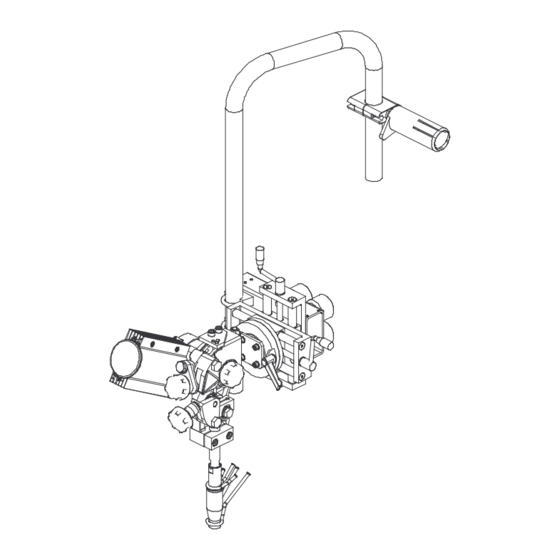
Flux hopper Slide kit, manual Wire feed motor Flux tube Slide kit, motorized Guide pin Carrier for wire drum Main components A2SF J1 Twin (SAW) Wire feed unit Connector (Twin) Flux hopper Slide kit, manual Wire feed motor Flux tube... -
Page 11: Main Components A2Sg J1 (Mig/Mag)
Main Components A2SG J1 (MIG/MAG) Wire feed unit Connector (MIG/MAG) Slide kit, manual Wire feed motor Slide kit, motorized Carrier for wire drum Main Components A2SG J1 4WD (MIG/MAG) Wire feed unit with four-wheel drive Connector (MIG/MAG) Slide kit, manual Wire feed motor Slide kit, motorized Carrier for wire drum... -
Page 12: Description Of Main Components
Description of Main Components 2.9.1 Wire Feed Unit / Wire Feed Unit with four-wheel Drive The unit is used for guiding and feeding the welding wire down into the contact tube/connector. 2.9.2 Manual and Motorized Slides The horizontal and vertical position of the welding head is adjusted by way of linear slides. -
Page 13: Installation
INSTALLATION General The installation must be executed by a professional. WARNING Rotating parts can cause injury, take great care. Mounting 3.2.1 Welding head The welding head can easily be mounted on a beam-travelling carriage or on a weld- ing column and boom unit by way of four M12 screws. N.B. -
Page 14: Adjusting The Brake Hub
3.2.3 Wire drum (Accessories) Wire drum (1) is mounted on the brake hub (2). Check that the carrier (3) is pointing upwards. NOTE! The maximum angle for the wire bobbin is 25 . At extreme angles, wear will occur on the brake hub locking mechanism and the wire bobbin will slide off the brake hub. -
Page 15: Connections
For the connection of A6 PAV, see instruction manual 0460 670 xxx. 3.4.2 Welding head A2SF J1/ A2SF J1 Twin (Submerged arc welding, SAW) 1. Connect the control cable (7) between the welding power source (8) and the PEK (2). - Page 16 3.4.3 Welding head A2SG J1 (Gas metal arc welding, MIG/MAG) 1. Connect the control cable (7) between the welding power source (8) and the PEK (2). 2. Connect the return cable (11) between the welding power source (8) and the work piece (9).
- Page 17 3.4.4 Welding head A2SG J1 4WD (Gas metal arc welding, MIG/MAG) 1. Connect the control cable (7) between the welding power source (8) and the PEK (2). 2. Connect the return cable (11) between the welding power source (8) and the work piece (9).
-
Page 18: Operation
OPERATION General WARNING: Have you read and understood the safety information ? You must not operate the machine before then ! General safety regulations for the handling of the equipment can be found on page 5. Read through before you start using the equipment! Return cable Before welding start, check that the return cable is connected. -
Page 19: Loading The Welding Wire (A2Sf J1/ A2Sf J1 Twin, A2Sg J1)
Loading the welding wire (A2SF J1/ A2SF J1 Twin, A2SG J1) A2SF J1 (SAW) A2SF J1 Twin (SAW) A2SG J1 (MIG/MAG) 1. Mount the wire drum according to the instructions on page 14. 2. Check that feed roller (1) and contact jaw or contact tip (3) are of the correct dimension for the selected wire size. -
Page 20: Loading The Welding Wire (A2Sg J1 4Wd)
8. Feed the wire forward 30 mm below the contact tip by pressing on the control box PEK. 9. Direct the wire by adjusting the knob (5). Always use a guide tube (7) to ensure even feed of fine wire (1.6 - 2.5 mm). For MIG/MAG welding with wire sizes <... -
Page 21: Changing The Feed Roller (A2Sf J1/ A2Sf J1 Twin, A2 Sg J1)
Changing the feed roller (A2SF J1/ A2SF J1 Twin, A2 SG J1) Single wire Release the knobs (3) and (4). Release the hand wheel (2). Change the feed roller (1). They are marked with their respective wire sizes. Twin wire (Twin-arc) Change the feed roller (1) with twin grooves in the same way as for single wire. -
Page 22: Contact Equipment For Submerged Arc Welding
4.6.2 For twin wires 2 x 1.2 - 2.0 mm, Light Twin (D35) Use welding head A2SF J1 Twin (SAW) where the following are included: Wire feed unit (1), Connector Twin D35 (2) Contact tip (3) (M6 thread). -
Page 23: Contact Equipment For Mig/Mag Welding
Contact equipment for MIG/MAG welding 4.7.1 For single wire 1.6 - 2.5 mm (D35) Use welding head A2SG J1 (MIG/MAG) where the following are included: Wire feed unit (1), Connector D35 (2) Contact tip (3) (M10 thread). Tighten the contact tip (3) with a key in order to ensure that a good contact is achieved. -
Page 24: Refilling With Flux Powder (Submerged Arc Welding)
(Submerged arc welding) to MIG/MAG welding For the conversion kit see instruction manual 0456 756 xxx. 4.10 Conversion of A2SF J1 (Submerged arc welding) to Twin-arc For the conversion kit see instruction manual 0456 757 xxx. - 24 - hha2o1ea... -
Page 25: Maintenance
MAINTENANCE General Note: All warranty undertakings given by the supplier cease to apply if the customer attempts to rectify any faults on the machine during the warranty period. NB! Before doing any kind of maintenance work, make sure the mains is disconnected. -
Page 26: Fault Tracing
FAULT TRACING General Equipment Instruction manual for PEK, 0460 948 xxx, 0460 949 xxx, 0459 839 036. Check that the power supply is connected for the correct mains supply that all three phases are supplying the correct voltage (phase sequence is not important) that welding cables and connections are not damaged that the controls are correctly set that the mains supply is disconnected before starting repairs... -
Page 27: Accessories
ACCESSORIES Denomination Ordering no. Fine-wire straightener 0332 565 880 Conversion kit A2 SF J1/ A2SF J1 Twin to MIG/MAG welding 0413 526 881 Conversion kit A2 SF J1 to Twin with fine-wire straightener (LD) 0413 541 882 Pilot lamp (D20) -
Page 28: Dimension Drawing
DIMENSION DRAWING A2SF J1, Manual Slide kit - 28 -... - Page 29 A2SF J1, Motorized Slide kit - 29 -...
- Page 30 A2SG J1, Manual Slide kit - 30 -...
- Page 31 A2SG J1, Motorized Slide kit - 31 -...
- Page 32 A2SG J1 4WD, Manual Slide kit - 32 -...
- Page 33 A2SG J1 4WD, Motorized Slide kit - 33 -...
- Page 34 - 34 -...
-
Page 35: Spare Parts List
SPARE PARTS LIST A2SF J1 / A2SF J1 Twin A2SG J1 / A2SG J1 4WD Edition 2009-11-10 " # "$% &'( " # "$% &'() * & + " # "$% &'() * , - " # "$% &'( "... - Page 36 Item Ordering no. Denomination Notes 0449 170 900 Welding head A2SF J1, SAW 0449 150 900 Wire feed unit complete 0449 152 880 Slide travel kit, manual 90 mm 0449 155 880 Carrier 0449 153 905 Cable unit L = 5 m 0460 909 885 Pulse transducer cable 5.0 m...
- Page 37 Item Ordering no. Denomination Notes 0449 170 901 Welding head A2SF J1, SAW 0449 150 900 Wire feed unit complete 0449 151 880 Slide kit, motorized 180 mm 0449 155 880 Carrier 0449 153 905 Cable unit L = 5 m 0460 909 885 Pulse transducer cable 5.0 m...
- Page 38 Item Ordering no. Denomination Notes 0449 170 902 Welding head A2SF J1, SAW 0449 150 900 Wire feed unit complete 0449 151 880 Slide kit, motorized 180 mm 0449 155 880 Carrier 0449 153 905 Cable unit L = 5 m 0460 909 885 Pulse transducer cable 5.0 m...
- Page 39 Item Ordering no. Denomination Notes 0449 170 903 Welding head A2SF J1, SAW 0449 150 900 Wire feed unit complete 0449 151 880 Slide kit, motorized 180 mm 0449 155 880 Carrier 0449 153 905 Cable unit L = 5 m 0460 909 885 Pulse transducer cable 5.0 m...
- Page 40 Item Ordering no. Denomination Notes 0449 170 904 Welding head A2SF J1, SAW 0449 150 910 Wire feed unit complete 0449 151 881 Slide kit, motorized 0449 155 881 Carrier 0449 153 905 Cable unit 0460 909 885 Pulse transducer cable 5.0 m...
- Page 41 Item Ordering no. Denomination Notes 0449 170 905 Welding head A2SF J1 SAW 0449 150 910 Wire feed unit complete 0449 151 881 Slide kit, motorized 0449 155 881 Carrier 0449 153 905 Cable unit 0460 909 885 Pulse transducer cable 5.0 m...
- Page 42 Item Ordering no. Denomination Notes 0449 170 906 Welding head A2SF J1 SAW 0449 150 910 Wire feed unit complete 0449 151 881 Slide kit, motorized 0449 155 881 Carrier 0449 153 905 Cable unit 0460 909 885 Pulse transducer cable 5.0 m...
- Page 43 Item Ordering no. Denomination Notes 0449 171 900 Welding head A2SF J1 Twin, SAW 0449 150 901 Wire feed unit complete 0449 152 880 Slide travel kit, manual 90 mm 0449 155 905 Carrier 0449 153 905 Cable kit L = 5 m 0460 909 885 Pulse transducer cable 5.0 m...
- Page 44 Item Ordering no. Denomination Notes 0449 171 901 Welding head A2SF J1 Twin, SAW 0449 150 901 Wire feed unit complete 0449 151 880 Slide kit, motorized 180 mm 0449 155 880 Carrier 0449 153 905 Cable kit L = 5 m 0460 909 885 Pulse transducer cable 5.0 m...
- Page 45 Item Ordering no. Denomination Notes 0449 171 902 Welding head A2SF J1 Twin, SAW 0449 150 901 Wire feed unit complete 0449 151 880 Slide kit, motorized 180 mm 0449 155 880 Carrier 0449 153 905 Cable kit L = 5 m 0460 909 885 Pulse transducer cable 5.0 m...
- Page 46 Item Ordering no. Denomination Notes 0449 171 903 Welding head A2SF J1 Twin, SAW 0449 150 901 Wire feed unit complete 0449 151 880 Slide kit, motorized 180 mm 0449 155 880 Carrier 0449 153 905 Cable kit L = 5 m 0460 909 885 Pulse transducer cable 5.0 m...
- Page 47 Item Ordering no. Denomination Notes 0449 171 904 Welding head A5SF J1 Twin, SAW 0449 150 911 Wire feed unit complete 0449 151 881 Slide kit, motorized 0449 155 881 Carrier 0449 153 905 Cable kit 0460 909 885 Pulse transducer cable 5.0 m 0461 249 885 Motor cable 5.0 m...
- Page 48 Item Ordering no. Denomination Notes 0449 171 905 Welding head A2SF J1 Twin, SAW 0449 150 911 Wire feed unit complete 0449 151 881 Slide kit, motorized 0449 155 881 Carrier 0449 153 905 Cable kit 0460 909 885 Pulse transducer cable 5.0 m...
- Page 49 Item Ordering no. Denomination Notes 0449 171 906 Welding head A2SF J1 Twin, SAW 0449 150 911 Wire feed unit complete 0449 151 881 Slide kit, motorized 0449 155 881 Carrier 0449 153 905 Cable kit 0460 909 885 Pulse transducer cable 5.0 m...
- Page 50 Item Ordering no. Denomination Notes 0449 180 900 Welding head A2SG J1, MIG/ MAG 0449 150 902 Wire feed unit complete 0449 152 880 Slide travel kit, manual 90 mm 0449 155 880 Carrier 0449 153 905 Cable kit L = 5 m 0460 909 885 Pulse transducer cable 5.0 m 0461 249 885 Motor cable...
- Page 51 Item Ordering no. Denomination Notes 0449 180 901 Welding head A2SG J1, MIG/ MAG 0449 150 902 Wire feed unit complete 0449 151 880 Slide kit, motorized 180 mm 0449 155 880 Carrier 0449 153 905 Cable kit L = 5 m 0460 909 885 Pulse transducer cable 5.0 m 0461 249 885 Motor cable...
- Page 52 Item Ordering no. Denomination Notes 0449 180 902 Welding head A2SG J1, MIG/ MAG 0449 150 902 Wire feed unit complete 0449 151 880 Slide kit, motorized 180 mm 0449 155 880 Carrier 0449 153 905 Cable kit L = 5 m 0460 909 885 Pulse transducer cable 5.0 m 0461 249 885 Motor cable...
- Page 53 Item Ordering no. Denomination Notes 0449 180 903 Welding head A2SG J1, MIG/ MAG 0449 150 902 Wire feed unit complete 0449 151 880 Slide kit, motorized 180 mm 0449 155 880 Carrier 0449 153 905 Cable kit L = 5 m 0460 909 885 Pulse transducer cable 5.0 m 0461 249 885 Motor cable...
- Page 54 Item Ordering no. Denomination Notes 0449 180 904 Welding head A2SG J1, MIG/ MAG 0449 150 912 Wire feed unit complete 0449 151 881 Slide kit, motorized 180mm 0449 155 881 Carrier 0449 153 905 Cable kit L=5m 0460 909 885 Pulse transducer cable 5.0 m 0461 249 885 Motor cable 5.0 m...
- Page 55 Item Ordering no. Denomination Notes 0449 180 905 Welding head A2SG J1, MIG/ MAG 0449 150 912 Wire feed unit complete 0449 151 881 Slide kit, motorized 180mm 0449 155 881 Carrier 0449 153 905 Cable kit L=5m 0460 909 885 Pulse transducer cable 5.0 m 0461 249 885 Motor cable 5.0 m...
- Page 56 Item Ordering no. Denomination Notes 0449 180 906 Welding head A2SG J1, MIG/ MAG 0449 150 912 Wire feed unit complete 0449 151 881 Slide kit, motorized 180mm 0449 155 881 Carrier 0449 153 905 Cable kit L=5m 0460 909 885 Pulse transducer cable 5.0 m 0461 249 885 Motor cable 5.0 m...
- Page 57 Item Ordering no. Denomination Notes 0449 181 900 Welding head A2SG J1 4WD, MIG/ MAG 0449 150 903 Wire feed unit complete 0449 152 880 Slide travel kit, manual 90 mm 0449 155 880 Carrier 0449 153 905 Cable kit L = 5 m 0460 909 885 Pulse transducer cable 5.0 m...
- Page 58 Item Ordering no. Denomination Notes 0449 181 901 Welding head A2SG J1 4WD, MIG/ MAG 0449 150 903 Wire feed unit complete 0449 151 880 Slide kit, motorized 180 mm 0449 155 880 Carrier 0449 153 905 Cable kit L = 5 m 0460 909 885 Pulse transducer cable 5.0 m 0461 249 885 Motor cable...
- Page 59 Item Ordering no. Denomination Notes 0449 181 902 Welding head A2SG J1 4WD, MIG/ MAG 0449 150 903 Wire feed unit complete 0449 151 880 Slide kit, motorized 180 mm 0449 155 880 Carrier 0449 153 905 Cable kit L = 5 m 0460 909 885 Pulse transducer cable 5.0 m 0461 249 885 Motor cable...
- Page 60 Item Ordering no. Denomination Notes 0449 181 903 Welding head A2SG J1 4WD, MIG/ MAG 0449 150 903 Wire feed unit complete 0449 151 880 Slide kit, motorized 180 mm 0449 155 880 Carrier 0449 153 905 Cable kit L = 5 m 0460 909 885 Pulse transducer cable 5.0 m 0461 249 885 Motor cable...
- Page 61 Item Ordering no. Denomination Notes 0449 181 905 Welding head A2SG J1 4WD, MIG/ MAG 0449 150 913 Wire feed unit complete 0449 151 881 Slide kit, motorized 0449 155 881 Carrier 0449 153 905 Cable kit L=5m 0460 909 885 Pulse transducer cable 5.0 m 0461 249 885 Motor cable 5.0 m...
- Page 62 Item Ordering no. Denomination Notes 0449 181 906 Welding head A2SG J1 4WD, MIG/ MAG 0449 150 913 Wire feed unit complete 0449 151 881 Slide kit, motorized 0449 155 881 Carrier 0449 153 905 Cable kit L=5m 0460 909 885 Pulse transducer cable 5.0 m 0461 249 885 Motor cable 5.0 m...
- Page 63 Item Ordering no. Denomination Notes 0449 181 907 Welding head A2SG J1 4WD, MIG/ MAG 0449 150 913 Wire feed unit complete 0449 151 880 Slide kit, motorized 180 mm 0449 155 880 Carrier 0449 153 905 Cable kit L = 5 m 0460 909 885 Pulse transducer cable 5.0 m 0461 249 885 Motor cable...
- Page 64 Item Ordering no. Denomination Notes 0449 150 900 Wire feed unit complete (Right) 0147 639 882 Wire straightener (Right) 0413 072 881 Bearing housing 0215 701 210 Wedge, flat 0413 517 001 Bracket for motor 0812 312 001 Motor with pulse transducer 0218 810 183 Insulated Hand wheel 0413 510 001 Contact tube D20, L = 260 mm...
- Page 65 Item Ordering no. Denomination Notes 0449 150 901 Wire feed unit complete (Right) SAW, Twin 0147 639 886 Wire straightener (Right) Twin 0413 072 881 Bearing housing 0215 701 210 Wedge, flat 0413 517 001 Bracket for motor 0812 312 001 Motor with pulse transducer 0218 810 183 Insulated Hand wheel 0333 852 881 Contact device Twin, L = 275...
- Page 66 Item Ordering no. Denomination Notes 0449 150 902 Wire feed unit complete (Right) MIG/ MAG 0147 639 882 Wire straightener (Right) 0413 072 881 Bearing housing 0215 701 210 Wedge, flat 0413 517 001 Bracket for motor 0812 312 002 Motor with pulse transducer 0218 810 183 Insulated Hand wheel 0417 699 001 Rubber clamp 0030 465 389 Contact device...
- Page 67 Item Ordering no. Denomination Notes 0449 150 903 Wire feed unit complete (Right) 4WD, MIG/ MAG 0456 424 902 Feed unit 0457 460 881 Contact device MTW 600, L=250 0461 238 881 Solenoid valve and cable 0156 800 002 Wire liner 0333 754 001 Hose D 14/ 6.3 0147 336 880 Hose coupling...
- Page 68 Item Ordering no. Denomination Notes 0449 150 910 Wire feed unit complete (Right) 0147 639 882 Wire straightener (Right) 0413 072 881 Bearing housing 0215 701 210 Wedge, flat 0413 517 001 Bracket for motor 0813 312 001 Motor with pulse transducer 0218 810 183 Insulated hand wheel 0417 699 001 Clamp 0413 510 004 Contact tube...
- Page 69 Item Ordering no. Denomination Notes 0449 150 911 Wire feed unit complete 0147 639 886 Wire straightener (Right) Twin 0413 072 881 Bearing housing 0215 701 210 Wedge, flat 0413 517 001 Bracket for motor 0812 312 001 Motor with pulse transducer 0218 810 183 Insulated hand wheel 0417 699 001 Clamp 0334 290 884 Contact tip...
- Page 70 Item Ordering no. Denomination Notes 0449 150 912 Wire feed unit complete 0147 639 880 Wire straightener (Right) 0413 072 881 Bearing housing 0215 701 210 Wedge, flat 3x3x16 0413 517 001 Bracket for motor 0812 312 002 Motor with pulse transducer 0218 810 183 Insulated hand wheel 0417 699 001 Clamp 0030 465 392 Contact tube...
- Page 71 Item Ordering no. Denomination Notes 0449 150 913 Wire feed unit complete 0456 424 902 Feed unit 0417 699 001 Clamp 0457 460 883 Torch water-cold .0 00 0156 800 002 Lf-hose 0333 754 001 Hose rubber 0193 761 002 Hose clamp 0147 336 880 Hose connector 0449 011 001 Support 0449 009 002 Attachment...
- Page 72 Item Orderingno. Denomination Remarks 0147 639 882 Wire straightener (right mounted) 0156 449 001 Clamp 0212 900 001 Spacer screw 0215 201 209 O-ring D11.3x2.4 0218 400 801 Pressure roller arm 0218 810 181 Handwheel 0218 810 182 Handwheel 0332 408 001 Stub shaft 0153 148 880 Roller 0415 498 001 Thrust roller carrier 0212 902 601 Spacer screw...
- Page 73 Item Ordering no. Denomination Notes 0147 639 886 Wire straightener (right mounted) 0156 449 001 Clamp 0156 530 001 Clamp half 0212 900 001 Spacer screw 0215 201 209 O-ring D11.3x2.4 0218 400 801 Pressure roller arm 0218 810 181 Handwheel 0332 408 001 Stub shaft 0218 524 580 Pressure roller Twin...
- Page 74 Item Orderingno. Denomination Notes 0413 072 881 Bearing housing with stub shaft 0413 073 002 Searing housing 0190 726 003 Ball bearing 0334 575 001 Stub shaft 0215 701 014 Betaining ring 0334 576 001 Spacer - 74 -...
- Page 75 Item Ordering no. Denomination Notes 0333 852 881 Connector Twin L=275 A6 UP 0333 772 001 Nozzle holder 0417 959 881 Contact equipment L=275, Heavy Duty 0415 032 001 Guide pipe 0334 279 001 Spiral to connector L=366 - 75 - ...0/...
- Page 76 Item Ordering no. Denomination Notes 0417 959 881 Contact equipment L=275mm 0443 372 001 Screw 0219 504 307 Beleville spring T = 1.1 0443 344 881 Pipe L = 275 - 76 -...
- Page 77 Item Ordering no. Denomination Notes 0153 299 880 Flux nozzle 0153 290 002 Pipe holder 0153 296 001 Pipe bend 0153 425 001 Wheel - 77 -...
- Page 78 Item Orderingno. Denomination Remarks 0332 994 883 Flux hopper complete 0332 837 001 Hopper for flux 0153 347 881 Flux valve 00203 017 80 Flux strainer 0443 383 002 Flux hose L= 500 - 78 -...
- Page 79 Item Ordering no. Denomination Notes Flux valve /.. 0 & - 79 - /.. !
- Page 80 Item Ordering no. Denomination Notes 0145 787 880 Fine wire straightener for twin wire 0145 788 001 Case 0145 789 001 Roller 0145 790 001 Roller 0145 791 001 Searing bushing 0190 240 103 Bearing bushing D12/10 0145 792 001 Screw 0145 793 001 Runner 0145 796 002 Screw 0145 794 001 Knob...
- Page 81 Item Orderingno. Denomination Remarks 0030 465 389 Connector 0145 226 001 Insulating sleeve 0190 680 313 O-ring OR 15.3x2.4 0190 680 303 O-ring OR 5.3x2.4 0190 680 405 O-ring OR 22.2x3 0334 278 880 Insert tube 0334 279 001 Spiral 0146 099 001 Plug 0145 534 882 Contact tube 0145 227 882 Gas nozzle...
- Page 82 Item Orderingno. Denomination Notes 0461 238 881 Solenoid valve with cable 0157 259 001 Contact 0262 612 802 Cable 0262 613 329 Cable 0193 054 002 Solenoid valve 42 V 0194 269 002 Bushing - 82 - * .0...
- Page 83 Item no. Ordering no. Denomination Notes 0457460881 Contact device 250 mm 0457457002 Cooling jacket 0457455002 Contact tube 0457456001 Insulation sleeve 0457451001 Gas nozzle 0457452001 Spatter protection 0457453001 Centering sleeve 0457617001 Allen screw 0457459001 Insulation sleeve 0457458001 O-ring 0457616880 Water hose set 0457625005 Contact tip Ø1.2...
- Page 84 Item Ordering no. Denomination Notes 0457460882 Contact device 300 mm 0457457003 Cooling jacket 0457455003 Contact tube 0457456001 Insulation sleeve 0457451001 Gas nozzle 0457452001 Spatter protection 0457453001 Centering sleeve 0457617001 Allen screw 0457459001 Insulation sleeve 0457458001 O-ring 0457616880 Water hose set 0457625005 Contact tip Ø1.2...
- Page 85 Item Ordering no. Denomination Notes 0147649882 Flux Hopper 0154007002 Flux hopper 0147645001 Mounting 0153347880 Flux valve 0020301780 Flux strainer 0443383002 Flux hose L=500 - 85 -...
- Page 86 Item Ordering no. Denomination Notes 0153347880 Flux valve 0153348001 Outlet 0153349001 Shaft 0211102938 Roll pin d 3x20 - 86 - /.. !
- Page 87 - 87 -...
- Page 88 Item Ordering no. Denomination Notes 0334290884 Contact equipment single wire 0417959882 Contact jaw tube L=400 0265900880 Contact jaw ø 3, L=58mm 0265900882 Contact jaw ø 4, L=58mm 0265900883 Contact jaw ø 5, L=58mm 0265900884 Contact jaw ø 6 0218510298 Feed roller ø...
- Page 89 - 89 -...
- Page 90 Item Ordering no. Denomination Notes 0456 424 902 Feed unit EURO 4WD 0455 046 003 Gear housing 0368 749 881 Pressure device 0458 997 001 Shaft 0459 001 880 Pressure arm 0458 999 001 Shaft 0458 993 001 Torsion spring 0215 702 708 Locking washer 0458 722 001 Shaft,feed roller 0380 351 001 Wire guide nipple...
- Page 91 - 91 -...
- Page 92 Item Ordering no. Denomination Notes 0449 152 880 Slide travel kit Manual 0413 518 880 Slide 90 mm 0413 506 880 Circular slide - 92 -...
- Page 93 Item Orderingno. Denomination Remarks 413 518-880 Slide 413 519-001 Slide profile 413 524-001 Bearing bushing 413 521-001 Runner 413 522-001 Lead screw 334 537-002 Crank 413 523-001 Axis 190 240-107 Bearing - 93 - ./ 0...
- Page 94 Item Ordering no. Denomination Notes 413 506-880 Rotary slide 413 507-001 Flange 413 508-001 Tensioning ring 413 509-001 Flange 2195 043-05 Bellleville spring 193 571-105 Locking piece 193 570-123 Locking lever - 94 - ./ *...
- Page 95 Item Ordering no. Denomination Notes 0449 151 880 Motorised Slide kit 0334 333 882 Motorised Slide 180 mm 0413 506 880 Circular slide - 95 -...
- Page 96 Item Ordering no. Denomination Notes 0449 155 880 Carrier 0413 9 6 001 Attachment 0278 300 180 Insulator 2000 V 0413 853 001 Mounting arm 0154 734 001 Clamp 0146 967 880 Brake hub - 96 -...
- Page 97 - 97 -...
- Page 98 ESAB subsidiaries and representative offices Europe NORWAY Asia/Pacific Representative offices AS ESAB AUSTRIA BULGARIA CHINA Larvik ESAB Ges.m.b.H ESAB Representative Office Shanghai ESAB A/P Tel: +47 33 12 10 00 Vienna-Liesing Sofia Shanghai Fax: +47 33 11 52 03 Tel: +43 1 888 25 11...
Need help?
Do you have a question about the A2SF J1 and is the answer not in the manual?
Questions and answers