
Related Manuals for Demco ROVER MAKERSPACE


Summary of Contents for Demco ROVER MAKERSPACE
- Page 1 MAKERSPACE – ROVER TABLE ASSEMBLY INSTRUCTIONS Find Haskell Education Rover Table @demco.com, search haskell education rover table Call 800.962.4463 or email custserv@demco.com...
- Page 2 Components A. Frame Assembly (1) Left Hand Facing Right Hand Facing Black Sticker Dot referencing “FRONT” B. Table Top (1) C. Outside Panel (1) D. Outside Panel for Power (1) E. Inside Panel (2) F. Latch Assembly (2) F1 - Latch F2 - Paddle G.
- Page 3 Components N. Panhead Wood Screws - #10x1” (6) BB. Button Head Screw BB.1 – M6x1x16mm (24) BB.2 – M6x1x19mm (8) P. Caster (4) Q. Foot (4) R. Cord Clip (2) S. Panhead Self-Tapping Screw (Gold) - #6x3/8x10mm (24) T. Outside Panel Plug (1) U.
-
Page 4: Tools Required For Assembly
Tools Required for Assembly W. 4mm Allen Key X. #2 Phillips Screwdriver Y. ¾” Combination Wrench Z. Medium Strength Loctite AA. Box Cutter Knife IMPORTANT: Assemble of the Rover Table requires (2) people capable of lifting 75 lbs each. (Table Top weighs 150 lbs) - Page 5 Step 1: While frame is upside down. Gather Caster (4) (R), a ¾” Combination Wrench (Y) and Loctite (Z) . Lock the caster by pressing the lever. Apply Loctite (Z) to the threaded stem of the Caster (R). Insert caster stem into the hole in the bottom frame. Hand thread the nut onto the threaded stem and tighten with the ¾”...
- Page 6 Step 2: Flipping the frame right-side up, set the frame assembly onto its casters. Double check the tightening of the casters with the ¾” combination wrench (Y), to make sure they are fully tightened. NOTE: Failure to do so will lead to product failure...
- Page 7 Step 3: Insert Foot (G) into open end of Bottom Frame (F). Firmly push into place by hand until fully seated. Repeat process for each corner x3.
- Page 8 Step 4: Locate the Table Top (B) and the front of the Frame Assembly (A)(Familiarize yourself with the front and back – Black Sticker references the “FRONT” of the frame). Make sure the bracket mechanisms are flat (Aligned with the top edge of the frame). With two people, set the Table Top (B) onto the Frame Assembly (A).
- Page 9 Step 5: Using the 4mm Allen Key (W) and the Button Head Screw (BB1)(Using all 22 screws), attach the Table Top (B) to the Frame Assembly (A).
- Page 10 Step 6: With a box cutter knife (AA), cut the banding that holds the tilt mechanism in place. Repeat on opposite side. Cut Here Banding...
- Page 11 Table Top Component Locations Reference – Bottom View Front...
- Page 12 Step 7: Screw the Table Top Stop (K) into the threaded insert in the Table Top (B) in both mounting locations. Front...
- Page 13 Step 8: Fasten the Magnetic Catch (J) using three Panhead Wood Screws (N) and a #2 Philips Screwdriver (X). Repeat for the second Magnetic Catch (J). Front Warning: Overtightening will risk failure of the product...
- Page 14 Step 9: Attach the Paddle (F2) to the Table Top (B) with four Wood Screws (N) and a #2 Phillips screwdriver (X). Do not overtighten. Repeat for second paddle (F2). Front Warning: Overtightening will risk failure of the product...
- Page 15 Step 10: Fasten the Latch (F1) to the Table Top (B) using four Button Head Screws (BB2) and the 4mm Allen Key (W). Repeat for second Latch (F1). Front...
- Page 16 Step 11: Locate the Power Unit Box & Instructions (M). Follow the manufacturer’s instructions to properly install the Power Unit. Note: The cord end is to be directed toward the right side facing the table. Bottom View Powered Units Only...
- Page 17 Step 12: Affix the Cord Clips (R) to the underside of Table Top (B) 11” apart and 1” from the Frame Assembly (A). 11” 11” Powered Units Only...
- Page 18 Step 13: Provide enough slack in the power cord to allow the tabletop to close without tension on the cord. Open Snap-in Grommet (L) and secure over cord. Close tightly, using pliers if necessary. Push Snap-in Grommet (L) into hole in frame. Cord has enough slack to allow tabletop to close without putting tension on cord.
- Page 19 Step 14: Fit inside panel between the end of the frame with the notch in the panel facing up. Secure the Inside Panel (E) with the five Self-tapping Screws (S) through the five mounting holes into the Frame Assembly (A) using a #2 Phillips Screwdriver (X). Repeat this process for the other side.
- Page 20 Step 15: Locate the Cord Wrap (V), the Outside Panel Plug (T), three Panhead Plug Screws (U), Outside Panel w/Power (D) and a #2 Philips Screwdriver (X). Install Outside Panel Plug (T) through the Cord Wrap (V) and the hole in the Outside Panel w/Power (D), secure in place with three Panhead Plug Screws (U).
- Page 21 Step 16: Before installing the Outside Panel w/Power (D), connect cord from Power Unit (M) to Outside Panel Plug (T) on the inside of Outside Panel w/Power (D). Powered Units Only...
- Page 22 Step 17: Tilt the Table Top 5.5 inches up from the frame to allow adequate space to install the Outside Panel for Power (D). This panel will be installed on the right side facing the table. The slot in the panel will face the rear. Align the keyhole slots with the keyhole pins at the front of the cart first.
- Page 23 Step 18: Fasten bottom of side panels by inserting two Panhead Self-Tapping Screws (S) through access holes in bottom of frame into predrilled holes in bottom of Outside Panels.
- Page 24 Step 19: Locate the two Bin Module (G). Slide the Bin Module (G) into the frame, making sure to keep the Bin Module as close to the frame posts as possible. The Bin Module should be less than flush at both the front and rear of the frame. Using four Self- Tapping screws (S), fasten the Bin Module (G) to the underside of the top frame through the four holes in the top of the Bin Module (G).
- Page 25 Step 20: Locate the four 4” Bins (I) and the 6” Bin (H). Slide the bins into the Bin Module (G).
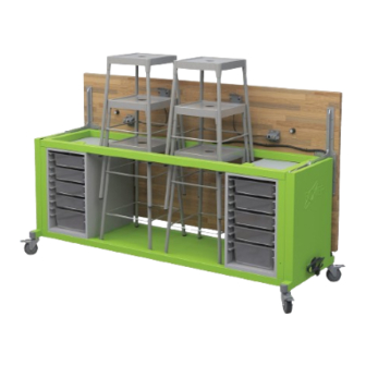
- Page 26 CompletedRoverTable...
Need help?
Do you have a question about the ROVER MAKERSPACE and is the answer not in the manual?
Questions and answers