Table of Contents
Advertisement
Quick Links
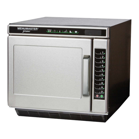
Commercial Microwave—Technical Information
230V, 50 Hz Models
JET514
Due to possibility of personal injury or property damage, always contact an authorized technician for servicing or
repair of this unit.
Refer to Service/Training Manual for installation, operating, testing, troubleshooting, and disassembly instruction.
All safety information must be followed as provided in Service/Training Manual.
To avoid the risk of electrical shock, personal injury or death; disconnect power to oven and discharge capacitor
before servicing, unless testing requires power.
Power Source
Voltage AC
Amperage (Single Unit)
Frequency
Single Phase, 3 wire grounded
Plug
Power Output Microwave
Nominal microwave energy (IEC705)
Minimum temperature rise
Power Consumption
Microwave only
Convection only
Both
Dimensions
Cabinet (in / cm)
Width
Height
Depth
Oven Interior (in / cm)
Width
Height
Depth
Weight
Crated
Uncrated
October 2014
©2014 ACP, Inc.
P2002707M
!
W ARNING
Models
JET514V
Schuko CEE7/7
19 1/4" 489 mm
18 1/8" 460 mm
26 5/8 " 676 mm
13"
10 1/2" 267 mm
15"
112 lbs. 51 kg.
107 lbs. 49 kg.
1
P2002708M
JET514*
230 VAC
16 A
50 Hz
YES
1400 Watts
14ºF / 7.5ºC
500 Watts
2700 Watts
2900 Watts
330 mm
381 mm
16500055
Advertisement
Table of Contents

Related Manuals for ACP JET514


Summary of Contents for ACP JET514
- Page 1 26 5/8 " 676 mm Oven Interior (in / cm) Width 13" 330 mm Height 10 1/2" 267 mm Depth 15" 381 mm Weight Crated 112 lbs. 51 kg. Uncrated 107 lbs. 49 kg. October 2014 16500055 ©2014 ACP, Inc.
-
Page 2: Component Testing Procedures
Triac 3 (rear) is for Microwave voltage, check H.V. board and wiring. MT1 to MT2……………………………… 0VAC Capacitance Meter: ALWAYS DISCHARGE CAPACITOR ! JET514 = .82µ Remove wires from capacitor terminals and Ohm Meter Between Terminals: Capacitor connect ohmmeter on highest resistance Meter should momentarily deflect scale or capacitance meter to terminals. - Page 3 Relay Board With door closed measure resistance from: Pin 1 to pin 4 on J2 connector……………… (Monitor) With door open measure resistance from: Continuity - 0Ω Pin 1 to pin 4 on J2 connector…....October 2014 16500055 ©2014 ACP, Inc.
- Page 4 Side Touch Panel proper operation. and test again. Each pad should respond. If Top Touch Panel still no response, replace Top Touch Panel. Inspect for any damage Display Board – Connector Locations 16500055 October 2014 ©2014 ACP, Inc.
- Page 5 Line Voltage Antenna Motor 230v Door Open Volts J2-4 to J3-1 Line Voltage Microwave Service Test Volts J1-2 to J2-3 Line Voltage Preheat On Heater or Service Volts J1-2 to J2-2 Line Voltage Test #1 October 2014 16500055 ©2014 ACP, Inc.
- Page 6 Power Test All ACP microwave oven power outputs are rated using the IEC705 standards. Using the IEC705 test method requires precision measurements and equipment that is not practical to be performed in the field. Using the test shown below will indicate if the oven performance is satisfactory.
-
Page 7: Service Test Mode
While in this mode, pressing START will reset Magnetron Hours and Door Cycles to 0 Temperature Offset. Pressing 0 will change. +40 to -40 degree range Time Entry 208/230/Automatic Voltage Switching Temperature Displays current oven cavity temperature as sensed by RTD October 2014 16500055 ©2014 ACP, Inc. -
Page 8: User Options Menu
• Offset setting must be reduced by 10° C • If offset is shown as 5°, press the "0" pad until -5 is shown in the display (5– 10= –5). 16500055 October 2014 ©2014 ACP, Inc. -
Page 9: Test Modes
Door Interlock -Verify Latch Mechanism Moves Freely On Primary Switch Door. -Verify J1 Connector On Display Board Is Properly Seated. -Test Interlock Switch Assembly and Perform Door Adjustment If Necessary. -Replace Interlock Switch Assembly. October 2014 16500055 ©2014 ACP, Inc. -
Page 10: Wiring Diagram And Schematic
Wiring Diagram and Schematic W ARNING To avoid risk of electrical shock, personal injury or death; disconnect power to oven and discharge capacitor before servicing, unless testing requires power. 16500055 October 2014 ©2014 ACP, Inc. - Page 11 Wiring Diagram and Schematic W ARNING To avoid risk of electrical shock, personal injury or death; disconnect power to oven and discharge capacitor before servicing, unless testing requires power. October 2014 16500055 ©2014 ACP, Inc.
Need help?
Do you have a question about the JET514 and is the answer not in the manual?
Questions and answers