Table of Contents

Related Manuals for ACP AOC5241


Summary of Contents for ACP AOC5241
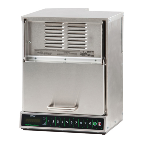
- Page 1 Service Manual Commercial Microwave Oven Style of oven handle may vary MOC5200 AOC5241 MOC6200 MOC5241 OC24BKSA OC5241BK MOC5241I OC5241T1BK MOC5201 OC5241HJ MOC5201J MOC5201U 50 Hz 16400008 February 2016 Rev.2 February 2016...
-
Page 2: Table Of Contents
TABLE OF CONTENTS IMPORTANT INFORMATION ....................1 IMPORTANT SAFETY INFORMATION .................. 2-5 Oven Specifications ......................6 Oven Construction ......................7-11 Oven Performance Test ........................12 Component Test Procedures ..................13-16 Troubleshooting Chart ....................17-18 Wiring Diagram ........................19 Schematic Diagram ......................20 - ii -... -
Page 3: Important Information
Important Notices for Servicers and Consumers ACP will not be responsible for personal injury or property damage from improper service procedures. Pride and workmanship go into every product to provide our customers with quality products. It is possible, however, that during its lifetime a product may require service. -
Page 4: Important Safety Information
Do not operate on a two-wire extension cord. at any time; nor will it be condoned by ACP. IMPORTANT: Before returning a unit to a Before servicing the unit (if unit is operable) perform customer, be sure to check for proper switch the microwave leakage test. -
Page 5: Important Safety Instructions
IMPORTANT SAFETY INSTRUCTIONS Recognize this symbol as a SAFETY message WARNING When using electrical equipment, basic safety precautions should be followed to reduce the risk of burns, electrical shock, fire, or injury to persons including the following. 1. READ all instructions before using equipment. 9. - Page 6 IMPORTANT SAFETY INSTRUCTIONS WARNING WARNING To avoid risk of fire in the oven cavity: Liquids such as water, coffee, or tea are able to be overheated beyond the boiling point without a. DO NOT overcook food. Carefully attend oven appearing to be boiling due to surface tension of the when paper, plastic, or other combustible liquid.
- Page 7 Important Safety Information Grounding Instructions WARNING WARNING To avoid risk of electrical shock, injury or death; make PRECAUTIONS TO BE sure these grounding instructions are followed. OBSERVED BEFORE AND WARNING DURING SERVICING TO Do not remove grounding prong when installing grounded appliance in a home or business that does AVOID POSSIBLE EXPOSURE not have three wire grounding receptacle, under no...
-
Page 8: Oven Specifications
SPECIFICATIONS Model AOC5241 / MOC5241 / OC5241 / MOC5201 / MOC5201J Configuration Countertop or shelf Control System Touch, angled for easy viewing Programmable Control Pads Total Programmable Settings Max. Cooking Time 10:00 Power Levels Defrost Time Entry Option Microwave Distribution... -
Page 9: Oven Construction
OVEN CONSTRUCTION- Left Outer Panel Top Outer Panel Right Outer Panel Door Left Outer Top Outer Panel Panel Right Outer Panel Door... - Page 10 OVEN CONSTRUCTION- Touch Panel Assembly Escutcheon Control Display Board Retainer Clip Retainer Clip Display Board Touch Panel Assembly Escutcheon Control Main Control Board 2.5 Amp Fuse Fan Motor Fan Guard 40 pin Header Bracket 2.5 Amp Fuse Main Control Board 40 Pin Header Bracket Fan Guard...
- Page 11 OVEN CONSTRUCTION- Antenna Antenna Motor Interlock Switch Solenoid Assy Antenna (Top) Interlock Switch (Right Side) Solenoid Assembly Antenna Motor (Right Side) (Bottom) Diode Capacitor Magnetron Magnetron Gasket Magnetron TCO Diodes Latch TCO Capacitors PC Board Harness Magnetrons Latch TCO Magnetron Gaskets Magnetron PC Board...
- Page 12 OVEN CONSTRUCTION- Antenna (Bottom) Grease Shield Ceramic Tray Tray Support Glide Strip 20 Amp Fuse HV Transformer Triac 40A Control Transformer Line Filter 20 Amp Fuse Triac 40A Control HV Transformer Line Filter Transformer Grease Shield Ceramic Tray Glide Strip Tray Support Antenna (Bottom)
-
Page 13: Oven Construction
OVEN CONSTRUCTION- Lower Back Panel Cavity Exhaust Gasket Cavity Exhaust Fan Motor Cavity TCO Cavity Exhaust Motor Gasket Cavity Fan Hood Lower Back Panel Cavity Exhaust Fan Motor Cavity Fan Hood Cavity TCO Hinge Assembly Hinge Assembly Hinge Spring Hinge Spring... -
Page 14: Oven Performance Test
OVEN PERFORMANCE TEST All Amana and Menumaster microwave oven power outputs are rated using the IEC705 standards. Using the IEC705 test method requires precision measurements and equipment that is not practical to be performed in the field. Using the test shown below will indicate if the oven performance is satisfactory. Test equipment required: ... -
Page 15: Component Testing Procedures
COMPONENT TESTING PROCEDURES WARNING To avoid risk of electrical shock, personal injury or death; disconnect power to oven and discharge capacitor before servicing, unless testing requires power. Illustration Component Testing Results Magnetron TCO Disconnect all wires from TCO. Measure resistance across terminals. Magnetron TCO........ - Page 16 COMPONENT TESTING PROCEDURES WARNING To avoid risk of electrical shock, personal injury or death; disconnect power to oven and discharge capacitor before servicing, unless testing requires power. Illustration Component Testing Results Transformer, HV Discharge Capacitor Remove all wires from terminals. Measure resistance from: ...
- Page 17 COMPONENT TESTING PROCEDURES WARNING To avoid risk of electrical shock, personal injury or death; disconnect power to oven and discharge capacitor before servicing, unless testing requires power. Main. Board Function Test Set-Up Meter Probe Placement Results Setting Input to main board Main Board Volts Main Board T-1...
- Page 18 COMPONENT TESTING PROCEDURES WARNING To avoid risk of electrical shock, personal injury or death; disconnect power to oven and discharge capacitor before servicing, unless testing requires power. Function Test Set-Up Meter Setting Probe Placement Results 2.5 amp fuse Remove fuse from Ohms Measure resistance Continuity...
-
Page 19: Troubleshooting Chart
TROUBLESHOOTING CHART Intial Power-Up (Door Open) Connect Power Cord Open Door 1. No power applied to power cord. 2. Oven fuse open. 3. Main board control fuse. 4. Inoperative magnetron TCO. 5. Inoperative cavity TCO. 6. Broken or loose wire. 7. - Page 20 TROUBLESHOOTING CHART Cook Condition Place cup of water in oven and close door 1. Door not closed. 2. Inoperative switch assembly. 3. Broken or loose wire connection. 1. Bad fan. Fans Run 2. Broken or loose wire connection. Press Pad 1 1.
-
Page 22: Schematic Diagram
Schematic Diagram - AOC5241 / OC5241BK / MOC5241 / MOC5201*... - Page 23 50 Hz Commercial Microwave 16400008 July 2012...
Need help?
Do you have a question about the AOC5241 and is the answer not in the manual?
Questions and answers