Table of Contents
Advertisement
Service
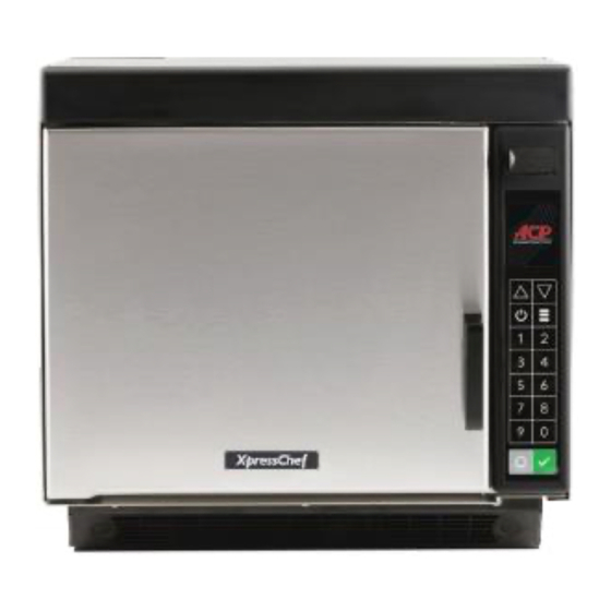
Commercial High Speed Combination Oven
XpressChef Models
Service Manual
This manual is to be used by qualified
service technicians only. ACP, Inc.
does not assume any responsibility for
property damage or personal injury for
improper service procedures done by
an unqualified person.
1
16400046
Revision 1
January 2020
Advertisement
Table of Contents

Related Manuals for ACP XpressChef Series


Summary of Contents for ACP XpressChef Series
- Page 1 Commercial High Speed Combination Oven XpressChef Models Service Manual This manual is to be used by qualified service technicians only. ACP, Inc. does not assume any responsibility for property damage or personal injury for improper service procedures done by an unqualified person.
-
Page 2: Table Of Contents
TABLE OF CONTENTS Important Safety Instructions ..................... 3-4 Oven Specifications 60hz Ovens ..................5 Oven Specifications 60hz Korean Ovens ................6 Oven Specifications 60hz 3 Phase Taiwan Oven ..............7 Oven Specifications 50hz Single Phase Ovens ..............8 Oven Specifications 50hz 3 Phase Ovens ................9 Installation ......................... -
Page 3: Important Safety Instructions
–Outside the U.S.A. and Canada, call 319-368-8120. –Email: Commercialservice@acpsolutions.com. Warranty service must be performed by an authorized ACP servicer. ACP also recommends contacting an authorized ACP servicer, or ACP ComServ Service Support if service is required after warranty expires. PRECAUTIONS TO AVOID POSSIBLE EXPOSURE TO... - Page 4 To avoid risk of personal injury or property damage, observe the following safety CAUTION instructions: General Use: 1. Do not use regular cooking thermometers in oven. Most cooking thermometers contain mercury and may cause an electrical arc, malfunction, or damage to oven. 2.
-
Page 5: Oven Specifications 60Hz Ovens
OVEN SPECIFICATIONS - 60hz CAUTION All safety information must be followed To avoid risk of electrical shock, personal injury, or death, disconnect power to oven and discharge capacitor before servicing, unless testing requires power. Models JET10 (V) JET14 (V)* JET14B or P JET19 (V) JET14VSA JET19VSA... -
Page 6: Oven Specifications 60Hz Korean Ovens
OVEN SPECIFICATIONS - 60hz Korean Models All safety information must be followed W ARNING To avoid risk of electrical shock, personal injury, or death, disconnect power to oven and discharge capacitor before servicing, unless testing requires power. Models JET14K JET14VK Power Source Voltage AC Amperage (single unit) -
Page 7: Oven Specifications 60Hz 3 Phase Taiwan Oven
OVEN SPECIFICATIONS - 60hz 3 Phase - Taiwan All safety information must be followed W ARNING To avoid risk of electrical shock, personal injury, or death, disconnect power to oven and discharge capacitor before servicing, unless testing requires power. Models JET14VT Power Source Voltage AC... -
Page 8: Oven Specifications 50Hz Single Phase Ovens
OVEN SPECIFICATIONS – 50hz Single Phase All safety information must be followed To avoid risk of electrical shock, personal injury, or death, disconnect power to oven and discharge capacitor before servicing, unless testing requires power. Models JET510 (V) JET514 (V)* JET514A JET514C (V) JET514I... -
Page 9: Oven Specifications 50Hz 3 Phase Ovens
OVEN SPECIFICATIONS – 50hz 3 Phase All safety information must be followed W ARNING To avoid risk of electrical shock, personal injury, or death, disconnect power to oven and discharge capacitor before servicing, unless testing requires power. Models JET5193 JET519V3 Power Source Voltage AC Amperage (single unit) -
Page 10: Installation
INSTALLATION IMPORTANT ACP, Inc. Requires Installing a Type D Circuit Breaker for all High-Speed Xpress Oven Installations. Unpacking Oven Inspect oven for damage such as dents in door or dents inside oven cavity. Report any dents or breakage to source of purchase immediately. Do not attempt to use oven if damaged. -
Page 11: Quick Start Reference Guide
QUICK START REFERENCE... -
Page 13: Oven Construction
OVEN CONSTRUCTION BLOWER MOTOR, TOUCH PANEL/DISPLAY, TRANSFORMER Touch Panel/Display Transformer Blower Assembly... - Page 14 OVEN CONSTRUCTION DOOR and DOOR HANDLE Hinge Kit Insulation Inner Door and Latch Assembly Door Handle...
- Page 15 OVEN CONSTRUCTION HV BOARD, MONITOR RELAY BOARD, and CAPACITORS HV Board Monitor Relay Board Triac Cook/Power Relay Diode and Capacitor...
- Page 16 OVEN CONSTRUCTION INTERLOCK, CONVECTION MOTOR, and HEATER BOX Interlock Switch Assembly Convection Motor Assembly Oven Thermal Cutout Convection Motor Heater Catalyst Assembly (if equipped)
- Page 17 OVEN CONSTRUCTION LOWER ACCESS PANEL and Fuse Note: 3 Phase Model Shown Fuse(s) Line Filter Power Cord (not shown)
- Page 18 OVEN CONSTRUCTION MAGNETRONS, STIRRER SYSTEM and TEMP SENSORS Antenna Gears Temp Sensor Thermal Cutout Antenna Magnetrons Antenna Cover...
-
Page 19: Component Testing
COMPONENT TESTING Illustration Component Testing Results Disconnect all wires from TCO. Measure resistance across terminals. Open at 104° C (219° F Cavity Thermal Fuse ........Thermal Cutouts Magnetron TCO ..........Open at 138° C (280° F) and Closed at 82° C (180° F). Discharge Capacitors Infinite resistance should be measured in one direction and... - Page 20 Remove all wires from motor. Blower Motor Measure resistance COM to 208 Approx 23Ω Measure resistance COM to 230 Approx 26Ω Measure resistance 208 to 230 Approx 3Ω Remove all wires from motor. Stirrer Motor- 25RPM Approximately 25k Ω Measure coil resistance Discharge Capacitor Remove all wires from terminals, and Transformer...
-
Page 21: Service Mode
SERVICE MODE TO ENTER SERVICE MODE: 1. Press the Menu Pad. Menu Setting Prompt Appears MENU SCROLL 2. Press the Scroll Down Pad 3. Press “2”. “Service Menu” (five choices appear) 4. At the Pin Prompt, Enter 1,3,5,7,then 9. (the first page of two will appear) Software Version is displayed. -
Page 22: Firmware Update
UPDATING FIRMWARE TO ENTER SERVICE MODE: 1. Insert USB with New Firmware into the USB Port Note: The firmware file must be loaded on a USB Flash Drive, saved in the root directory of the drive, and not located in a folder. 2. -
Page 23: Power Output Test
POWER OUTPUT TEST All Amana and Menumaster microwave oven power outputs are rated using the IEC705 standards. Using the IEC705 test method requires precision measurements and equipment that is not practical to be performed in the field. Using the test shown below will indicate if the oven performance is satisfactory. -
Page 24: Wiring And Schematic Diagrams
WIRING AND SCHEMATIC DIAGRAMS JET10 P2007631M JET10V P2007632M... - Page 25 JET10 P2007631M JET10V P2007632M...
- Page 26 JET510 P2007633M JET510V P2007634M...
- Page 27 JET510 P2007633M JET510V P2007634M...
- Page 28 JET14 P2007603M JET14V P2007601M JET19 P2007610M JET19V P2007611M JET19VTG P2007612M JET19P P2007621M...
- Page 29 JET14 P2007603M JET14V P2007601M JET19 P2007610M JET19V P2007611M JET19VTG P2007612M JET19P P2007621M...
- Page 30 JET14VSA P2007625M JET514 P2007604M JET514A P2007627M JET514BL P2007628M JET514C P2007613M JET514I P2007606M JET514U P2007614M JET514V P2007602M JET514VC P2007615M JET5192 P2007616M JET519V2 P2007617M...
- Page 31 JET14VSA P2007625M JET514 P2007604M JET514A P2007627M JET514BL P2007628M JET514C P2007613M JET514I P2007606M JET514U P2007614M JET514V P2007602M JET514VC P2007615M JET5192 P2007616M JET519V2 P2007617M...
- Page 32 JET14K P2007622M JET14VK P2007623M...
- Page 33 JET14K P2007622M JET14VK P2007623M...
- Page 34 JET14VT P2007624M...
- Page 35 JET14VT P2007624M...
- Page 36 JET14VSA P2007626M...
- Page 37 JET14VSA P2007626M...
- Page 38 JET14B P2007620M...
- Page 39 JET14B P2007620M...
- Page 40 JET5193 P2007618M JET519V3 P2007619M...
- Page 41 JET5193 P2007618M JET519V3 P2007619M...
Need help?
Do you have a question about the XpressChef Series and is the answer not in the manual?
Questions and answers
Need service Manuel for mcp22db